Seismic Vulnerability and Parametric Study on a Bare Frame Building in Nepal
 Rakesh Dumaru
 Hugo Rodrigues
 André Furtado
 Humberto Varum
- 1CONSTRUCT-LESE, Civil Engineering Department, Faculty of Engineering of the University of Porto, Porto, Portugal
- 2RISCO, School of Technology and Management, Polytechnic of Leiria, Leiria, Portugal
The influence of the infill masonry walls in the structural response of reinforced concrete (RC) structures when subjected to earthquakes is not considered in Nepal National Building code and Indian Standard code. Field observations carried out after the 25th April Gorkha earthquake in Nepal reinforce the importance of the infill walls, namely, through the significant increasing of the structural stiffness and by the possibility of introducing unexpected mechanisms that can cause extensive damages or even the collapse of the structure. This article focuses on the study of an existing bare frame, representative of the Nepalese RC buildings, which was modeled and calibrated with data results collected from ambient vibration tests. Initially, a parametric study was conducted with the aim of evaluating the influence of parameters, such as concrete strength and elasticity modulus, slab thickness, and columns cross section in the natural frequencies of the building. The influence of the infill masonry walls in the structural response was evaluated through the modeling of three different numerical models with different disposition of the infill panels from the calibrated existing structure. The seismic vulnerability assessment was performed through non-linear static pushover and dynamic analysis. The results will be presented and discussed in terms of base maximum inter-storey drifts and maximum base shear.
Introduction
Nepal lies in a high-risk seismic vulnerable zone due to the continental lithosphere convergence between the Indian plate and the Eurasian plate. Geological reports indicate that the Indian plate compresses at a rate of 4 mm per year. The history shows that at least one major earthquake occurs every 70–80 years (Chaulagain, 2015), which resulted in several losses of lives and devastating damage to monuments, major importance buildings (such as hospitals and schools), and residential buildings, which consequently had an important impact in the Nepalese economy (Dizhur et al., 2016).
The construction of reinforced concrete (RC) structures was started in Nepal about 30–35 years ago, with a particular increase in the last decade. These structures are built and designed to take only the vertical loads, neglecting the horizontal loads such as wind and earthquakes making them not sufficient to carry lateral loads. For ordinary residential buildings with up to three storeys, the design is carried out using National Building Code (NBC)-205 (NBC 201 1994). For other important buildings, the design is according to NBC-105 (NBC 205, 1994) and Indian Standard (IS)-1893 (IS 1893, 2002). But in actual practice, these codes are either not followed by design engineers or not implemented at a construction site. These design codes do not take into account the influence of the infill masonry walls in the structural response of the structure; however, as observed in the site observations carried out after the 25th April Gorkha earthquake (2015), the infill panels have an important contribution by increasing the structural stiffness and strength, which has direct impact on the structural response. The infills can also introduce different failure mechanisms that could affect the global structure, such as soft-storey mechanism (Figure 1A) and short-column mechanisms (Figure 1B), or can reach local failure mechanism that affect only the panel such as diagonal cracking (Figure 1C) that increase substantially the rehabilitation of the buildings costs (Varum et al., 2016).
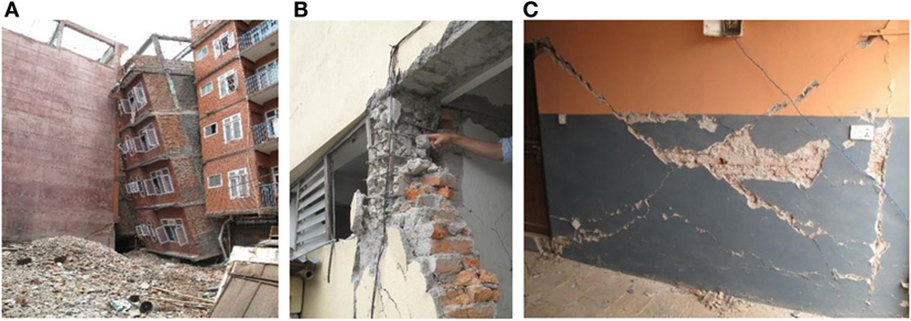
Figure 1. Infill masonry walls failures after the 25th April Gorkha earthquake: (A) soft-storey failure, (B) short-column mechanism, and (C) diagonal cracking.
A significant number of studies showed that the confined masonry walls can exhibit adequate shear and flexural strength with reasonable levels of displacement capacity (Meli, 1973; Alcocer and Meli, 1995; Aguilar et al., 1996; Yoshimura et al., 1996; Tomazevic and Klemenc, 1997). Matsumura (1988) and Gavilan et al. (2015) have demonstrated that a substantial increase in normalized shear strength was observed with decreasing of the panel aspect ratio (H/L). Dawe and Seah (1989), Flanagan et al. (1992), and Mander et al. (1993) have studied the infilled RC frames under in-plane and out-of-plane loads and concluded that this behavior is more complex than the steel infilled frames that have been studied by Fiorato et al. (1970), Klingner and Bertero (1976), and Kahn and Hanson (1979).
Mehrabi et al. (1996) performed the experimental evaluation of masonry-infilled RC frames by using two types of infills, i.e., weak and strong infill, namely 12 ½ scale, single-storey, single-bay, and frame specimens were tested. The results indicate that the infill panels can significantly improve the performance of RC frames. Specimens with strong frame and strong panels exhibit a better performance than those with weak frames and weak panel in terms of load resistance and energy dissipation capacity. Similarly, the lateral loads developed by the infilled frames specimens were always higher than the ones developed by the bare frames (BFs). The results also indicate that the infill panels can be potentially used to improve the performance of existing non-ductile frames.
Pujol et al. (2008) carried out a full-scale test on a three-storey RC structure. The structure was strengthened with infill brick walls, and the results showed that the addition of the infill walls help to prevent the slab collapse and increased the strength (by 100%) and stiffness (by 500%) of the original RC structure. Dolsek and Fajfar (2008) use deterministic assessment on the effect of masonry infills on the seismic response of a four-storey RC frame. The results demonstrated that the masonry infill walls highly increase the structural stiffness and strength as long as the seismic demand does not exceed the deformation capacity of the infills. The infills can completely change the distribution of damage throughout the structure. It was also concluded by the author that the infills can have a beneficial effect on the structural response, if adequately distributed in plant and height, preventing the shear failure of the columns. Varum (2003) carried out the experiments on infills and emphasized on the need of considering the infills for the assessment and redesign of existing structures. The results show that the masonry infill panels increase the natural frequencies of the structure about four times compared to the BFs. The test on the infilled frame confirmed that infill panels protect the RC frame structure from low- to medium-intensity earthquake.
Koutromanos et al. (2012) performed a shaking table test of a three-storey infilled RC frame, and the results show that infilled RC frames can behave in a safe manner during strong earthquakes. These tests have also shown that walls with openings are much more vulnerable to out-of-plane collapse than solid walls. Structures could retain 84% of the peak strength at a drift of 1.03%. Preti et al. (2015) performed experimental testing of engineered masonry infill walls subjected to both in-plane and out-of-plane loadings. The infills were designed with horizontal sliding joints that make the infill capable of absorbing 2.5% in-plane drift with negligible damage, a stable hysteretic response, and no strength degradation. Furtado et al. (2016) tested three full-scale infilled RC frames subjected to static out-of-plane loadings with and without previous damage and observed that the out-of-plane capacity of an infill panel with previous in-plane damage reduced up to 30% of the original capacity.
Chaulagain (2015) carried out a numerical study with the aim of evaluating the influence of infill walls made by solid bricks in the structural response of RC structures. The authors concluded that the presence of the infills increased the structural stiffness in engineered, non-engineered, and well-designed structures about (4–12), 20, and (2–7.5) times than BF structure, respectively. Similarly, the structural strength capacity increased in engineered, non-engineered, and well-designed structures in the range of (3–4.5), (6.3–7.7), and (2.4–2.5) times, respectively.
Bolis et al. (2016) investigated numerically the in-plane performance of masonry-infilled RC frames with sliding joints (Stafford Smith, 1966; Stafford Smith and Carter, 1969; Saneinejad and Hobbs, 1995; Shing and Mehrabi, 2002; Shing and Stavridis, 2014). The proposed solution allows the system to maintain its strength at high deformations (exceeding drifts of 3%) without substantial damage in the masonry. The introduction of gap and sliding joints can reduce the strength if introduced alone in the infill. The major finding of this study is that the length of infill, the friction coefficient along the sliding joints, and the strength of the lateral boards do not affect the global behavior drastically. Furthermore, research studies were carried out with the main goal of evaluating the influence of the infill masonry walls in the structural response of RC frames (Mainstone, 1974; Doudoumis and Mitsopoulou, 1986; Stavridis and Shing, 1997; El-Dakhakhni et al., 2003; Crisafulli and Carr, 2007; Kadysiewski and Mosalam, 2009; Koutromanos et al., 2011; Cavaleri and Di Trapani, 2014, 2015; Campione et al., 2015; Asteris et al., 2016; Furtado et al., 2016).
In this article, an existing BF structure in Nepal was studied to evaluate the influence of the infill masonry walls in the structural response under earthquakes. For this, a 3D numerical model was generated using the software SeismoStruct (Seismosoft, 2006) and was calibrated with data results from ambient vibration tests described and presented in this article. A parametric study was carried out with the aim of evaluating the influence of some mechanical variables in the frequencies of the structure. Non-linear static pushover and dynamic analysis were conducted to assess the seismic vulnerability of the structure considering disposition of infill panels and thus evaluate their influence in the structural response.
Case Study
General Description
An existing BF building, illustrated in Figure 2, located at south east of Bhaktapur about 600 m far away from Jagati and representative of a general construction practice of the area was selected for this study. It is a three-storey building with constant storey height of 2.74 m. The building has two bays in N–S direction (X-direction) and three bays in E–W direction (Y-direction) (Figures 2B,C). The maximum span between columns is 3.5 m and 4.7 m in N–S and E–W direction, respectively. The rectangular column cross sections are 300 mm × 230 mm and 230 mm × 230 mm, and the circular column cross section has the diameter of D = 230 mm. The longitudinal reinforcement of the column is 6ø12 mm with the transversal reinforcement of ø6 mm//150 mm. The beam section is 230 mm × 355 mm excluding slab thickness. The slab thickness is 125 mm and constant throughout. Similarly, the beams’ longitudinal reinforcement is composed by 3ø12 mm on top and on bottom. Cross sections of all the elements are illustrated in Figure 2D.
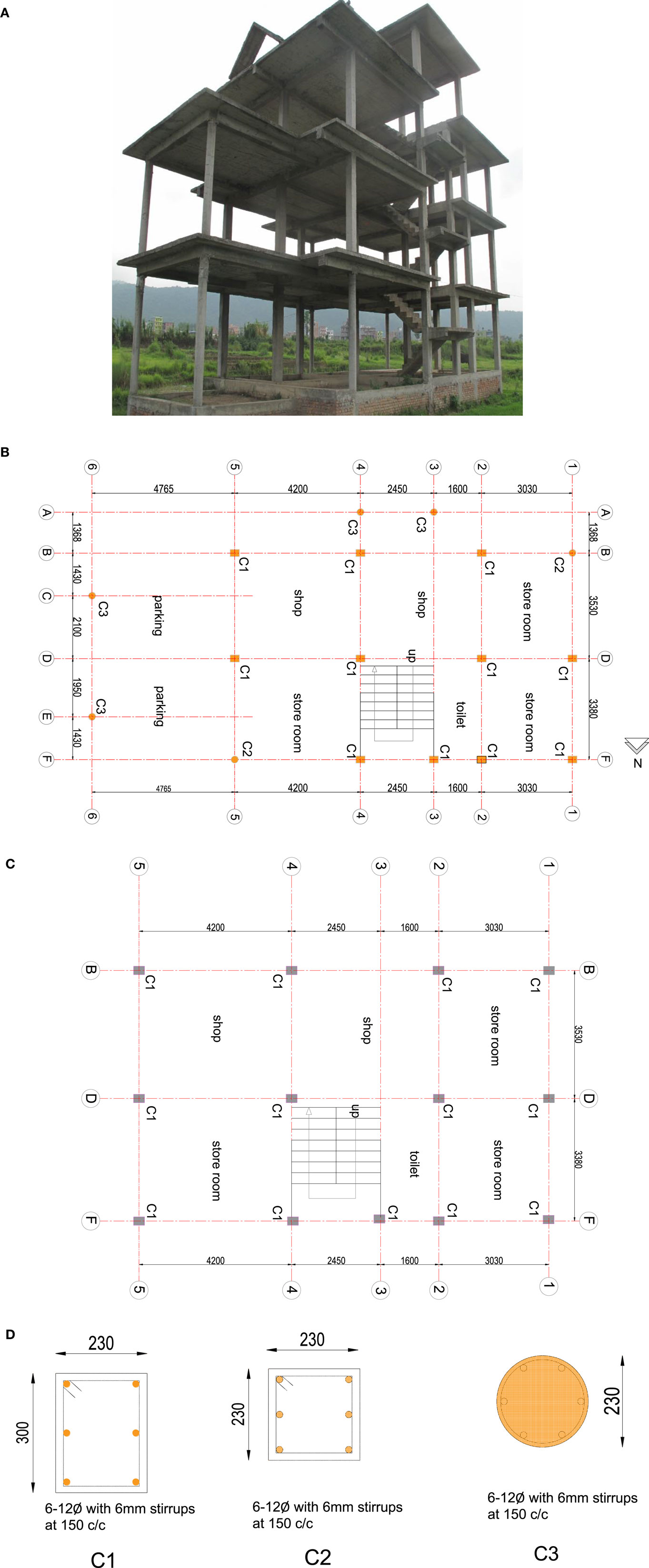
Figure 2. Case study: (A) a three-dimensional view; (B) ground floor, first floor, and second floor plan; (C) top floor plan; and (D) columns section detailing (all dimension in millimeters).
An in situ visual inspection allows to detect the structural defects such as short column at stair case landing, discontinuity of beam at floor level, lack of column at beam to beam connection, and change of circular column at ground floor to rectangular at subsequent floors. Similarly, exposure of reinforcement, insufficient effective cover, poor material quality, and poor workmanship results in the vulnerability of the structure. These problems motivated the selection of this building for this study.
In Situ Experimental Tests
Schmidt Hammer Test
Schmidt hammer tests were realized in different columns, beams, and slabs to measure their expedited concrete compressive strength. The rebound number indicates whether the concrete is soft or hard, which depends on the factors such as smooth or flat surface, concrete age, surface and internal moisture, shape and size of coarse aggregate, and type of cement. For each test, 16 data records were collected for each beam, column, and slab and then averaged. From the results summarized in Table 1, it can be observed that beams and columns obtained results around 20 and 25 MPa, respectively. The slabs tests results were slightly lower, around 15 MPa.
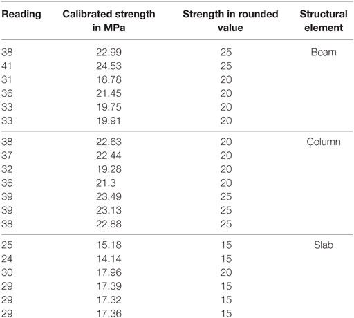
Table 1. Case study: Schmidt hammer test results.
Ambient Vibration Tests
Ambient vibration tests were performed to acquire the natural frequencies and vibration modes of the structure using three-directional accelerometers. The acquisition time was 15 min with a sampling frequency of 2048 Hz. Three different test setups were adopted to reach the objective. A reference accelerometer was placed at the center of the top floor, and different dispositions of the other two accelerometers were adopted for the three setups as shown in Figure 3.
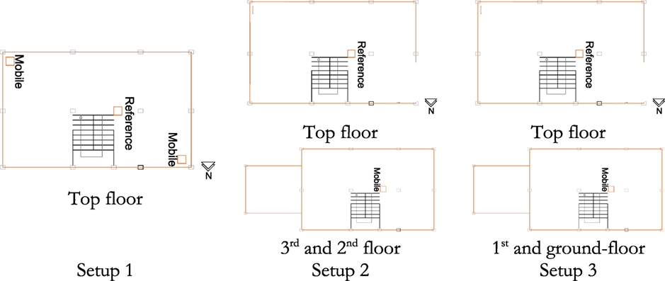
Figure 3. Ambient vibration tests setup schematic layout.
The modal identification was performed through the application of the Enhanced Frequency Domain Composition method in ARTeMIS (2009). Figure 4A illustrates the singular and normalized curves from the spectral matrix for all the accelerations measured, which the fundamental frequencies determined for the building was f1 = 1.404 Hz and f2 = 1.575 Hz and the corresponding vibration modes are shown in Figures 4B,C.
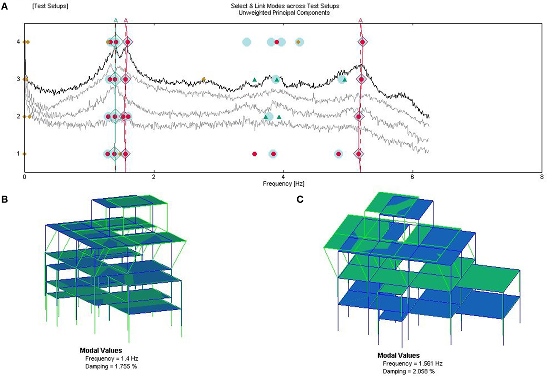
Figure 4. Ambient vibration tests results: (A) spectral density of frequencies; (B) first natural frequency and mode shape, (C) second natural frequency and mode shape.
Numerical Modeling
The building was modeled using SeismoStruct (Seismosoft, 2006) software, which is based on finite element analysis and is capable of predicting large displacement behavior of space frame under static or dynamic loading considering material inelasticity and geometrical non-linearities. This fiber-based approach represents the cross section behavior where each fiber is associated with uniaxial stress–strain relationship (Rodrigues et al., 2012).
The beams and columns were modeled as inelastic force-based frame element type. These elements were discretized in to 5 integration sections and 150 section fibers. Concrete uniaxial material model adopted is based on the constitutive relationship proposed by Mander et al. (1988) and cyclic rule proposed by Martinez-Rueda and Elnashai (1997), initially programed by Madas and Elnashai (1992) that is based on uniaxial non-linear constant confinement model. Lateral transverse reinforcement confinement effect is incorporated by Mander et al. (1993), whereby constant confining pressure is assumed throughout entire stress–strain range. Uniaxial steel model as proposed by Menegotto and Pinto (1973) is coupled with isotropic hardening rules proposed by Filippou and Fenves (2004). Bauschinger effect is taken into account in this model that represents the columns’ stiffness degradation under cyclic loading. The 3D numerical model built for the analysis is shown in Figure 5.
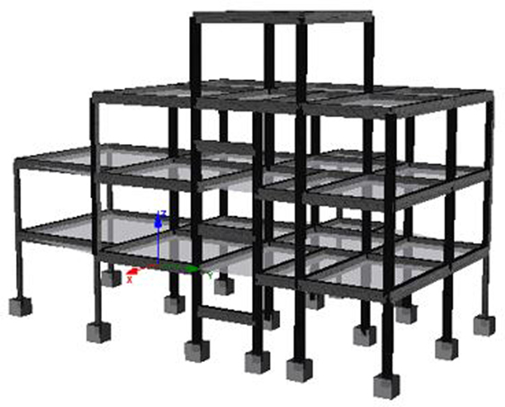
Figure 5. General view of the 3D numerical model.
The material properties adopted for the concrete and steel are presented in Table 2. Table 3 summarizes the existing dead loads adopted for the numerical model. The model was calibrated considering the results from the Schmidt hammer tests.
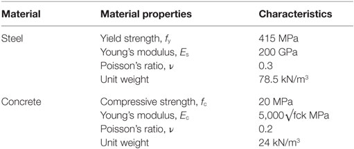
Table 2. Material properties for case study building (NBC 105, 1994; IS 1893, 2002).
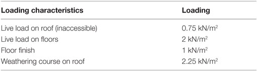
Table 3. Load values adopted for numerical analysis of bare frame structure considering the presence of infill masonry walls (IS 875-1, 1987; IS 875-2, 1987).
Results and Discussions
Parametric Study
A parametric study was performed to calibrate the numerical model by comparing the experimental frequency with the numerical frequency. This is carried out with the variation of parameters such as the concrete compressive strength and elasticity modulus, columns cross-section dimensions (reduction or uniformization as common in Nepal), and slab thickness, which can affect the natural frequencies of the structure. Thus, different numerical models were built based on the calibrated model, and different variations were tested, which are as follows:
• Variation of the concrete elasticity modulus between 11 and 22 GPa: from the comparison with the calibrated model results (exp. f1 and exp. f2) it can be observed that for E = 22 GPa, the frequencies increased around 30% (first and second frequencies), and for the E = 10 GPa, only the first frequency was reduced about 5% as shown in Figure 6.
• Variation of the columns cross section: three different columns cross sections were assigned to understand their influences in the variation of the building cross section as illustrated in Figure 7. For the columns typical cross sections based on the common practices in Nepal, were selected for all the building, namely: 230 mm × 230 mm; 230 mm × 300 mm, and 300 mm × 300 mm. No significant change of the frequencies was observed when all column sizes were assigned as 300 mm × 300 mm; however, the frequencies were reduced about 26% when all column sizes change to 230 mm × 230 mm. Similarly, the buildings frequencies increased by about 23% when all column sizes were 300 mm × 300 mm.
• Variation of the concrete strength: different concrete strengths were tested representative of the concrete Nepalese, namely M10, M15, M16, M17, M18, M19, and M20. From the results (Figure 8), it can be observed that the buildings’ natural frequencies increase with the increase of the concrete strength, namely, can increase around 22% of the first frequency of the building and 18% the second for the concrete strength M20.
• Variation of the slabs thickness: test the influence of slabs thickness (Figure 9) in the buildings’ natural frequencies and it also test the influence of the thicknesses of t = 100 mm, t = 120 mm, t = 125 mm, and t = 130 mm (representative of Nepal). For t = 100 mm, an increase of 33% can be observed for the first frequency and 24% for the second frequency.
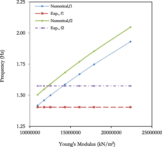
Figure 6. Parametric study results – influence of concrete elasticity modulus variation.
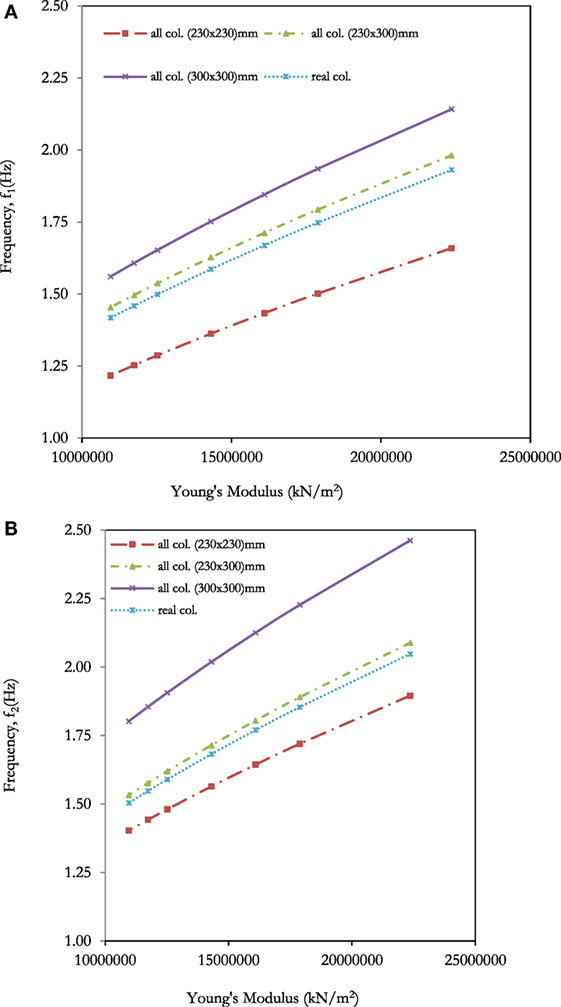
Figure 7. Parametric study results – influence of the building’s columns cross section variation: (A) first frequency; (B) second frequency.
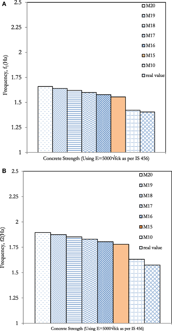
Figure 8. Parametric study results – influence of the building’s concrete strength: (A) first frequency; (B) second frequency.
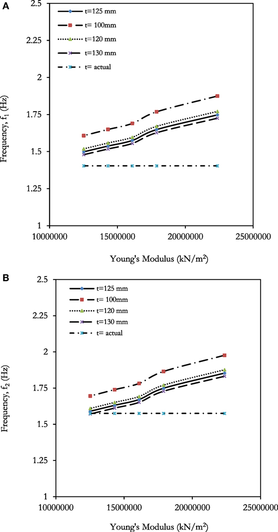
Figure 9. Parametric study results – influence of the building’s slab thickness: (A) first frequency; (B) second frequency.
Non-Linear Static Pushover Analysis
The non-linear static pushover analysis is performed to estimate the horizontal capacity of the structures. This can be performed as either forced based or displacement based depending on the nature of load and expected behavior of the structure. It was carried out as uniform, triangular, and adaptive (based on the response spectrum of the building) pushover analysis to evaluate the original capacity of the building. The capacity curve is plotted in Figure 10, and it can be observed that the BF has maximum shear capacity in X-direction than Y-direction in all load patterns.
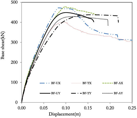
Figure 10. Non-linear static pushover analysis results – bare frame model.
Evaluation of Influence of Infill Masonry Panel on the Structural Response
General Considerations
The infill masonry walls can be modeled through a simplified macro-model (Crisafulli and Carr, 2007; Furtado et al., 2015) or detailed micro-model (Crisafulli and Carr, 2007; Rodrigues et al., 2008; Asteris et al., 2011). In this section, the main goal was to evaluate the influence of the infill masonry walls in the seismic behavior of the structure. Therefore, three different numerical models were built with different arrangement of the infill panels in the structure according to common typologies in Nepal, and the natural frequencies and corresponding vibration modes, capacity curves from the non-linear static adaptive pushover analysis, and the seismic assessment through the realization of non-linear dynamic analysis were evaluated.
Numerical Modeling Approach
The masonry infill walls were modeled through the simplified macro-model proposed by Crisafulli (1997), which consider two pairs of compression-tension diagonal struts and two pairs of shear struts with a shear spring at the middle of the struts as illustrated in Figure 11. The infill panels are modeled by connecting four adjacent nodes and assigned as inelastic infill panel element.
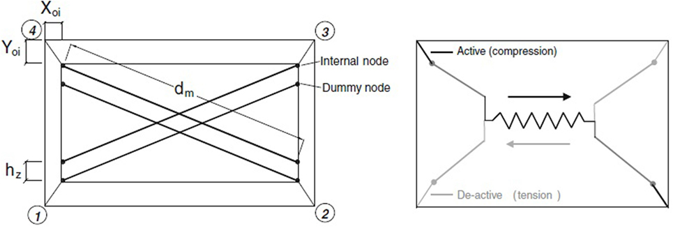
Figure 11. Infill masonry walls numerical model approach proposed by Crisafulli (1997).
Regarding the infill panel’s characteristics, it was considered solid bricks of size 230 mm × 115 mm × 75 mm and cement mortar of 10 mm thickness. To the peripheral walls was assigned 230 mm thickness and internal as partition of 115 mm thickness. The reduction of area for openings was considered as proposed by Madas and Elnashai (1992). The remaining masonry properties adopted for the numerical modeling are summarized in Table 4.
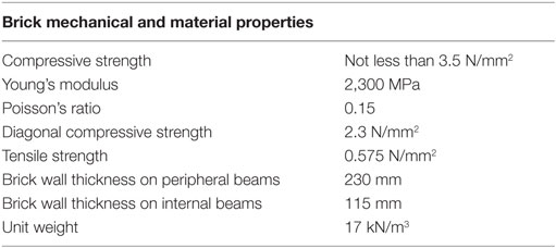
Table 4. Material properties adopted for brick infill panels numerical modeling (NBC 105, 1994).
Three different numerical models were built with different disposition of the infill panels taking into account the most representative of the Nepalese construction practice according to the literature (Chaulagain et al., 2013; Varum et al., 2016). Furthermore, gravity loadings related to residential buildings according to the Nepalese standards were introduced and summarized in Table 3.
To evaluate the influence of considering only the mass contribution of infill walls and not the stiffness during an earthquake, a BF model with the same loads was built similar to the BF with full infill walls but without their stiffness and strength contribution. It was considered as a BF without ground infill (BF-W/O-GI) to represent the typical “soft-storey buildings,” BF without internal infill (BF-W/O-Int), and BF with infill (BF-W-I), which are illustrated in Figure 12.
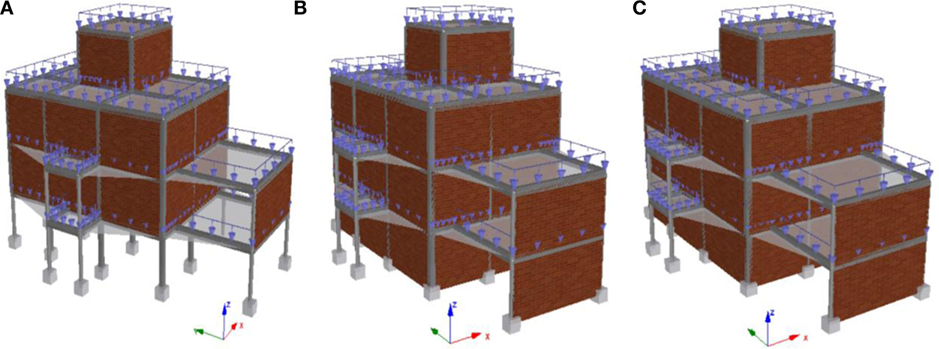
Figure 12. 3D Models considering different disposition of the infill masonry walls: (A) BF-W/O-GI, (B) BF-W/O-Int, and (C) BF-W-I.
Results and Discussion
Different type of analysis was performed on the structure, such as Eigen value analysis and non-linear time history analysis. The capacity of the structure for the different numerical models were compared, and seismic vulnerability was evaluated based on the inter-storey drift (%) and IS drift profile. Various analyses performed and results obtained are discussed below.
Eigen Value Analysis
The natural frequencies of vibration for different assumed conditions were analyzed and compared as shown in Table 5. Higher frequency increases the demand capacity of the structure based on response spectrum. The result shows that the BF-W-I has higher frequency, almost 4 and 3.80 times higher for the first and second experimental frequencies. The numerical model Frame w/o ground infill (BF-W/O-GI) reached only an increase of the natural frequencies of about 1.4 times in both directions.
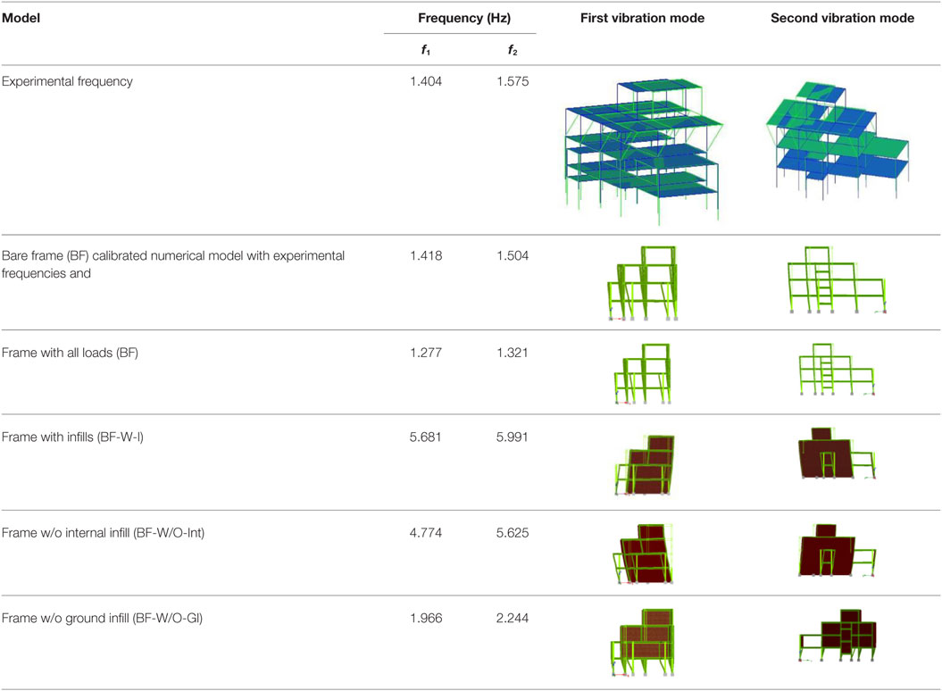
Table 5. Eigen value analysis results: natural frequencies and vibration modes.
Non-Linear Static Pushover Analysis
The capacity curves for the four numerical models considering different assumed conditions are plotted as shown in Figure 13 in X- and Y-direction, respectively. The model with full infill walls disposition, BF-W-I, shows higher strength for same displacement when compared with the other ones. From the results, it is notorious that the presence of infill masonry walls increases the lateral stiffness and strength. The models BF-W/O-GI and BF have approximately same maximum strength; however, BF-W/O-GI has maximum strength at slight prior displacement in both X and Y directions, i.e., yielding in BF-W/O-GI takes earlier. For this particular BF building, the capacity of the infill structure BF-W-I increases almost four to five times than that of BF model.
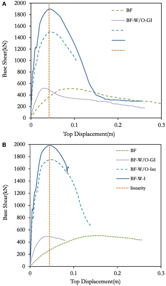
Figure 13. Non-linear static pushover analysis: capacity curves (A) in X-direction and (B) Y direction.
Once the structure undergoes non-linearity, damages in the infill occur, and as a result, the interaction of infill degrades. The capacity of the infilled structures shows higher degradation when compared with that of the BF model. It is observed that the capacity curves of the models BF-W-I and BF-W/O-Int reaches the BF, which means that the infill panels collapsed. At this stage, the infilled is assumed to have completely collapsed and shear cracks in the column appears. Beyond this drifts, the structure can reach the collapse limit state.
Non-Linear Dynamic Analysis
Dynamic analysis predicts the non-linear inelastic behavior of a structure subjected to earthquake loading (for low level of ground excitation, linear elastic dynamic response can be modeled). Twenty real ground motions were selected from the expected response spectra of the structure (Figure 14), the region, and soil of the structure. The records were selected and scaled as proposed by Araújo et al. (2016).
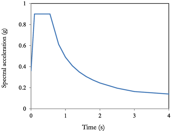
Figure 14. Expected response specter for a site as per Indian Standard 1893 (IS 1893, 2002).
Seismic Vulnerability Assessment
The vulnerability of the structure at different peak ground acceleration (PGA) can be obtained by plotting maximum inter-storey drift Vs PGA (g). The maximum inter-storey drift observed for all the non-linear dynamic analysis were plotted for the BF, BF-W/O-GI, and BF-W-I as shown in Figure 15. The plot is compared with various limit state proposed to assess the seismic vulnerability of structures, such as VISION2000:1995 (VISION2000, 2000), FEMA-356 (FEMA356, 2000), and Ghobarah (2004) and Ghobarah (2004) proposed limit state for frame structure with non-ductile infill. Comparing the analysis result with limit state proposed by Ghobarah (2004) will give strong validation of the result. Moreover, VISION 2000 (VISION2000, 2000) and FEMA-356 (FEMA356, 2000) proposed limit state for ductile frame and ductile infills. The detail of the limit states are listed in Tables 6–8.
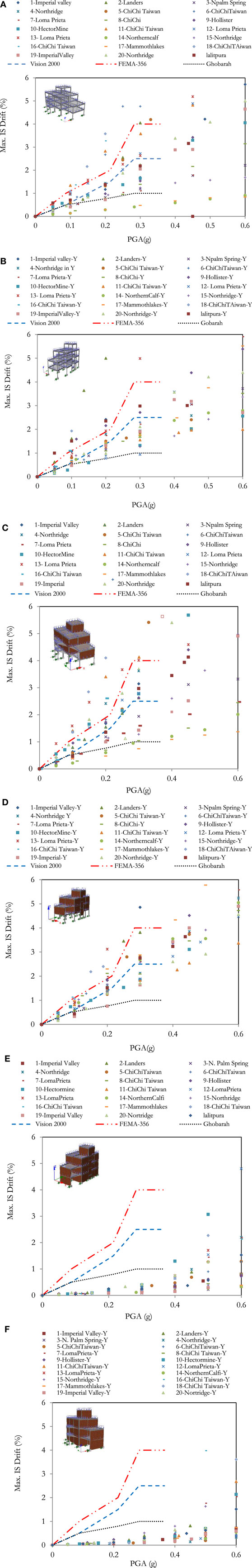
Figure 15. Non-linear dynamic analysis: maximum Indian Standard drift (%) Vs peak ground acceleration (g) for (A,B) BF, (C,D) BF-W/O-GI, and (E,F) BF-W-I for X and Y direction.

Table 6. Storey drift ratio (%) limit proposed by Ghobarah (2004).
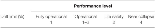
Table 7. Storey drift according to the VISION 2000 (VISION2000, 2000).
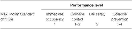
Table 8. Storey drift limit state based on FEMA-356 (FEMA356, 2000).
The plot shows that BF structure remains in moderate damage state for most of the earthquake ground motion at 0.1 g when compared with limit state in X direction proposed by Ghobarah (2004). Up to 0.15 g, the structure reaches partial collapse state, and beyond 0.2 g, it goes complete collapse in X direction. In Y direction, the structure reaches irreparable damage state at 0.1 g and complete collapse at 0.2 g if compared with limit state proposed by Ghobarah (2004). Similarly, the structure remains in operational level until 0.25 g in both X and Y directions if compared with VISION 2000 (VISION2000, 2000) and FEMA-356 (FEMA356, 2000) performance level. It reaches near collapse beyond 0.3 g.
For BF-W/O-GI, the structure goes partial damage state at 0.1 g and collapse state beyond 0.15 g in X direction based on the study by Ghobarah (2004). Similarly in Y direction, the structure undergoes collapse limit state beyond 0.1 g. Based on VISION (VISION2000, 2000), the structure remains life safety until 0.2 g and undergoes near collapse beyond 0.3 g in both X and Y directions. Based on FEMA-356 (FEMA356, 2000), the structure remains damage control till 0.2 g and life safety till 0.25 g in both directions. Collapse of the structure takes place beyond 0.4 g.
For BF-W-I, the structure behaves in safety limit state until 0.4 g compared with all limit defined limit states. After 0.4 g, the structure behaves vulnerable. This approach can be used for the strengthening of the structure. This behavior can be reinforced by the visual inspection of RC buildings having well-constructed infill panel that performed well in 2015 Gorkha earthquake.
Conclusion
Recent earthquakes have demonstrated the significant influence of the infill masonry walls in the seismic response of RC buildings. In Nepal, this type of buildings increased abruptly during the last decade, which is associated with the absence of seismic design, and the consideration of the infills for the structural response of buildings when subjected to lateral loadings resulted in the collapse of several structures during the 25th April Ghorka earthquake. This work presented a numerical study of a real BF RC building existent in Nepal.
Schmidt hammer test was performed at a site to find roughly the characteristic strength of concrete used in this building. Similarly, ambient vibration test was performed using accelerometers at different positions to obtain the fundamental frequency and mode of vibration of the structure and calibrate the numerical model built in the software SeismoStruct (Seismosoft, 2006).
A parametric study was performed to evaluate the influence of certain variables such as concrete elasticity modulus, compressive strength, and columns cross section and slabs thickness in the natural frequencies of the building. From the results, it was observed that the concrete elasticity modulus can increases about 30% for E = 22 GPa when compared with the calibrated one of 12 GPa. From the grade of concrete, a variation of 33 and 24% was observed for the first and second frequency, respectively, for the concrete strength M20 when compared with experimental obtained from the Schmidt hammer. The frequencies reduced by approximately 27% when column sizes are reduced to 230 mm × 230 mm and increased by 23% if all column sizes change to 300 mm × 300 mm.
In addition, the influence of infill masonry walls in the structural response of the building under study was evaluated. For this, three different numerical models with different disposition of the walls were built. From the Eigen value analysis, it was found that BF-W-I has approximately four times higher frequency than existing BF. It can also be concluded, for the same structure, that the mode of vibration does not remain same but varies. From the non-linear static pushover analysis, it was concluded that the full infill model has four times higher maximum strength than the BF model, and it is reached for lower top displacement values. Even the model without infills on the ground floor reaches almost the same maximum strength as that of BF model; however, the maximum strength is reached for half top displacement.
Dynamic time history was performed to find the vulnerability of the structure. It can be concluded that the BF-W/O-GI is most vulnerable followed by BF. Similarly, BF-W-I shows the better performance for all earthquakes. This type of structure remains as moderate damage state till 0.3 g ground acceleration. Beyond 0.4 g, the structure goes to complete collapse state. From this study, it can be concluded that if the ductility can be increased in the infill, the structure can deform for a longer period without collapse, which can be beneficial for alternative strengthening technique. From the drift profile plot, it can be concluded that BF-W/O-GI has maximum drift at ground floor and insignificant at subsequent storeys. In the same way, BF-W-I has less storey drift at all floors, which signifies the proper distribution of plasticity in the structure.
Author Contributions
RD performed the field assessment and the numerical modeling presented in the paper, and helped in the interpretation of the results. AF performed the experimental field tests and helped in the analysis of the results. HR worked on field assessment, experimental test, and numerical modeling and participated in the discussion of the results. HV supervised all the work, especially in the field assessment and numerical analysis and finally in the discussion of the results.
Conflict of Interest Statement
The authors declare that the research was conducted in the absence of any commercial or financial relationships that could be construed as a potential conflict of interest.
Funding
The authors would like to acknowledge the financial support of SmartLink PhD Grant under Erasmus Mundus Action 2, application number SL15DF0066. They would also like to acknowledge the financial support of “FCT – Fundação para a Ciência e Tecnologia,” Portugal, through the research project P0CI-01-0145-FEDER-016898 – ASPASSI Safety Evaluation and Retrofitting of Infill masonry enclosure Walls for Seismic demands.
References
Aguilar, G., Meli, R., and Vasquez-del-Mercado, A. R. (1996). Influence of Horizontal Reinforcement on the Behavior of Confined Masonry Walls. Acapulco: 11th World Conference Earthquake Engineering.
Alcocer, S., and Meli, R. (1995). Test Program on the Seismic Behaviour of Confined Masonry Walls. Boulder: The Masonry Soc. J.
Araújo, M., Macedo, L., Marques, M., and Castro, J. M. (2016). Code-based record selection methods for seismic performance assessment of buildings. Earthq. Eng. Struct. 45, 129–148. doi: 10.1002/eqe.2620
Asteris, P., Antoniou, S., Sophianopoulos, D., and Chrysostomou, C. (2011). Mathematical macromodeling of infilled frames: state of the art. J. Struct. Eng. 137, 1508–1517. doi:10.1061/(ASCE)ST.1943-541X.0000384
Asteris, P. G., Cavaleri, L., Di Trapani, F., and Sarhosis, V. (2016). A macro-modelling approach for the analysis of infilled frame structures considering the effects of openings and vertical loads. Struct. Infrastruct. Eng. 12. doi:10.1080/15732479.2015.1030761
Bolis, V., Stavridis, A., ASCE, A., and Preti, M. (2016). Numerical investigation of the in-plane performance of masonry-infilled RC frames with sliding subpanels. J. Struct. Eng. 04016168, 1–18. doi:10.1061/(ASCE)ST.1943-541X.0001651
Campione, G., Cavaleri, L., Macaluso, G., Amato, G., and Di Trapani, F. (2015). Evaluation of infilled frames: an updated in-plane-stiffness macro-model considering the effects of vertical load. Bull. Earthq. Eng. 13, 2265–2281. doi:10.1007/s10518-014-9714-x
Cavaleri, L., and Di Trapani, F. (2014). Cyclic response of masonry infilled RC frames: experimental results and simplified modelling. Soil Dyn. Earthq. Eng. 65, 224–242. doi:10.1016/j.soildyn.2014.06.016
Cavaleri, L., and Di Trapani, F. (2015). Prediction of the additional shear action on frame members due to infills. Bull. Earthq. Eng. 13, 1425–1454. doi:10.1007/s10518-014-9668-z
Chaulagain, H. (2015). Seismic Assessment and Retrofitting of Existing Buildings in Nepal. Aveiro: Civil Department, University of Aveiro.
Chaulagain, H., Rodrigues, H., Jara, J., Spacone, E., and Varum, H. (2013). Seismic response of current RC buildings in Nepal: a comparative analysis of different design/construction. Eng. Struct. 49, 284–294. doi:10.1016/j.engstruct.2012.10.036
Crisafulli, F. J. (1997). Seismic Behavior of Reinforced Concrete Structures with Masonry Infills. PhD thesis, Christchurch: University of Canterbury.
Crisafulli, F. J., and Carr, A. J. (2007). Proposed macro-model for the analysis of infilled frame structures. Bull. N. Z. Soc. Earthq. Eng. 40, 69–77.
Dawe, J. L., and Seah, C. K. (1989). Behaviour of masonry infilled steel frames. Can. J. Civ. Eng. 16, 865–876. doi:10.1139/l89-129
Dizhur, D., Dhakal, R. P., Bothra, J., and Ingham, J. M. (2016). Building typologies and failure modes observed in the 2015 Gorkha (Nepal) earthquake. N. Z. Soc. Earthq. Eng. 49, 211–232.
Dolsek, M., and Fajfar, P. (2008). The effect of masonry infills on the seismic response of a four-storey reinforced concrete frame – a deterministic assessment. Eng. Struct. 30, 1991–2001. doi:10.1016/j.engstruct.2008.01.001
Doudoumis, N., and Mitsopoulou, N. (1986). Non-linear Analysis of Multi-Storey Infilled Frames for Unilateral Contact Condition. Lisbon: Proc of 8th European Conference on Earthquake Engineering, 63–70.
El-Dakhakhni, W., Elgaaly, M., and Hamid, A. (2003). Three-strut model for concrete masonry-infilled steel frames. J. Struct. Eng. 129, 177–185. doi:10.1061/(ASCE)0733-9445(2003)129:2(177)
Filippou, F. C., and Fenves, G. L. (2004). Methods of Analysis for Earthquake-Resistant Structures in Earthquake Engineering. Cambridge, UK: Cambridge University Press.
Fiorato, A. E., Sozen, M. A., and Gamble, W. L. (1970). An Investigation of the Interaction of Reinforced Concrete Frames with Masonry Filler Walls. Urbana-Chamaign: University of Illinois.
Flanagan, R. D., Bennett, R. M., and Barclay, G. A. (1992). “Experimental testing of hollow clay tile infilled frames,” in Proc. 6th Can. Masonry Symposium (Canada: Univ. of Saskatchewan).
Furtado, A., Rodrigues, H., Arede, A., and Varum, H. (2015). Simplified macro-model for infill masonry walls considering the out-of-plane behaviour. Earthq. Eng. Struct. Dyn. 45, 507–524. doi:10.1002/eqe.2663
Furtado, A., Rodrigues, H., Arêde, A., and Varum, H. (2016). Experimental evaluation of out-of-plane capacity of masonry infill walls. Eng. Struct. 111, 48–63. doi:10.1016/j.engstruct.2015.12.013
Gavilan, J. J. P., Flores, L. E., and Alcocer, S. M. (2015). An experimental study of confined masonry walls with varying aspect ratio. Earthq. Spectra. 31, 945–968. doi:10.1193/090712EQS284M
Ghobarah, A. (2004). On Drift Limits Associated with Different Damage Levels. Bled: International workshop on performance-based seismic design.
IS 1893. (2002). Indian Standard Criteria for Earthquake Resistant Design Structures (Fifth Revision) IS 1893 (Part 1). New Delhi.
IS 875-1. (1987). Code of Practice for Design Loads (Other Than Earthquake) for Buildings and Structures Part 1: Dead Loads – Unit Weights of Building Material and Stored Materials. New Delhi.
IS 875-2. (1987). Code of Practice for Design Loads (Other Than Earthquake) For Buildings And Structures, Part 2: Imposed Loads. New Delhi.
Kadysiewski, S., and Mosalam, K. M. (2009). Modeling of Unreinforced Masonry Infill Walls Considering In-plane and Out-of-Plane Interaction PEER 2008/102. Berkeley, CA: Pacific Earthquake Engineering Research Center.
Kahn, L. F., and Hanson, R. D. (1979). Infilled walls for earthquake strengthening. J. Struct. Div. 105, 283–296.
Klingner, R. E., and Bertero, V. V. (1976). Infilled Frames in Earthquake Resistant Construction. Berkeley: University of California.
Koutromanos, I., Stavridis, A., and Shing, P. B. (2012). Shake-table tests of a three-story reinforced concrete frame with masonry infill walls. Earthq. Eng. Struct. 41, 1089–1108. doi:10.1002/eqe.1174
Koutromanos, I., Stavridis, A., Shing, P. B., and Willam, K. (2011). Numerical modelling of masonry-infilled RC frames subjected to seismic loads. Comput. Struct. 89, 1026–1037. doi:10.1016/j.compstruc.2011.01.006
Madas, P., and Elnashai, A. (1992). A new passive confinement model for the analysis of concrete structures subjected to cyclic and transient dynamic loading. Earthq. Eng. Struct. 21, 409–431. doi:10.1002/eqe.4290210503
Mainstone, R. J. (1974). Supplementary Note on the Stiffness and Strength of Infilled Frames. UK: Building Research Station.
Mander, J. B., Nair, B., Wojtkowski, K., and Ma, J. (1993). An Experimental Study on the Seismic Performance of Brick Infilled Steel Frames with and without Retrofit. Buffalo, NY: State University of New York.
Mander, J. B., Priestleyand, M., and Parks, R. (1988). Theoretical streess-strain model for confined concrete. J. Struct. Eng. 114, 1804–1826. doi:10.1061/(ASCE)0733-9445(1988)114:8(1804)
Martinez-Rueda, J., and Elnashai, A. (1997). Confined concrete model under cyclic load. Mater. Struct. 30, 139–147. doi:10.1007/BF02486385
Matsumura, A. (1988). Shear Strength of Reinforced Masonry Walls. Tokyo-Kyoto, Japan: Ninth World Conference on Earthquake Engineering.
Mehrabi, A. B., Shing, P. B., and Schuller, M. P. (1996). Experimental evaluation of masonry-infilled RC frames. J. Struct. Eng. 122, 228–237. doi:10.1061/(ASCE)0733-9445(1996)122:3(228)
Meli, R. (1973). Behavior of Masonry Walls under Lateral Loads. Tokyo-Kyoto, Japan: Fifth World Conference on Earthquake Engineering, VI.
Menegotto, M., and Pinto, P. (1973). “Method of analysis for cyclically loaded R.C. plane frames including changes in geometry and non-elastic behaviour of elements under combined normal force and bending,” in Symposium on the Resistance and Ultimate Deformability of Structures Acted on by Well Defined Repeated Loads (Zurich, Switzerland: International Association for Bridge and Structural Engineering), 15–22.
NBC 105. (1994). Mandatory Rules of Thumb for Reinforced Concrete Building without Masonry Infill. Kathmandu, Nepal: NBC 105.
NBC 201. (1994). Mandatory Rules of Thumb Reinforced Concrete Buildings with Masonry Infill. NBC 201.
NBC 205. (1994). Mandatory Rules of Thumb Reinforced Concrete Buildings without Masonry Infill 1994. NBC 205.
Preti, M., Migliorati, L., and Giuriani, E. (2015). Experimental testing of engineered masonry infill walls for post-earthquake structural damage control. Bull. Earthq. Eng. 13, 2029–2049. doi:10.1007/s10518-014-9701-2
Pujol, S., Climent, A. B., Rodriguez, M. E., and Smith-Pardo, J. P. (2008). Masonry Infill Walls: An Effective Alternative for Seismic Strengthening of Low-Rise Reinforced Concrete Building Structures. Beijing, China: The 14th World Conference on Earthquake Engineering.
Rodrigues, H., Varum, H., Arede, A., and Costa, A. (2012). A comparative efficiency analysis of different non-linear modelling strategies to simulate the biaxial response of RC columns. Earthq. Eng. Eng. Vib. 11, 553–566. doi:10.1007/s11803-012-0141-1
Rodrigues, H., Varum, H., and Costa, A. (2008). A non-linear masonry infill macro-model to represent the global behaviour of buildings under cyclic loading. Int. J. Mech. Mater. Des. 4, 123–135. doi:10.1007/s10999-008-9070-6
Saneinejad, A., and Hobbs, B. (1995). Inelastic design of infilled frames. J. Struct. Eng. 121, 634–650. doi:10.1061/(ASCE)0733-9445(1995)121:4(634)
SeismoSoft. (2006). SeismoStruct—A Computer Program for Static and Dynamic Nonlinear Analysis of Framed Structures [Online]. Available at: http://www.seismosoft.com
Shing, P. B., and Mehrabi, A. B. (2002). Behavior and analysis of masonry-infilled frames. Progr. Struct. Eng. Mater. 4, 320–331. doi:10.1002/pse.122
Shing, P. B., and Stavridis, A. (2014). Analysis of Seismic Response of Masonry-Infilled RC Frames through Collapse. ACI Struct. J. 297–307.
Stafford Smith, B., and Carter, C. (1969). “A method for analysis for infilled frames,” in Proceedings of Institution of Civil Engineers, 44, 31–48.
Stavridis, A., and Shing, P. B. (1997). Finite element modelling of masonry-infilled RC frames. J. Struct. Eng. 136, 604–613.
Tomazevic, M., and Klemenc, I. (1997). Behavior of confined masonry walls. Earthq. Eng. Struct. D. 26, 1059–1071. doi:10.1002/(SICI)1096-9845(199710)26:10<1059::AID-EQE694>3.0.CO;2-M
Varum, H. (2003). Seismic Assessment, Strengthening and Repair of Existing Buildings. Aveiro: Universidade de Aveiro, University of Aveiro.
Varum, H., Furtado, A., Rodrigues, H., Oliveira, J., Vila-Pouca, N., and Arêde, A. (2016). Seismic performance of the infill masonry walls and ambient vibration tests after the Ghorka 2015, Nepal earthquake. Bull. Earthquake Eng. doi:10.1007/s10518-016-9999-z
VISION2000. (2000). Performance Based Seismic Engineering of Buildings. Sacramento, CA: Structural Engineers Association of California.
Keywords: Nepal, bare frame RC building, numerical modeling, ambient vibration tests, parametric study, masonry infill walls
Citation: Dumaru R, Rodrigues H, Furtado A and Varum H (2016) Seismic Vulnerability and Parametric Study on a Bare Frame Building in Nepal. Front. Built Environ. 2:31. doi: 10.3389/fbuil.2016.00031
Received: 01 September 2016; Accepted: 06 December 2016;
Published: 23 December 2016
Edited by:
Panagiotis G. Asteris, School of Pedagogical and Technological Education, GreeceReviewed by:
Eleni Smyrou, Istanbul Technical University (ITU), TurkeyMichele Betti, University of Florence, Italy
Fabio Di Trapani, University of Palermo, Italy
Constantinos Repapis, Piraeus University of Applied Sciences, Greece
Copyright: © 2016 Dumaru, Rodrigues, Furtado and Varum. This is an open-access article distributed under the terms of the Creative Commons Attribution License (CC BY). The use, distribution or reproduction in other forums is permitted, provided the original author(s) or licensor are credited and that the original publication in this journal is cited, in accordance with accepted academic practice. No use, distribution or reproduction is permitted which does not comply with these terms.
*Correspondence: Humberto Varum, hvarum@fe.up.pt