Transition wave in the collapse of the San Saba Bridge
 Michele Brun
 Gian Felice Giaccu3
 Alexander B. Movchan
- 1Dipartimento di Ingegneria Meccanica, Chimica e dei Materiali, Università di Cagliari, Cagliari, Italy
- 2Department of Mathematical Sciences, University of Liverpool, Liverpool, UK
- 3Dipartimento di Architettura, Design e Urbanistica, Facoltà di Architettura, Università di Sassari, Alghero, Italy
- 4School of Mechanical Engineering, Tel Aviv University, Tel Aviv, Israel
- 5Department of Mathematics and Physics, Aberystwyth University, Aberystwyth, UK
A domino wave is a well-known illustration of a transition wave, which appears to reach a stable regime of propagation. Nature also provides spectacular cases of gravity-driven transition waves at large scale observed in snow avalanches and landslides. On a different scale, the micro-structure level interaction between different constituents of the macro-system may influence critical regimes leading to instabilities in avalanche-like flow systems. Most transition waves observed in systems, such as bulletproof vests, racing helmets under impact, shock-wave-driven fracture in solids, are transient. For some structured waveguides, a transition wave may stabilize to achieve a steady regime. Here, we show that the failure of a long bridge is also driven by a transition wave that may allow for steady-state regimes. The recent observation of a failure of the San Saba Bridge in Texas provides experimental evidence supporting an elegant theory based on the notion of transition failure wave. No one would think of an analogy between a snow avalanche and a collapsing bridge. Despite an apparent controversy of such a comparison, both these phenomena can be described in the framework of a model of the dynamic gravity driven transition fault.
Introduction
The long San Saba railway bridge (Figure 1C) in the Central Texas (also known as Harmony Ridge Bridge, 31°14′07 ″ North, 98°33′52″ West) collapsed in May 2013 as a result of initial damage caused by fire. A 300-yard bridge fell apart after catching fire in a dramatic collapse captured on video (https://www.youtube.com/watch?v=LLVKb1HxhAY). This dramatic event was the subject of attention worldwide when it was featured on BBC News and other News programs across the globe. The video footage provides the data for measuring the speed of propagation of the failure, and it is apparent that this failure reaches a steady-state regime.
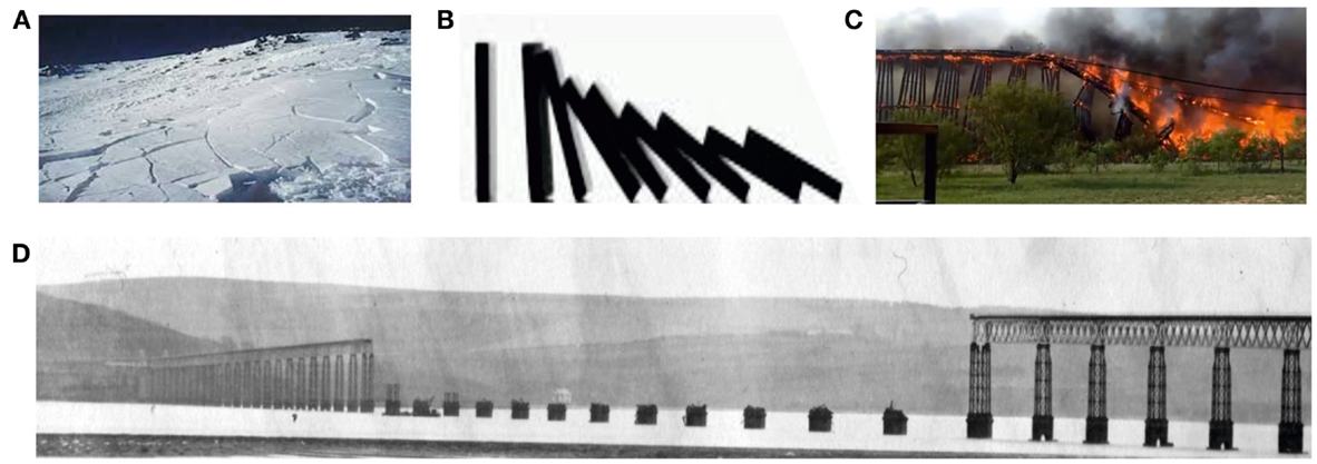
Figure 1. Examples of gravitationally driven failure waves occurring in nature and in structural systems are shown. (A) A slab snow avalanche. (B) A falling domino. (C) The failure of the San Saba Bridge (Texas, May 2013). (D) The Tay Bridge disaster. Dundee, Scotland, 1879 (from http://en.wikipedia.org/wiki/The_Tay_Bridge_Disaster).
Although the phenomenon of collapse of a long bridge is extraordinarily complicated, we show that it can be analyzed in the framework of an analytical model, which refers to gravity driven transition waves. Furthermore, an explicit simple formula has been derived for the speed of the steady-state propagating fault:
where D is the flexural rigidity, ρ is the linear mass density of the bridge, and κ is the stiffness of the supporting pillars.
Several examples of transition faults, included in Figure 1, incorporate an avalanche flow (Figure 1A), gravity-friction-driven domino effect (Figure 1B), the Tay Bridge in Scotland (Figure 1D), and San Saba burning bridge in Texas (Figure 1C). The failures of long bridges were recorded on a number of occasions in the last 200 years. Perhaps, one of the most dramatic events was the Tay Bridge Disaster of 1879, featured in the poetry by McGonnagall, as caused by an impact of a derailed train:
“But when the train came near to Wormit Bay,
Boreas he did loud and angry bray,
And shook the central girders of the Bridge of Tay
On the last Sabbath day of 1879,
Which will be remember’d for a very long time.”
The substantial damage shown in Figure 1D includes multiple sections destroyed, apparently as a result of a failure wave propagating along the bridge. Due to a lack of recording technology, no video footage was available at the time, and no experimental observations were made.
Similar to a slab snow avalanche (Bartelt et al., 2006; Heierli et al., 2008), where the fault (moving snow powder versus solid base) reaches a steady regime, the collapse of the Harmony Ridge Bridge also fits into the framework of transition waves, and moreover, an elegant analytical model enables one to predict the steady regime of propagation of this fault. Although the physical background in these two cases is different, we note that the balance of energy is required, which includes potential, kinetic, and internal energy. The dissipation mechanism in the avalanche flow is explained via heat transfer and friction (Bartelt et al., 2006), whereas in the collapsing bridge the energy is taken away from failure region by radiating waves (Brun et al., 2013a). Also, elegant crack (or anti-crack) propagation models are applicable to both cases (Slepyan, 1981, 2002, 2010; Heierli et al., 2008). A simple gravity-friction-driven failure wave is also known for a domino row (Figure 1B), and the steady-state regime is independent on the initial conditions (Maddox, 1987; Stronge, 1987).
The theoretical background developed by Brun et al. (Brun et al., 2012, 2013b,c) refers to long bridge structures as waveguides rather than finite size elastic bodies. That approach enables one to bring the notion of so-called Floquet–Bloch waves from Physics (Brillouin, 1953; Kittel, 1996) in the areas such as Metamaterials pioneered by Veselago (1968) and Pendry (2000). Important related areas in Applied Mathematics involve averaging and high-frequency homogenization (Movchan and Slepyan, 2007; Craster et al., 2010). Dispersion of waves and the pass band structure are of paramount importance in understanding of fundamental mechanism of vibration of long bridges. For a model example, a recent analytical work (Brun et al., 2013a) presented the analysis of a class of functional equations of the Wiener–Hopf type that describes transition waves in a periodic flexural system. The notion of configurational forces enables us to develop the model further to take into account the non-linear features of the physical problem. The new mathematical approach has delivered an accurate estimate of the failure wave speed in the collapse of the Harmony Ridge Bridge as compared with the rare footage, which was taken during propagation of the fault.
In this paper, we show an unusual, and unexpected to a certain degree, phenomenon of a transition wave in a long collapsing bridge. We also demonstrate the link with a certain class of solutions, known as Bloch waves, in infinite periodic systems, which provide the best description of the influence of individual constituents and their interaction within the macro-system of the bridge. Transition waves and failure phenomena are also considered in relation to damage and impact of structured solids, such as honeycombs and bistable lattices. The approach to failure as a transition wave was advocated through lattice models (Slepyan and Troyankina, 1984; Fineberg and Marder, 1999; Balk et al., 2001; Cherkaev et al., 2005; Slepyan et al., 2005) including the advanced molecular dynamics simulation (Abraham and Gao, 2000).
The importance of such problems is also apparent to elucidate ways to prevent such destructions in earthquake protection systems.
Materials and Methods
Unwanted Vibrations of Long Bridges
An unusual example of a failure wave occurred in the unfortunate collapse of the San Saba railway bridge. One would assume that the structure was optimally designed and capable of withstanding both quasi-static and dynamic loads. Nevertheless, a 300-yard bridge fell apart after catching fire in a dramatic collapse.
Even advanced engineering analysis and optimal design were not sufficient to prevent a collapse of this relatively modern system. This was a hard and dramatic lesson to learn and a mathematical model offered here shows an unexpected link to a notion of transition waves, which would not be commonly used by structural engineers and architects. An accurate finite element model (FEM) of San Saba Bridge has been developed for the eigenvalue analysis presented here. The bridge in its actual dimensions is displayed in Figure 2A. The standard procedures of engineering analysis would require identification of low-frequency resonance vibrations. As in Figure 2, the “dangerous” vibrations would normally be associated with horizontal motion of the main deck of the bridge. One would not expect the vertical vibrations of the main deck to be of any concern, as the frequencies involved are relatively high. The detailed discussion of this data is given below, and the surprising outcome is that the vertical vibrations play a significant role in formation of the transition wave.
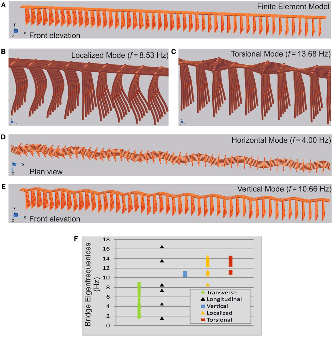
Figure 2. Analyses of the first 100 eigenmodes of the San Saba Bridge. (A) Finite element model of the “millipede-like” bridge structure implemented in Strand7. (B) Localized mode at frequency f = 8.53 Hz. The upper deck of the bridge acts as a waveguide, while relative large amplitude vibrations are localized in the pillars. (C) Torsional mode, f = 13.68 Hz. (D) Horizontal flexural mode involving transverse displacement of the upper deck; f = 4.00 Hz. (E) Vertical flexural mode involved in the bridge failure; f = 10.66 Hz. (F), Eigenfrequencies of the five types of vibration modes: transverse flexural and longitudinal horizontal modes, vertical, localized in the supporting pillars and torsional.
Analysis of the San Saba Bridge Failure
In elastic waveguides, the notion of Floquet–Bloch waves is commonly used (Mead, 1970; Graff, 1991; Brun et al., 2013b) to describe the rate of transmission of energy and to visualize the vibrating structure. Such waves are also proved to be essential in understanding the failure of systems with embedded structural elements like lattices (Slepyan and Troyankina, 1984; Marder and Gross, 1995; Fineberg and Marder, 1999; Slepyan, 2010) or supporting pillars (Brun et al., 2013a) as common for long bridges. Namely, the dispersion relations for Floquet–Bloch waves are embedded into the structure of the Wiener–Hopf equation that describes propagation of a failure wave, which may occur in the form of fracture or a transition wave. In the particular case of the San Saba Bridge, when we refer to two different phases, these are the intact bridges in front of the moving failure region and the bridge devoid of its support behind the failure front. The transition can excite elastic waves propagating in both directions. In this case, the bridge can be compared to a flexural elastic beam rested on an elastic foundation (continuous or discrete as in Figures 3D,E).
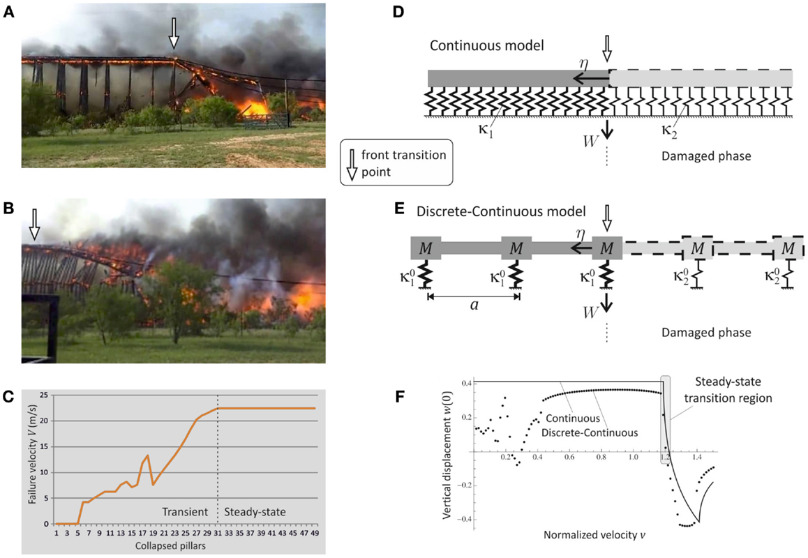
Figure 3. The collapse of San Saba Bridge. Snapshots of the bridge failure: (A) The initial transient regime, (B) the consequent steady-state regime. (C) Failure velocity V shown as a function of the front failure position (number of collapsed pillars). Steady-state propagation is reached when the pillar no. 31 collapses. (D,E) Structural models adopted for the analysis of the steady-state propagation of the failure wave [linear density ρ (kg/m), bending stiffness D (N ⋅ m2)]. (D) Continuous beam on continuous elastic foundation [stiffness per unit length κ1,2 (N/m2), before and after failure, respectively]. (E) Discrete–continuous model on discrete elastic foundation [participating mass M (kg), and stiffness (N/m)]. (F) Normalized vertical displacement w at the transition point η = 0 as a function of the normalized velocity v for the continuous (D) and discrete–continuous (E) structural models (see the Section “Three Dynamic Regimes of Interfacial Waves” in Supplementary Material for the normalization). Steady-state propagation of the failure is possible only in the intersonic velocity interval .
In the framework of fracture mechanics, we consider the failure wave as a “negative exfoliation” of the bridge from its support, where the bridge is represented as a heavy string on a rigid foundation (Figure 5). In this case, not only the critical force but also the energy release rate can play the role of the transition criterion.
The observation of the failure of the San Saba Bridge suggests that two main stages can be identified: (1) the transient accelerating propagation of the failure (Figure 3A) and (2) the steady-state regime (Figure 3B), where the speed of the failure wave is approximately constant. The velocity of propagation of the failure wave in Figure 3C shows that the steady-state regime is reached after the failure of the first 31 pillars.
Whereas the first transient stage (shown in Figure 3A) is a highly complex non-linear phenomenon, the steady-state regime can be analyzed in relatively simple analytical terms. It also appears that the structure would be substantially damaged by the time the steady regime is reached and any attempt to stop the propagation of the failure wave should be made at the initial transient stage.
Theoretically, we consider the steady-state regime. The propagation of a failure wave is modeled for an infinite beam supported by a (non-homogeneous) piecewise continuous elastic foundation (Figure 3D). As a result of the damage, the stiffness of the left and right parts of the foundation is different. The prediction of this simple continuous model has a good applicability to the cases when the bridge structure is of a semi-discrete nature and the supporting elements are distributed periodically (Figure 3E). The speed of a steady-state propagation of the interphase damage appears to be well identified by the continuous model as shown in Figure 3F. On the other hand, transient stage requires more insight, which is gained via the semi-discrete model involving point masses at the junction points as well as distributed inertia along the flexural beam.
Results
Evaluation of the Speed of the Failure Wave
The solution leads to the expression of the vertical flexural displacement W (0) (see Figures 3D,E) measured in the moving system of coordinates centered at the front of the transition wave:
where κ1 and κ2 < κ1 are the stiffness of the supporting pillars on the left (before collapse) and on the right (collapsed) parts with respect to the moving front transition point η = 0, g is the gravitational force, and ρ the linear density of the beam structure (see Figure 3D).
The generic approach applies to a wide range of parameters of elastic systems and hence the results are linked to characteristic length ξ = (D/κ1)1/4 and time with D, the bending stiffness of the beam (see Figures 3D,E). Three velocity regimes are present: subsonic , intersonic , and supersonic . In particular, the important regime is identified for the intersonic propagation as the steady-state corresponding to w(0) ≥ 0, which is a monotonically decreasing function of the crack speed. In particular, when w(0) = 0 we have
which becomes in the limit of a complete failure of the damaged foundation (i.e., κ2 → 0) as in Figure 4 and in Eq. (1). The analytical model of Brun et al. (2013a) predicts the speed of steady propagation to be in the left neighborhood of the upper limit . In the following, we will show that the predicted speed matches amazingly with the observation recorded during the failure of the bridge.
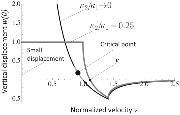
Figure 4. Vertical displacement w(0) at the failure point as a function of the velocity v. The curves are shown for stiffness ratios κ2/κ1 → 0 (similar to the real bridge) and κ2/κ1 = 0.25. The velocity , corresponding to w(0) = 0 is an upper limit for the steady-state velocity of propagation. Steady-state propagation is possible only in the intersonic velocity regime, the velocity interval where the curves are monotonically decreasing. The steady-state failure configuration (Figure 3B) shows that the vertical displacement w(0) is of small magnitude and the critical velocity is in the left neighborhood of .
Resonance Modes and “Insignificant” Flexural Vibrations
A direct transient analysis for a failing bridge would involve a large-scale computational model and is not considered to be feasible in the engineering practice. Of course, the choice of initial conditions and evolution of the structure becomes an important and challenging part of the computational procedure. A conventional engineering approach would allow an extensive and detailed analysis of eigenfrequencies and resonant modes. How useful would this information be in the circumstances related to San Saba Bridge?
To answer this question, we have done a complete eigenfrequency analysis in the framework of an FEM based on the industrial grade tool Strand7. The computational model has not been simplified in any way, and every technical detail has been embedded in a full three-dimensional FEM computational domain as shown in Figure 2A. The details of computational parameters are supplied in the supplementary material. The computed eigenfrequencies accurately represent the resonant vibrations of the actual San Saba Bridge.
For an undamaged structure, the vertical flexural modes would not attract much significant attention of a Structural Engineer, since they correspond to relatively high-frequency range (f = 10.4–11.1 Hz) compared to the modes involving a horizontal motion of the upper deck of the bridge (f = 1.6–8.9 Hz). In Figure 2, the first types of eigenmodes are shown: an example of a transverse flexural mode is represented in Figure 2D, a mode where vibrations are localized within the supporting beam is shown in Figure 2B, a typical torsional mode is reported in Figure 2C and, finally, a vertical flexural mode is given in Figure 2E. The overall diagram with eigenfrequencies (Figure 2F) suggests that the vertical flexural vibrations would be in the highest frequency range among the identified vibrations. The three-dimensional computation has revealed that the low-frequency vibrations of the San Saba Bridge correspond to horizontal modes, transverse (Figure 2D) and longitudinal. On the contrary, the vertical flexural vibrations (Figure 2E) occur in a narrow band at much higher frequencies and also take into account the effect of the longitudinal stiffness of the supporting pillars. The corresponding resonance frequencies are in the same range of the frequencies associated with localized vibration of the pillars (f = 8.5–10.6 Hz) and torsional vibrations (f = 10.9–14.4 Hz), making difficult to distinguish different eigenmodes.
Discussion
Prediction of the Speed of the Transition Wave
The first impression gained from the computational model is that the vertical flexural motion is less relevant to the identification of dangerous vibrations within the dynamic design process, and the main attention should be given to the low-frequency transverse modes. As follows from the physical evidence, the vertical flexural mode that is driven by gravitational forces, is the one, which leads to a failure wave. This also suggests that the standard, although advanced, engineering techniques would not lead to the right conclusion in the explanation of the failure wave in the San Saba Bridge. However, the information provided by the finite element computations, combined with the knowledge of flexural Bloch waves, leads to the correct answer, and prediction of the steady regime also includes an accurate estimate of the speed of the failure wave. The comparison between the FEM and the simplified waveguide model for an elastic beam structure, supported by the elastic foundation (Figures 3D,E), shows that the parameters of the system are chosen so that the frequencies generated by FEM (Figure 2F) match well with the pass band interval identified for Floquet–Bloch waves in the periodic waveguide model (Brillouin, 1953; Brun et al., 2013a).
The movie taken for the wooden section of the San Saba Bridge, together with the measurements, show that the length of the failed section is around 209 m, and the speed of the steady-state propagation approaches V = 22.4 m/s (see Figure 3C). To compare with the analytical model, we require the evaluation of the internal unit length ξ = 0.382 m and unit time τ = 0.157 × 10⁻¹ s, which has been estimated form the FEM implementation as detailed in the supplementary material (in Figures 3D,E the parameters are: a = 4.26 m, D = 0.8 × 10⁶ Nm2, κ1 = 37.5 MPa, κ2 → 0, ρ = 9.23 × 10³ kg/m). The interphase wave speed for the failing bridge appears to be which is exactly within the predicted range, as shown in Figures 3F and 4.
It is noted that an extremely complex phenomenon, which is transient and highly non-linear, has been explained in the framework of the propagating failure wave. On a practical note, it is also worth mentioning that the initial transient stage would allow an intervention by “removing certain sections of the bridge” and hence stopping the propagation of the fault.
Configurational Force Accompanying the Bridge Failure
We have shown that the failure wave speed is bounded by speeds of the flexural waves, which can propagate in front and behind the transition point.
A simplified model based on the analysis of an inextensible string on a rigid foundation (Figure 5) shows that the energy release rate can be considered as the transition criterion similarly to that used in fracture mechanics (Slepyan, 1981, 2002). This approach gives an elegant and explicit approximation of the force acting on failing bridge at the front of the transition wave. Such a force is the Eshelby configurational force (Eshelby, 1951; Maugin, 1993; Bigoni et al., 2014).
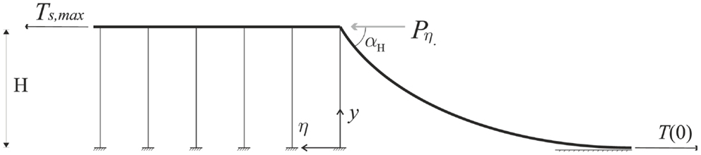
Figure 5. Inextensible non-linear string model of the bridge structure is shown. The string is subjected to tension T(y) = T(0) + ρgy, where ρ is the linear density and g is the gravitational force. At steady-state regime of failure propagation, the configurational force Pη = ρgH is the energy release rate Gη, independent of the velocity v.
The horizontal configurational force (as in Figure 5) acting at the transition front is equal to
It is independent of the speed of the transition wave, and is simply the potential energy with respect to the ground level. Furthermore, by adding the condition ρgH = Gc, where Gc stands for the critical energy release rate required to fail a single section of the bridge, we observe that if ρH is maintained below Gc/g the failure will not propagate, and, as expected, the lighter and lower structure appears to be more resistant to failure compared to heavier and taller bridge systems.
Both linear and non-linear regimes of the transition wave of failure are fully covered by the model presented here. The formulae (1) and (3) for the velocity of failure propagation are simple and accurate, but their derivation is highly non-trivial and cannot be achieved by an intuitive ad hoc effort. Availability of the experimental data was a unique occurrence for a large-scale failure such as the widely featured in press San Saba Bridge. The theory, which is in full agreement with the observational data, paves the way to the design of highly robust and dynamically resistant structures, which includes long bridges and skyscrapers.
Conflict of Interest Statement
The authors declare that the research was conducted in the absence of any commercial or financial relationships that could be construed as a potential conflict of interest.
Acknowledgments
Alexander B. Movchan, Michele Brun, and Leonid I. Slepyan acknowledge the financial support of the European Community’s Seven Framework Programme under contract numbers PIAP-GA-2011-286110-INTERCER2, PIEF-GA-2011-302357-DYNAMETA, and IAPP-2011-284544-PARM-2, respectively. Gian Felice Giaccu and Michele Brun acknowledge the financial support of the Regione Autonoma della Sardegna (LR 7 2010, grant “M4” CRP-27585).
Supplementary Material
The Supplementary Material for this article can be found online at http://www.frontiersin.org/Journal/10.3389/fmats.2014.00012/abstract
References
Abraham, F. D., and Gao, H. (2000). How fast cracks propagate? Phys. Rev. Lett. 84, 3113. doi: 10.1103/PhysRevLett.84.3113
Balk, A., Cherkaev, A., and Slepyan, L. (2001). Dynamics of chains with non-monotone stress-strain relations. I. Model and numerical experiments. J. Mech. Phys. Solids 49, 131–148. doi:10.1016/S0022-5096(00)00026-0
Bartelt, P., Buser, O., and Platzer, K. (2006). Fluctuation-dissipation relations for granular snow avalanches. J. Glaciol. 52, 631–643. doi:10.3189/172756506781828476
Bigoni, D., Bosi, F., Dal Corso, F., and Misseroni, D. (2014). Instability of a penetrating blade. J. Mech. Phys. Solids 64, 411–425. doi:10.1016/j.jmps.2013.12.008
Brun, M., Giaccu, G. F., Movchan, A. B., and Movchan, N. V. (2012). Asymptotics of eigenfrequencies in the dynamic response of elongated multi-structures. Proc. R. Soc. Lond. 468, 378–394. doi:10.1098/rspa.2011.0415
Brun, M., Movchan, A. B., and Slepyan, L. I. (2013a). Transition wave in a supported heavy beam. J. Mech. Phys. Solids 61, 2067–2085. doi:10.1016/j.jmps.2013.05.004
Brun, M., Movchan, A. B., Jones, I. S., and McPhedran, R. C. (2013b). Bypassing shake, rattle and roll. Phys. World 26, 32–36.
Brun, M., Movchan, A. B., and Jones, I. S. (2013c). Phononic band gap systems in structural mechanics: slender elastic structures versus periodic waveguides. J. Vib. Acoust. 135, 041013. doi:10.1115/1.4023819
Cherkaev, A., Cherkaev, E., and Slepyan, L. (2005). Transition waves in bistable structures. I. Delocalization of damage. J. Mech. Phys. Solids 53, 383–405. doi:10.1016/j.jmps.2004.08.002
Craster, R. V., Kaplunov, J., and Postnova, J. (2010). High-frequency asymptotics, homogenisation and localisation for lattices. Q. J. Mech. Appl. Math. 63, 497–519. doi:10.1093/qjmam/hbq015
Eshelby, J. D. (1951). The force on an elastic singularity. Philos. Trans. R. Soc. Lond. A 244, 87–112. doi:10.1098/rsta.1951.0016
Fineberg, J., and Marder, M. (1999). Instability in dynamic fracture. Phys. Rep. 313, 1–108. doi:10.1016/S0370-1573(98)00085-4
Heierli, J., Gumbsch, P., and Zaiser, M. (2008). Anticrack nucleation as triggering mechanism for snow slab. Science 321, 240–243. doi:10.1126/science.1153948
Marder, M., and Gross, S. (1995). Origin of crack tip instabilities. J. Mech. Phys. Solids 43, 1–48. doi:10.1016/0022-5096(94)00060-I
Mead, D. J. (1970). Free wave propagation in periodically supported infinite beams. J. Sound Vib. 11, 181–197. doi:10.1016/S0022-460X(70)80062-1
Movchan, A. B., and Slepyan, L. I. (2007). Band gap Green’s functions and localized oscillations. Proc. R. Soc. Lond. A 463, 2709–2727. doi:10.1098/rspa.2007.0007
Pendry, J. B. (2000). Negative refraction makes a perfect lens. Phys. Rev. Lett. 85, 3966. doi:10.1103/PhysRevLett.85.3966
Slepyan, L., Cherkaev, A., and Cherkaev, E. (2005). Transition waves in bistable structures. II. Analytical solution: wave speed and energy dissipation. J. Mech. Phys. Solids 53, 407–436. doi:10.1016/j.jmps.2004.08.001
Slepyan, L. I. (2010). Wave radiation in lattice fracture. Acoust. Phys. 56, 962–971. doi:10.1134/S1063771010060217
Slepyan, L. I., and Troyankina, L. V. (1984). Fracture wave in a chain structure. J. Appl. Mech. Tech. Phys. 25, 921–927. doi:10.1007/BF00911671
Stronge, W. J. (1987). The domino effect: a wave of destabilizing collisions in a periodic array. Proc. R. Soc. Lond. 409, 199–208. doi:10.1098/rspa.1987.0013
Keywords: transition waves, dynamics, structural mechanics, Wiener–Hopf functional equation, failure analysis
Citation: Brun M, Giaccu GF, Movchan AB and Slepyan LI (2014) Transition wave in the collapse of the San Saba Bridge. Front. Mater. 1:12. doi: 10.3389/fmats.2014.00012
Received: 03 July 2014; Paper pending published: 22 July 2014;
Accepted: 06 August 2014; Published online: 01 September 2014.
Edited by:
Davide Bigoni, University of Trento, ItalyReviewed by:
Francesco Dal Corso, University of Trento, ItalyAndrea Piccolroaz, University of Trento, Italy
Copyright: © 2014 Brun, Giaccu, Movchan and Slepyan. This is an open-access article distributed under the terms of the Creative Commons Attribution License (CC BY). The use, distribution or reproduction in other forums is permitted, provided the original author(s) or licensor are credited and that the original publication in this journal is cited, in accordance with accepted academic practice. No use, distribution or reproduction is permitted which does not comply with these terms.
*Correspondence: Alexander B. Movchan, Department of Mathematical Sciences, University of Liverpool, Peach Street, L69 7ZL Liverpool, UK e-mail: abm@liverpool.ac.uk