Intrasulcal electrocorticography in macaque monkeys with minimally invasive neurosurgical protocols
- 1 Department of Physiology, Niigata University School of Medicine, Niigata, Japan
- 2 Department of Neurosurgery, The University of Tokyo Graduate School of Medicine, Tokyo, Japan
- 3 Center for Transdisciplinary Research, Niigata University School of Medicine, Niigata, Japan
- 4 Department of Physiology, The University of Tokyo Graduate School of Medicine, Tokyo, Japan
- 5 Graduate School of Information Science and Technology, The University of Tokyo, Tokyo, Japan
- 6 Department of Anatomy, Niigata University School of Medicine, Niigata, Japan
- 7 National Institute of Neuroscience, National Center of Neurology and Psychiatry, Tokyo, Japan
- 8 Department of Biocybernetics, Graduate School of Science and Techology, Niigata University, Niigata, Japan
Electrocorticography (ECoG), multichannel brain-surface recording and stimulation with probe electrode arrays, has become a potent methodology not only for clinical neurosurgery but also for basic neuroscience using animal models. The highly evolved primate’s brain has deep cerebral sulci, and both gyral and intrasulcal cortical regions have been implicated in important functional processes. However, direct experimental access is typically limited to gyral regions, since placing probes into sulci is difficult without damaging the surrounding tissues. Here we describe a novel methodology for intrasulcal ECoG in macaque monkeys. We designed and fabricated ultra-thin flexible probes for macaques with micro-electro-mechanical systems technology. We developed minimally invasive operative protocols to implant the probes by introducing cutting-edge devices for human neurosurgery. To evaluate the feasibility of intrasulcal ECoG, we conducted electrophysiological recording and stimulation experiments. First, we inserted parts of the Parylene-C-based probe into the superior temporal sulcus to compare visually evoked ECoG responses from the ventral bank of the sulcus with those from the surface of the inferior temporal cortex. Analyses of power spectral density and signal-to-noise ratio revealed that the quality of the ECoG signal was comparable inside and outside of the sulcus. Histological examination revealed no obvious physical damage in the implanted areas. Second, we placed a modified silicone ECoG probe into the central sulcus and also on the surface of the precentral gyrus for stimulation. Thresholds for muscle twitching were significantly lower during intrasulcal stimulation compared to gyral stimulation. These results demonstrate the feasibility of intrasulcal ECoG in macaques. The novel methodology proposed here opens up a new frontier in neuroscience research, enabling the direct measurement and manipulation of electrical activity in the whole brain.
Introduction
Cerebral cortex is intricately folded in many primate species. In humans, two-thirds of the cerebral cortex is buried in grooves, known as the cerebral sulci, whereas only one-third of the cortex is exposed in the cerebral gyri (Ribas, 2010). Similarly, in macaque monkeys, approximately half of the neocortex lies within the cerebral sulci (Felleman and Van Essen, 1991). Functional magnetic resonance imaging (fMRI) and positron emission tomography have revealed neural activation related to important functions such as cognition and attention in intrasulcal as well as gyral regions of the cerebral cortex (Tsao et al., 2003; Beauchamp et al., 2004; Koyama et al., 2004). These neuroimaging techniques, however, have difficulty obtaining precise spatiotemporal profiles of intrasulcal activity simultaneously with millimeter source localization and millisecond temporal resolution. On the other hand, extracellular spike recording is a widely used tool for investigating cortical functions at the level of single neurons (Mountcastle, 1957). Extracellular single neuronal activities also provide an efficient input for driving artificial effectors of neuroprosthetics (Hatsopoulos and Donoghue, 2009). However, repeated intrasulcal penetration of the microelectrode (Tomita et al., 1999) inevitably cause unintended damage to the intervening brain tissues in the course of recording sessions over months. Furthermore, when the microelectrode was chronically implanted, neural signals might possibly be lost after long period of time due to the isolation of the electrode’s tip by glial cells (Polikov et al., 2005). Ideally, direct access to the intrasulcal cortices without damaging the surrounding tissues could enable stable recording from and stimulation to these regions in physiological conditions, advancing our understanding of the fundamental cerebral functions in situ.
A promising candidate is electrocorticography (ECoG), which was originally developed as a clinical tool for monitoring and mapping during neurosurgery. ECoG is now recognized as a well-balanced methodology for basic neurophysiological investigations (Leuthardt et al., 2006; Fisch et al., 2009; Liu et al., 2009; Rubehn et al., 2009). Compared to scalp electroencephalography, ECoG has much better signal fidelity and spatial resolution (Leuthardt et al., 2006; Miller et al., 2009; Slutzky et al., 2010; Toda et al., 2011). In addition, compared to microelectrode recordings, ECoG has the advantage of recording local field potentials (LFPs) less invasively, with superior long-term stability (Rubehn et al., 2009; Chao et al., 2010). Recently various frequency components of LFP have been implicated in carrying informative sensory, motor, and cognitive signals across brain regions (Buschman and Miller, 2007; Liu et al., 2009), which further emphasizes the importance of ECoG. Nonetheless, the placement of ECoG arrays is usually limited to the surface of the brain. One previous report described the placement of ECoG arrays within the bank of the human central sulcus (CS; Yanagisawa et al., 2009). However, intrasulcal ECoG recording/stimulation in macaque monkeys, the most prevailing animal model for investigation of cognitive brain functions, is technically demanding, since the brain volume in macaque is less than one-tenth that of humans. To achieve intrasulcal ECoG in macaques, highly interdisciplinary approaches combining neurosurgery, neuroengineering, and neurophysiology would be required.
In the current study, we sought to develop surgical protocols for placing custom-designed ECoG probes for electrophysiological recording and stimulation within the cerebral sulci of macaque monkeys. The utility of our method was tested in two experiments. First, we evaluated the feasibility of intrasulcal ECoG recording. We designed an ultra-thin ECoG probe for macaques using micro-electro-mechanical systems (MEMS) technology (Toda et al., 2011), and tested whether visually evoked ECoG signals could be reliably recorded from the ventral bank of the superior temporal sulcus (STS), comparable to the signals from the surface of the inferior temporal gyrus (ITG). Second, we attempted direct stimulation of the intrasulcal cortex using a modified clinical-use ECoG probe. We compared the stimulation thresholds for muscle twitch between intrasulcal and gyral regions in the primary motor cortex (M1).
Materials and Methods
General Surgical Procedures
Three male macaque monkeys (two Macaca fuscata and one M. mulatta), weighing 6–9 kg were used for the intrasulcal ECoG recording experiment, in accord with the NIH Guidelines for the Care and Use of Laboratory Animals. The experimental protocol was approved by the Niigata University Institutional Animal Care and Use Committee. After premedication with ketamine (50 mg/kg) and medetomidine (0.03 mg/kg), each animal was intubated with an endotracheal tube of 6 or 6.5 mm and connected to an artificial respirator (A.D.S.1000, Engler Engineering Corp., FL, USA). The venous line was secured using lactated Ringer’s solution, and ceftriaxone (100 mg/kg) was dripped as a prophylactic antibiotic. Postoperatively, the monkeys received ketoprofen as an analgesic for 3 days, and antibiotics were continued for 1 week after surgery. Body temperature was maintained at 37°C using an electric heating mat. A vacuum fixing bed (Vacuform, B.u.W.Schmidt GmbH, Garbsen, Germany) was used to maintain the position of the body. Oxygen saturation, heart rate, and end-tidal CO2 were continuously monitored (Surgi Vet, Smiths Medical PM Inc., London, UK) throughout surgery to adjust the levels of anesthesia. The skull was fixed with a three-point fastening device (Integra Co., NJ, USA) with a custom-downsized attachment for macaques (Figure 1A). In the intra-dural operation, we used a microscope (Ophthalmo-Stativ S22, Carl Zeiss Inc., Oberkochen, Germany) with a CMOS color camera (TS-CA-130MIII, MeCan Imaging Inc., Saitama, Japan).
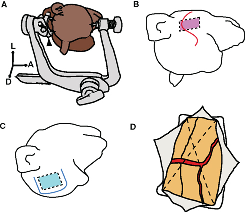
Figure 1. Skull fixation and craniotomy. (A) Illustration of head positioning with a three-point fastening device. Black arrowhead indicates a customized attachment for macaques. A, anterior; L, left; D, dorsal. (B) S-shaped skin incision indicated by red line. Red rectangle indicates the range of the craniotomy for the superior temporal sulcus (STS). (C) U-shaped skin incision indicated by blue line. Blue square indicates the range of craniotomy for the central sulcus (CS). (D) Dural incision (dotted lines) into four quadrants. Each quadrant was retracted toward the margin of the craniotomy.
For the intrasulcal stimulation experiment, three male macaque monkeys (two M. fuscata and one M. mulatta) weighing 6–9 kg were used. All surgical and experimental protocols were in full compliance with the regulations of The University of Tokyo School of Medicine and with the NIH Guidelines for the Care and Use of Laboratory Animals. Surgery was conducted in aseptic conditions under general anesthesia with sodium pentobarbital (5 mg/kg/h). The skull was fixed using a stereotactic frame (Narishige, Tokyo, Japan). Postoperatively, the monkeys received ketoprofen for 3 days as an analgesic, and ampicillin for 1 week as an antibiotic. We used a microscope (OPMI Sensera, Carl Zeiss Inc., Oberkochen, Germany) with a color video camera (DXC-C1, Sony Co., Tokyo, Japan) during microsurgery.
Skin Incision and Craniotomy
In the operation for ECoG recording, following an S-shaped incision (Figure 1B), we dissected the layer between the skin and the muscle. The muscle was retracted forward while the skin was retracted downward, to secure a sufficient operative field. The target location and the size of the craniotomy were determined by preoperative MRI. The size of the craniotomy was 35 mm × 25 mm, and the zygomatic arch was removed to facilitate the approach. Four burr holes were opened by a perforator [Primado (PD-PER), NSK, Tochigi, Japan] with an attachment for infants (DGR-OS Mini 8/5 mm R, Acura-Cut Inc., MA, USA) (Movie S1 in Supplementary Material). After the bone and the dura mater were separated using an elevator, the skull was cut with a craniotome [Primado (PD-CRA), NSK, Tochigi, Japan], and the bone flap was removed. The range of craniotomy on the ventral edge was expanded by luer bone rongeur. Hemorrhage from the dura was controlled by a bipolar coagulator (Bipolar SX-2001, Tagawa Electronic Research Institute, Chiba, Japan). During the operation of the monkeys for the ECoG stimulation experiment, after a U-shaped skin incision (Figure 1C), a 30 mm × 35 mm craniotomy was made by drilling.
Dural Incision
We cut the dura mater in two steps. Initially, we cut the surface layer of the dura with a 21-gage injection needle. We then raised the edge of the surface layer and cut the lower layer of the dura. The subdural space was secured by raising up the whole dura layer. To prevent cortical damage, we inserted surgical cotton sheets (Bem-sheets, Kawamoto Co., Osaka, Japan) into the subdural space. The dura was cut with scissors into four quadrants (Figure 1D), each of which was then retracted toward the margins of the craniotomy. Thus, oozing from the epidural space was effectively stopped and the operative field was kept clear throughout the operation.
Intra-Dural Microsurgery
All of the cortical surfaces except for the target sulcus were covered with wet surgical cotton sheets to prevent mechanical damage or drying. We used surgical cotton sheets or absorbable gelatin sponge (Gelfoam, Pfizer, NY, USA) as cushioning material between the surgical devices and brain tissue. We cut the surface arachnoid membrane near the blood vessel, utilizing the perivascular space (Figure 2A). A 27-gage injection needle (Figure 2B) was suitable for the first cut of the arachnoid. We held the edge of the incised arachnoid with No. 0 biceps, and made sharp dissections using microscissors (Figure 2C). When tension was added in the appropriate direction to open the sulcus, arachnoid trabeculae (Figure 2D, white arrow head) appeared between the banks. These were cut sharply with microscissors until the fundus was reached, to make a space for the electrode (Figures 2E,F). Importantly, we were careful to withdraw the vessels to the correct side to which they belonged. To avoid venous congestion or brain edema, we never cut or coagulated the veins even if the veins were perfused from both sides.
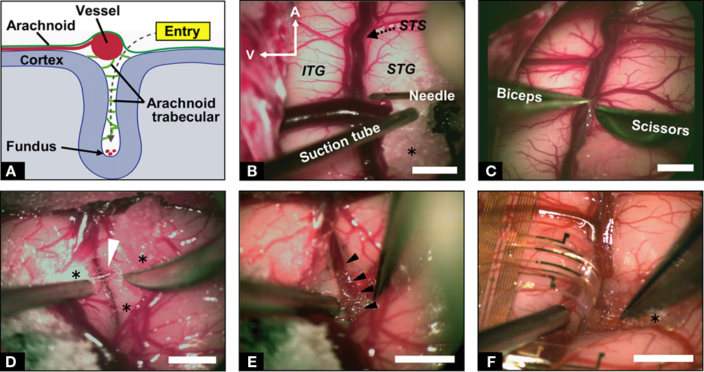
Figure 2. Microdissection for implanting ECoG probe. (A) Schematic illustration of the coronal route of dissection from the entry point to the fundus of the sulcus. (B) Microscopic view of the left temporal lobe of the macaque monkey. Microdissection started near the vessels with a 27-gage injection needle. A, anterior; V, ventral; STS, superior temporal sulcus; ITG, inferior temporal gyrus; STG, superior temporal gyrus; asterisk indicates surgical cotton. (C) Sharp cutting of the arachnoid membrane. (D) Exposure of trabecular connective tissues (white arrowhead) between the upper and lower banks of STS with careful retraction of the lower bank. (E) Observation of microvessels at the fundus of the STS (black arrowheads). (F) A branch of the electrocorticographic (ECoG) probe inserted into the sulcus. Approximately 7 mm of the probe was inserted in depth. Scale bars indicate 5 mm.
Electrode Array
We designed a 20-μm-thick Parylene-C-based 128-channel gold electrode array (Figure 3A) covering 20 mm × 40 mm for recording from STS (Figures 3B–D). The basic structures and fabrication processes of the probe have been described elsewhere (Toda et al., 2011). The probe array contained 8 × 16 electrodes with 2.5-mm inter-electrode spaces. At each electrode, a square of the gold surface was exposed (100 μm × 100 μm; Figure 3A, inset). The probe was two-sided comb-like shaped, with eight branches protruding from each side of the main trunk (Figure 3A). We also used clinical-use silicone-coated electrode arrays downsized for stimulating the CS in monkeys (Figure 4). A double-faced electrode (Figure 4A; 1 × 5 array in one side; platinum; 3 mm diameter, 1.5 mm diameter of electrode contact, 5 mm inter-electrode distance with total thickness of 1.2 mm; Unique Medical Co., Tokyo, Japan) was implanted within the CS of two monkeys, while a 20-grid electrode (4 × 5 array; platinum; 3 mm diameter, 1.5 mm diameter of electrode contact, 5 mm inter-electrode distance; Unique Medical Co., Tokyo, Japan) was placed subdurally over the precentral gyrus and postcentral gyrus of one monkey.
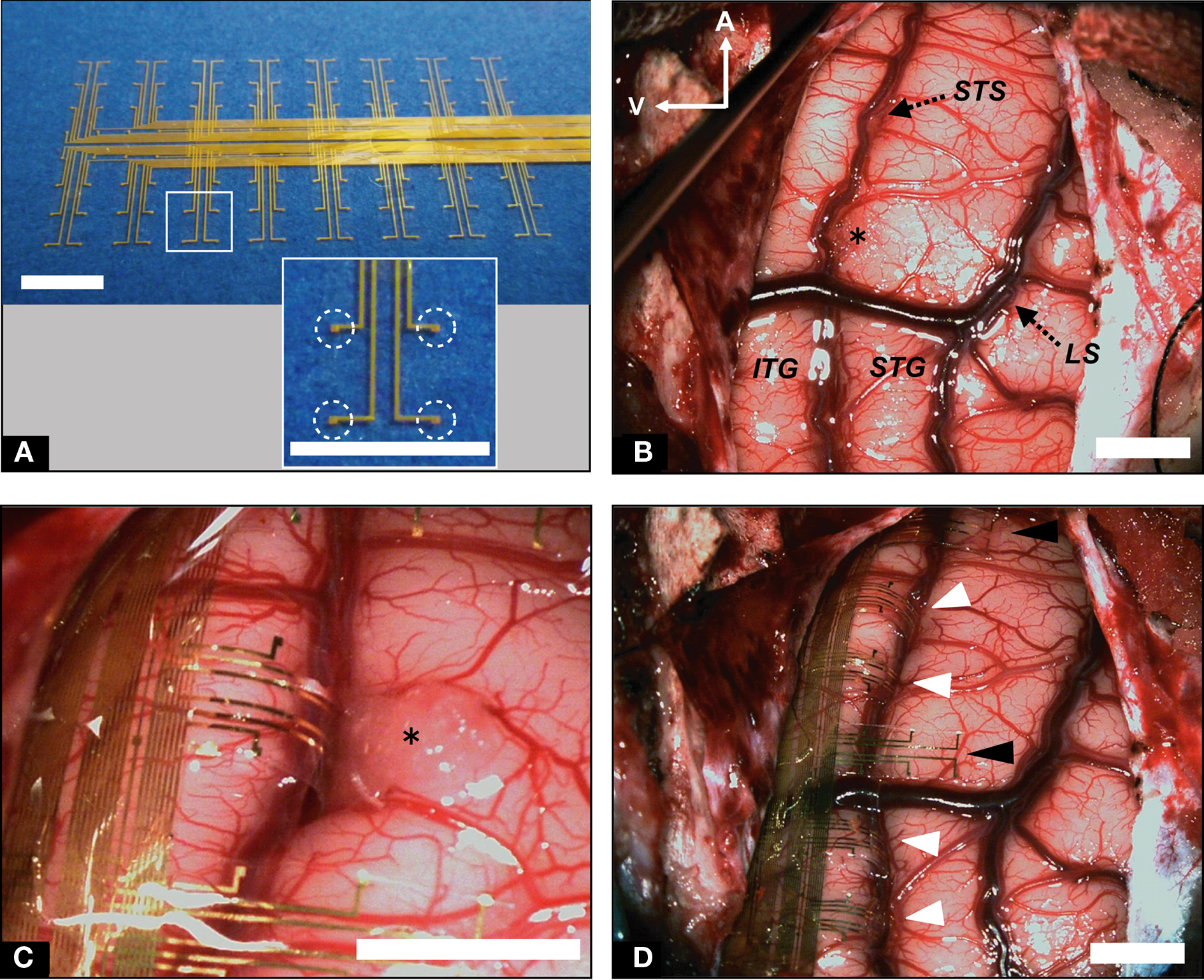
Figure 3. Implantation of recording ECoG probe into STS and ITG. (A) Flexible electrode array to be implanted into STS. Individual electrode contacts are shown in the inset (dotted circles). (B) Low-magnification view of the left temporal lobe before probe implantation. STS was dissected from surface to bottom; LS, lateral sulcus. (C) High-magnification view of probe branches fitted to STS and ITG. (D) Low-magnification view of the left temporal lobe following implantation of electrode array. White arrowheads indicate probe branches inserted into STS. Black arrowheads denote branches on the surface of the STG. Scale bars indicate 5 mm.
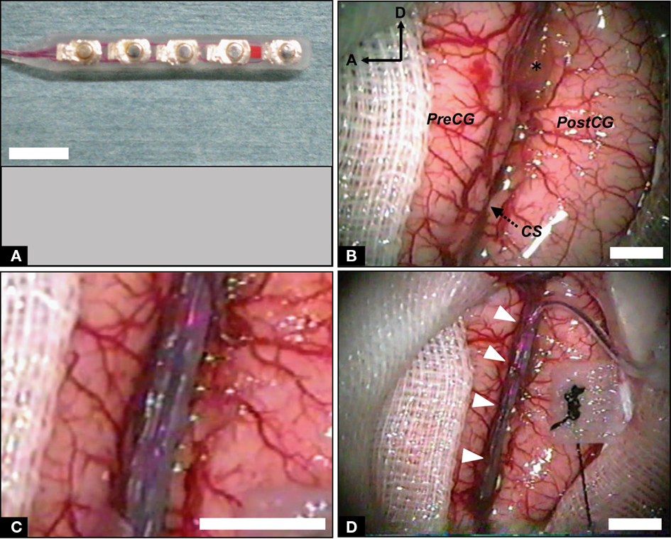
Figure 4. Implantation of stimulating ECoG probe into intrasulcal M1. (A) Double-faced silicone electrode array. (B) Photograph of the left fronto-parietal lobes before probe implantation. The CS was dissected from surface to bottom. PreCG, precentral gyrus; PostCG, postcentral gyrus; A, anterior; D, dorsal; asterisk, surgical cotton. (C) High-magnification view of the CS with inserted electrode array. (D) Low-magnification view of the CS following implantation of the probe. White arrowheads indicate the bridging veins preserved carefully. Scale bars, 5 mm.
Electrode Array Implantation
We placed the electrode array carefully into the sulcus, confirming that the probe had not been bent (Figure 2F). Importantly, we were careful to fit the electrode array to the brain surface without stress. When there were superficial bridging veins between the banks of the sulcus, we either displaced the electrode’s branches to avoid them (Figure 3D), or passed the probe under the vessels (Figure 4D, white arrow heads). We opened the STS by 30 mm (Figure 3B) and a sufficient depth to reach the bottom (5–9 mm). We also opened the CS by 40 mm (Figure 4B). We maintained a clear operative field without blood through the surgery to prevent postoperative chemical meningitis.
Closing the Craniotomy
When the implantation of the electrode array was completed, the entire alignment was adjusted again (Figures 3D and 4D). The lead was fixed with resin on the bone edge. As the dura shrank during the operation, we patched dural defects using the fascia of the temporal muscle with water-tight suturing to prevent surgical complications such as infection or cerebrospinal fluid leakage. The bone flap was then fixed with a titanium plate and titanium screws. Microconnectors (Omnetics, MN, USA) and a connector chamber (Hokuyo, Niigata, Japan) were fixed strongly also with titanium screws. For the cortical stimulation study, connectors were fixed with resin. We sutured layer by layer and the operation was finished.
Recording
Two monkeys (monkey B and F) were trained in a visual fixation task to keep their gaze within ±1° of visual angle of a fixation target (0.3° diameter). Eye movements were captured with an infra-red camera system (i-rec1) at a sampling rate of 60 Hz. The stimuli were presented on a 15-inch CRT monitor (NEC, Tokyo, Japan) at a viewing distance of 26 cm. After 450 ms of stable fixation, the stimulus was presented for 300 ms followed by a 600-ms blank interval. Between two and five stimuli were presented successively in a single trial. Monkeys were rewarded with a drop of apple juice for maintaining fixation over the entire duration of the trial. We used 24 photographs of objects from a wide variety of categories, including faces, foods, houses, cars, etc. The long axis of each stimulus subtended 6° of visual angle. For monkey B, stimuli were presented with an x86 PC running a custom-written OpenGL-based stimulation program under Windows XP. Behavioral control for the experiments was maintained by a network of interconnected PCs running QNX real-time OS (QSSL, ON, Canada), which controlled the timing and synchronization. Data was online-monitored and stored on a PC-based system (NSCS, Niigata, Japan). For monkey F, stimuli were presented with a ViSaGe visual stimulus generator (Cambridge Research Systems, Rochester, UK). Task control and data monitoring/storing were maintained by System 3 Real-time Signal Processing Systems (Tucker Davis Technologies, FL, USA).
Electrocorticography signals were differentially amplified using a 128-channel amplifier (Tucker Davis Technologies, FL, USA for monkey F, and Plexon, TX, USA for monkey B) with high- and low-cutoff filters (for monkey B, 300 Hz and 1.0 Hz, respectively; for monkey F, 400 and 1.5 Hz, respectively). All subdural electrodes were referenced to the titanium head restraint post or the titanium connector chamber, which was attached directly to the dura. Signals were recorded at a sampling rate of 1 kHz per channel for monkey B or 2 kHz per channel for monkey F. Signals recorded at 2 kHz were resampled at 1 kHz before the analyses. Electrode impedance was typically 3–5 kΩ. Electrodes with impedance greater than 3 MΩ, possibly due to wiring disconnection at the connector were excluded from the analyses.
For power spectral analysis, data were recorded over a 2-s epoch in each intertrial interval. Data from 96 or 51 two-second epochs were collected from monkey B and F, respectively. The data were segmented into sections, in 256-point windows. Each was Hann-windowed and Fourier transformed with 512 fast Fourier transform (FFT) points. The power spectral density (PSD) was defined as the average over epochs.
The signal-to-noise ratio (SNR) was defined as the ratio of the root mean square (RMS) in the stimulus presentation period to RMS in the prestimulus period in single trials. The data from 50 to 350 ms after onset of the stimulus presentation was used as “signal” and the data from −300 to 0 ms was used as “noise.” SNRs were averaged across trials for each channel.
For all analyses, we used in-house Matlab (The MathWorks, MA, USA) codes with the open source Matlab toolbox EEGLAB2 and R3.
Stimulation
Electrical stimulation experiments were conducted under anesthesia, induced with an intramuscular injection of ketamine (10 mg/kg) and maintained with continuous intravenous infusion of propofol (5–10 mg/kg/h) during stimulation. Heart rate and oxygen saturation were continuously monitored. Oxygen saturation was kept over 95%. Body temperature was maintained at 37°C using hot-water bags. Glucose-lactated Ringer’s solution was given intravenously (5 ml/kg/h) throughout the experiment. Electrical stimulation was applied in a bipolar fashion to a pair of adjacent electrodes by a programmed digital stimulator (SEN-7103M, Nihon Kohden, Tokyo, Japan) and a stimulus isolator (SS-201J, Nihon Kohden, Tokyo, Japan). Repetitive square-wave electric currents of alternating polarity with a pulse width of 300 μs and a frequency of 50 Hz were delivered for 600 ms. At each electrode site, cortical stimulation began with an amplitude of 0.5 mA, then increased gradually until (1) a maximum of 5 mA was reached or (2) muscle twitches were observed (motor threshold intensity).
Histology
At 4 weeks post-implantation, one animal was deeply anesthetized with a sodium pentobarbital overdose (60 mg/kg, i.v.), then transcardially perfused with 1 L of 0.1 M phosphate-buffered saline (PBS) and 2 L of 4% paraformaldehyde in 0.1 M PBS. The brain was removed from the skull and post-fixed at 4°C for 3 days using the same fixative. Samples processed for paraffin embedding were cut into 5 μm sections with a rotary microtome (LR-85, YAMATO KOHKI, Saitama, Japan), The sections were placed on silane-coated glass slides and stained with hematoxylin and eosin.
Results
Intrasulcal ECoG Recording
We implanted a flexible Parylene-C-based gold electrode array (Figure 3A) into the ventral bank of the STS and the ITG of the macaque monkey. The STS was successfully opened by 30 mm in length, and to a sufficient depth to reach the bottom (5–9 mm; Figures 2E and 3B; Movie S1 in Supplementary Material) by careful dissection under the microscope (Figure 2). Eventually, four to five branches of the probe were implanted into the STS (Figures 3C,D), whereas other branches and the trunk of the probe were placed on the gyral surface of the ITG. On average, microscopic neurosurgery took approximately 3 h, and there was no postoperative complications.
We recorded visually evoked ECoG signals from two hemispheres of two monkeys that had been trained in a visual fixation task. To evaluate the quality of intrasulcal recording, we compared the ECoG signals from the STS (intrasulcal recording) and ITG (surface recording) in two ways (Figure 5A). First, we compared the PSD of the signals. The amplitude of PSD decreased at higher frequencies (Figure 5B) in both locations (STS and ITG). The mean PSD for STS tended to be slightly lower than for ITG. There was a significant effect of frequency band (θ, 4–6 Hz; α, 8–12 Hz; β, 16–28 Hz; γ, 32–64 Hz; high γ, 68–100 Hz) on the mean PSD (p < 10−16, two-way ANOVA). The effect of location (STS or ITG) did not reach significance (p = 0.30), and there was no significant interaction between frequency and location (p = 0.94). The normalized power of all the electrodes in two monkeys (Figure 5C) revealed no significant difference between STS and ITG in any frequency band (θ, p = 0.23; α, p = 0.41; β, p = 0.07; γ, p = 0.12; high γ, p = 0.20; Mann–Whitney U-test). Second, we compared the SNR of visually evoked potentials (VEPs) from STS and ITG. As shown in Figure 5D, the waveform of VEPs was comparable in STS and ITG. SNRs of the single-trial VEP in STS (1.55 ± 0.62, n = 34) were not significantly different from those in ITG (1.59 ± 0.62, n = 176; p = 0.73, t-test).
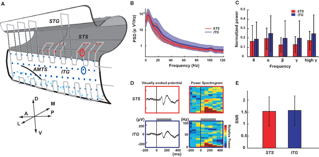
Figure 5. Electrocorticography recording from STS and ITG. (A) Schematic drawing of the left temporal lobe with the electrode array. Dots indicate contacts of the ECoG array covering the STS (red), the lateral part of ITG (blue) and the ventral part of ITG (light blue). Light gray line indicates the outer of the probe. The red and blue circles denote the contact in STS and ITG shown in (D). A, anterior; P, posterior; D, dorsal; V, ventral; L, lateral; M, medial; AMTS, anterior middle temporal sulcus. (B) Power spectral density (PSD) of ECoG signals from the STS (red) and ITG (blue) during the intertrial interval of a visual fixation task. Solid lines and colored areas indicate mean and standard deviation of PSD, respectively. Data from all the STS (n = 16) and ITG (n = 82) electrodes in one monkey are included. (C) Normalized power of ECoG signals from STS (n = 34) and ITG (n = 176) for different frequency bands (θ, 4–6 Hz; α, 8–12 Hz; β, 16–28 Hz; γ, 32–64 Hz; high γ, 68–100 Hz). Data are normalized per band by the maximum power of all electrodes in two individual monkeys. Error bars indicate standard deviation across the contacts. (D) Left: Visually evoked potentials (VEPs) recorded from STS (upper) and ITG (lower). The recording sites are denoted with red (STS) and blue (ITG) circles in (A). A visual stimulus (photograph of a snake) was presented for 300 ms (gray bar). Right: The event-related spectrogram of the VEPs (color-coded from −0.4 to +0.4 dB). All responses were averaged for 20 trials. (E) Signal-to-noise ratio in STS (n = 34) and ITG (n = 176) from two individual monkeys. Error bars indicate standard deviation.
One animal was perfused with paraformaldehyde 4 weeks after surgery. As intended, the flexible probe approached the bottom of the STS at one end, and fitted well to the gyral surface of the ITG at the other end (Figure 6A). Close examination of the hematoxylin and eosin stained coronal sections revealed no evidence of microbleeding or physical damage in the implanted regions compared to the control regions (Figure 6B).
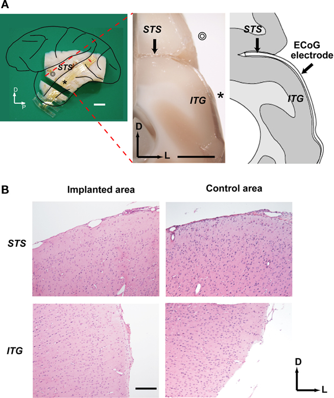
Figure 6. Histological investigation of the ECoG electrode implant. (A) Left: Lateral view of the left hemisphere indicating the position of the coronal section shown in the middle. ⊚ and * denote STG and ITG, respectively. Middle: Coronal cross-section of the brain showing electrode implantation. Right: Line drawing of cross-section. Scale bars indicate 5 mm. P, posterior; D, dorsal; L, lateral; STS, superior temporal sulcus; ITG, inferior temporal gyrus; (B) Microscopic view of the coronal sections. The sections from the implanted area of the STS (upper left) and ITG (lower left) as well as the adjacent unimplanted area were stained with hematoxylin and eosin. A scale bar indicates 300 μm.
Intrasulcal ECoG Stimulation
We inserted a silicone-coated electrode array into the CS of the monkey. We examined thresholds of intrasulcal M1 stimulation for eliciting individual finger, lip, or wrist movements in comparison with stimulation applied to the gyral surface of M1 (Figure 7A). As shown in Figure 7B, thresholds with intrasulcal electrical stimulation (1.0 ± 0.2 mA; mean ± SD, n = 43) were significantly lower than those with gyral stimulation (3.6 ± 0.4, n = 50; p < 0.001, t-test).
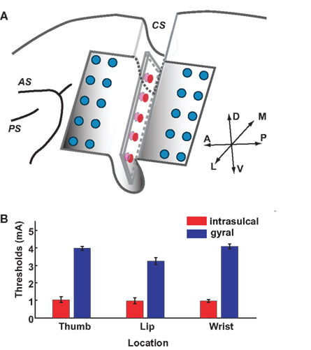
Figure 7. Stimulation thresholds in intrasulcal and gyral M1. (A) Schema of the left frontal lobe with the electrode array. Ten-channel array electrodes (red, five channels in one side) placed between banks of CS were used for intrasulcal cortical stimulation. Ten-channel array electrodes of 20-channel probe (blue) covering precentral gyrus were used for the surface cortical stimulation; AS, arcuate sulcus; PS, principal sulcus; CS, central sulcus. (B) Stimulation thresholds of the intrasulcal (red) and gyral (blue) electrodes for motor responses. Bars show the standard deviations.
Discussion
In the present study, we established minimally invasive neurosurgical protocols to place the custom-designed flexible ECoG probe into the cerebral sulcus of the macaque monkey except for the sites where bridging veins were massively growing. To our knowledge, no previous studies have presented data regarding intrasulcal ECoG recording or stimulation in macaque monkeys. Our approach provides an alternative to blind penetration of metal electrodes to the intrasulcal regions, which often cause hemorrhage or secondary epilepsy. It is becoming clear in the neuroprosthetic literature that the use of microelectrodes for the recording of single cell signals that drive artificial effectors has some problems (Polikov et al., 2005; Chao et al., 2010). The main one is the loss of neural signal after long period of time due to the isolation of the electrode’s tip by glial cells. The present paper shows a new method that could be a good alternative for neuroprosthetics. In the current study, preservation of normal cortical functions of the implanted region was suggested by (1) equivalent quality of the intrasulcal and the gyral ECoG signals in the temporal cortex and (2) lower stimulation thresholds for intrasulcal M1 stimulation compared to gyral M1 stimulation. Histological examination following perfusion also confirmed minimal damage, if any, due to neurosurgery. Based on our results, we propose that microsurgical protocols, cutting-edge neurosurgical apparatus, and ultra-thin electrode arrays are three key factors critical for avoiding the possible risks of subarachnoid surgery such as ischemia or communicating hydrocephalus, as described in detail in the following three sections.
Microsurgical Protocols
Compliance with three microsurgical disciplines was essential (Yaargil, 1984–1996). First, we cut the arachnoid trabecular walls or connective tissues sharply. Blunt dissection is not appropriate for this procedure, because it inevitably causes unnecessary tension damaging the pia mater and the underlying neural tissue. Furthermore, we always placed surgical cotton between the pial surface and surgical devices to preserve the cortical surface. Meticulous care must be taken not to directly touch or compress the cortex. Second, during arachnoid dissection, we withdrew the encountered vessels to the correct bank of the sulcus to which they belonged to. The true boundary of both sides was so complicated that ascertainment of the correct plane was required for opening the sulcus widely. These techniques resulted in preserving all of the vessels including the capillaries. Third, we retracted the cortex with biceps or suction tube only transiently, and never used a brain retractor. Though a retractor can certainly be useful in human brain surgery, in the macaque brain it is difficult to control the position and strength of the retractor in the tiny cerebral sulci. By not using a retractor in the current method, we reduce the risk of local cerebral ischemia that could be caused by long-term retraction. Taken together, these microsurgical protocols are indispensable to preserving the small capillaries and bridging veins, and to maintaining the operative field watery clear.
Cutting-Edge Neurosurgical Apparatus
We introduced two cutting-edge apparatus from human neurosurgery in the present macaque experiments. First, instead of the conventional Horsley–Clarke stereotaxic frame, we developed a three-point free-angle cranial fixation device custom-downsized for the small skull of the macaque in the STS surgery. Without the high flexibility in head positioning, it would be difficult to have direct access to the inferior temporal cortex. In addition, head position was maintained higher than the heart to prevent an increase in intracranial pressure. Although the three-point fixation system could not directly inform the stereotaxic coordinates, a navigation system combining the output of a three-dimensional pointing device onto the structural MRI could enable acquisition of the specific coordinates of the brain during the surgery. Second, we applied a perforator and a craniotome for cranial opening. As in human neurosurgery, the perforator stopped infallibly at the epidural space in macaques, whose skulls are much thinner compared to human skulls. The cortical surface was protected against unintended damage by the tip of craniotome. Compared to the conventional methods of grinding down the skull with a drill in a piecemeal fashion, these apparatus used in our method drastically improved the safety and shortened the time required, so that the cranium can be removed within 1 min. These cutting-edge neurosurgical apparatus are sufficiently versatile for use in various animal model experiments.
Ultra-Thin Flexible Electrode
We devised an optimal electrode array for each experiment. For the ECoG recording experiment, we developed an ultra-thin microelectrode array that would not compress the cortex or cause mass effects. The two-sided comb-like structure of the probe might also add flexibility in fitting to the cortical curvature. Our data clearly demonstrated the feasibility of this probe for intrasulcal recording in macaques. This kind of flexible electrode array is expected to become a ubiquitous tool in system neurosciences, because (1) it enables global cortical mapping with high temporal resolution and minimal invasiveness, (2) signal stability is comparable or superior to existing methods (Chao et al., 2010; Toda et al., 2011), and (3) parameters such as the number, size, shape, and intervals of the electrode array can be flexibly adjusted with micrometer resolution for any experimental purpose. In the cortical stimulation experiment in the current study, we modified a clinical-use ECoG probe to reduce its size by half. Although our ultra-thin probe is not suitable for the purpose of electric stimulation at present, we aim to overcome this problem in the near future.
Toward Whole-Brain Recording and Stimulation
The results of the present recording experiments demonstrated that reliable ECoG signals can be obtained from the intrasulcal cortex, comparable to signals in the adjacent gyral cortex. We employed a simple visual fixation task to evaluate the feasibility of intrasulcal recording in the current protocol. More specific experimental designs to probe higher cognitive functions and detailed analyses in future studies could elucidate the fundamental functional properties of neurons within the sulci. Our stimulation experiment suggested that intrasulcal ECoG could enable us to manipulate the sulcal neural activity in situ more precisely and directly compared to remote surface stimulation. Furthermore, the current protocols are basically applicable to other cerebral sulci of the macaque such as the intraparietal sulcus or the arcuate sulcus (unpublished data).
Given that half of the cerebral cortex of the macaque monkey is buried in cerebral sulci, the development of methods for the intrasulcal recording and stimulation is imperative for advancing our understanding of global brain functions (Hackett et al., 2005). Although ECoG is recognized as a well-balanced candidate, the method had been previously applied only to the gyral cortex due to the lack of appropriate non-invasive protocols for the sulcus. The presently proposed technique expands the applicable scope of ECoG to the intrasulcal regions, the other half of the macaque cerebral cortex, and thus provides a way to directly measure and manipulate the activity of the whole brain.
Conflict of Interest Statement
The authors declare that the research was conducted in the absence of any commercial or financial relationships that could be construed as a potential conflict of interest.
Acknowledgments
We thank N. Kotake, N. Fujisawa for collaboration in the early phase of the study, A. Honda, M. Takayanagi, A. Kawai, Y. Okawa, K. Abe for technical assistance, and M. Yokoyama, Y. Miyashita for encouragement. This work was supported by VLSI Design and Education Center (VDEC) of The University of Tokyo. The Japanese monkeys used in this research were provided by NBRP “Japanese Monkeys” through the National BioResource Project of the MEXT Japan. This work was supported by Strategic Research Program for Brain Science from the MEXT (Isao Hasegawa, Takafumi Suzuki), 2008 Specified Research grant from Takeda Science Foundation, Toray Science and Technology Grant of Toray Science Foundation (Isao Hasegawa), Grant for Promotion of Niigata University Research Project (Isao Hasegawa), Grant-in-Aid for Scientific Research (C) (Isao Hasegawa), Grant (A) from Hayao Nakayama Foundation for Science and Technology and Culture (Isao Hasegawa), grants from Brain Science Foundation (Isao Hasegawa), and Yujin Memorial Grant of Niigata University (Isao Hasegawa).
Supplementary Material
The Movie 1 for this article can be found online at http://www.frontiersin.org/Systems_Neuroscience/10.3389/fnsys.2011.00034/abstract
Movie S1|This movie shows an example of the STS operation as described in the text. Craniotomy: Burr holes were opened by a perforator with an attachment for infants (time from 00:00–00:14). The bone and the dura matter were separated using an elevator, the skull then was cut with a craniotome (00:15–00:57). Microsurgery: The surface arachnoid membrane was initially cut near the blood vessel by a 27-gage injection needle. Sharp dissection was made to open the sulcus using microscissors (01:15–01:39). Electrode array was inserted into the sulcus, confirming that the probe had not been bent (01:40–02:06).
Footnotes
References
Beauchamp, M. S., Lee, K. E., Argall, B. D., and Martin, A. (2004). Integration of auditory and visual information about objects in superior temporal sulcus. Neuron 41, 809–823.
Buschman, T. J., and Miller, E. K. (2007). Top-down versus bottom-up control of attention in the prefrontal and posterior parietal cortices. Science 315, 1860–1862.
Chao, Z. C., Nagasaka, Y., and Fujii, N. (2010). Long-term asynchronous decoding of arm motion using electrocorticographic signals in monkeys. Front. Neuroengineering 3:3. doi: 10.3389/fneng.2010.00003
Felleman, D. J., and Van Essen, D. C. (1991). Distributed hierarchical processing in the primate cerebral cortex. Cereb. Cortex 1, 1–47.
Fisch, L., Privman, E., Ramot, M., Harel, M., Nir, Y., Kipervasser, S., Andelman, F., Neufeld, M. Y., Kramer, U., Fried, I., and Malach, R. (2009). Neural “ignition”: enhanced activation linked to perceptual awareness in human ventral stream visual cortex. Neuron 64, 562–574.
Hackett, T. A., Karmos, G., Schroeder, C. E., Ulbert, I., Sterbing-D’Angelo, S. J., D’Angelo, W. R., Kajikawa, Y., Blumell, S., and De La Mothe, L. (2005). Neurosurgical access to cortical areas in the lateral fissure of primates. J. Neurosci. Methods 141, 103–113.
Hatsopoulos, N. G., and Donoghue, J. P. (2009). The science of neural interface systems. Annu. Rev. Neurosci. 32, 249–266.
Koyama, M., Hasegawa, I., Osada, T., Adachi, Y., Nakahara, K., and Miyashita, Y. (2004). Functional magnetic resonance imaging of macaque monkeys performing visually guided saccade tasks: comparison of cortical eye fields with humans. Neuron 41, 795–807.
Leuthardt, E. C., Miller, K. J., Schalk, G., Rao, R. P., and Ojemann, J. G. (2006). Electrocorticography-based brain computer interface – the Seattle experience. IEEE Trans. Neural Syst. Rehabil. Eng. 14, 194–198.
Liu, H., Agam, Y., Madsen, J. R., and Kreiman, G. (2009). Timing, timing, timing: fast decoding of object information from intracranial field potentials in human visual cortex. Neuron 62, 281–290.
Miller, K. J., Sorensen, L. B., Ojemann, J. G., and Den Nijs, M. (2009). Power-law scaling in the brain surface electric potential. PLoS Comput. Biol. 5, e1000609. doi: 10.1371/journal.pcbi.1000609
Mountcastle, V. B. (1957). Modality and topographic properties of single neurons of cat’s somatic sensory cortex. J. Neurophysiol. 20, 408–434.
Polikov, V. S., Tresco, P. A., and Reichert, W. M. (2005). Response of brain tissue to chronically implanted neural electrodes. J. Neurosci. Methods 148, 1–18.
Rubehn, B., Bosman, C., Oostenveld, R., Fries, P., and Stieglitz, T. (2009). A MEMS-based flexible multichannel ECoG-electrode array. J. Neural Eng. 6, 036003.
Slutzky, M. W., Jordan, L. R., Krieg, T., Chen, M., Mogul, D. J., and Miller, L. E. (2010). Optimal spacing of surface electrode arrays for brain–machine interface applications. J. Neural Eng. 7, 26004.
Toda, H., Suzuki, T., Sawahata, H., Majima, K., Kamitani, Y., and Hasegawa, I. (2011). Simultaneous recording of ECoG and intracortical neuronal activity using a flexible multichannel electrode-mesh in visual cortex. Neuroimage 54, 203–212.
Tomita, H., Ohbayashi, M., Nakahara, K., Hasegawa, I., and Miyashita, Y. (1999). Top-down signal from prefrontal cortex in executive control of memory retrieval. Nature 401, 699–703.
Tsao, D. Y., Freiwald, W. A., Knutsen, T. A., Mandeville, J. B., and Tootell, R. B. (2003). Faces and objects in macaque cerebral cortex. Nat. Neurosci. 6, 989–995.
Keywords: electrocorticography, sulcus, intrasulcal, monkey, MEMS, neurosurgery
Citation: Matsuo T, Kawasaki K, Osada T, Sawahata H, Suzuki T, Shibata M, Miyakawa N, Nakahara K, Iijima A, Sato N, Kawai K, Saito N and Hasegawa I (2011) Intrasulcal electrocorticography in macaque monkeys with minimally invasive neurosurgical protocols. Front. Syst. Neurosci. 5:34. doi: 10.3389/fnsys.2011.00034
Received: 19 April 2011;
Accepted: 12 May 2011;
Published online: 25 May 2011.
Edited by:
Raphael Pinaud, University of Oklahoma Health Sciences Center, USAReviewed by:
Hugo Merchant, Universidad Nacional Autónoma de México, MexicoTakashi Yamamoto, Osaka University Graduate School of Dentistry, Japan
Copyright: © 2011 Matsuo, Kawasaki, Osada, Sawahata, Suzuki, Shibata, Miyakawa, Nakahara, Iijima, Sato, Kawai, Saito and Hasegawa. This is an open-access article subject to a non-exclusive license between the authors and Frontiers Media SA, which permits use, distribution and reproduction in other forums, provided the original authors and source are credited and other Frontiers conditions are complied with.
*Correspondence: Isao Hasegawa and Keisuke Kawasaki, Department of Physiology, Niigata University School of Medicine, Asahimachi Street 1-757, Chuo-ku, Niigata 951-8510, Japan. e-mail: ihasegawa-nsu@umin.ac.jp; kkwasaki@med.niigata-u.ac.jp