Mechanisms of the Flying Chain Fountain
 Eirik G. Flekkøy
 Marcel Moura
 Knut J. Måløy
- PoreLab, Department of Physics, Njord Center, University of Oslo, Oslo, Norway
When a chain is released by one end from a container, it forms a striking arch extending well above the container. This phenomenon is caused by the famous Mould effect and is explained by an anomalous supply of momentum from the container, causing an upwards kick. Using simulations, experiments as well as theoretical arguments we explore the underlying mechanism for this momentum transfer and find that it depends subtly on the nature of the chain as well as on the container. Generally, it does not suffice to assume a model of the chain as a sequence of rigid elements that, due to angular moment conservation, kicks off from the container. Rather the structure of the underlying system must be included, and we analyze how this structure along with the chain mechanics may cause the required upwards force.
1. Introduction
Dynamic ropes and chains in various forms are everywhere, both in daily life, biological systems and technology. Our tenants, the DNA molecule, the tail of a cat, the line of a fly-caster, a whip, or the chain of a falling anchor are but a few examples. Galileo explored hanging chains [1] and later these were shown to be catenaries by Huygens, Leibniz and John Bernoulli. However, the fact that the equations governing hanging and moving chains have been around for almost 400 years [1–3] does not rule out the possibility that even the simplest systems may still exhibit surprising behavior [4–6].
Recently, Mould [7] observed that when the end of a chain is dropped from a pile contained at some height above the floor, gravity will set it in motion, and eventually the whole chain will have flowed over the edge of the container. This is no surprise. What is a surprise, and what has caused more than 3 million views on YouTube, is the fact that the chain forms a rising, self-supporting arch that extends a significant height above its container, as is illustrated by the simulation of Figure 1. Since physics should also be fun to a general audience, a discussion of such a phenomenon is of real importance.
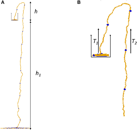
Figure 1. (A) A snapshot from a simulation of the chain fountain with (B) a closeup. The tensions T1 = T2 are at the same height. Larger blue beads are introduced for visualization purposes only and have the same properties as the other beads.
Careful analysis of the process first carried out by Biggins [4] and Biggins and Warner [5], has shown that this arch formation depends on the existence of an upwards acting force that literally pushes the chain out of the container. They observed that the origin of this force is the key to understanding the phenomenon. It was explained by modeling the links of the chain as rigid segments that provided a kick against the underlying packing as they where lifted from it. This kick-off effect relies on the assumption that, due to the limited flexibility of the chain, it actually behaves as a sequence of rigid elements, and that these rotate sufficiently abruptly around their centers of mass to provide the kick. This effect has also been taken as the underlying mechanism for the fountain by other authors [8].
In the present letter we show how simulations including the proposed kick-off effect as the only active mechanism, fail to produce a chain fountain. Only when a model of a bumpy underlying packing is included, do the simulations produce a fountain, and this fountain survives when the rigidity of the links is removed in favor of a completely flexible bead chain, which cannot support the kick-off effect. The difference between these two chains is the existence of a maximum bending angle between the links that connect the beads.
2. Materials and Methods
In order to explore the reasons for the fountain it is necessary to express the momentum balance of the chain. Such descriptions exists in several text books, such as that on chain dynamics and shape [9] and the necessary equations of motion have been worked out in great detail [10, 11], at least for the steady state situations.
Following Briggs and Warner we shall assume such a steady state where the chain with mass per unit length λ moves with a constant shape at velocity v. The distance along the chain from the first bead at the bottom of the container, to the last is measured by the coordinate s. Then the tension T along the chain at time t may be written T(s, t) = T(s, t)et, where et is the unit tangent vector. In steady state there is a balance between gravity g and the tension so that
Taking the tangential component yields , which may be integrated along the chain to give
where Δh is the height difference between the end points. This means in particular that T1 = T2, shown in Figure 1 since these tensions are measured at equal heights.
We now introduce the net upwards force on all the beads inside the container
where G is gravity and Fz the force from the container bottom or other beads. For the part of the chain still at rest this force Fz keeps the chain from falling through the bottom of the container. Clearly, the net force may be written as a sum over the corresponding forces on individual beads, where Δfi is the vertical net force on bead i. For beads at rest, there will be a local balance between the gravity on a chain segment and the force supporting it and Δfi = 0. But for beads that are set into motion and collide with other beads Δfi ≥ 0. Now, assuming the beads leave the container vertically at a velocity v they acquire a momentum ΔP = δmv = λdsv = λv2dt, which is provided by the total force on the container beads, that is
On the downward moving side of the chain, there must be a force balance between gravity and tension, so that
where TF is the tension at the floor. It has been observed- at least for different types of chains- that the interaction between the falling chain and the floor may produce an added downwards force, causing freely falling chains to accellerate slightly faster than gravity [10]. However, for the sake of simplicity, we shall in the following neglect this interesting effect and assume that TF = 0. This implies that the effective position of the floor is slightly different from the real floor, thus producing a small correction to h1.
Using the same momentum argument as for the pick-up force we then find that the upwards force from the floor on the falling chain is simply λv2. The steady state assumption means that the total momentum of the entire chain is unchanged, and for this reason the downwards forces acting on it must balance the upwards forces. The former is the gravity that acts on the chain that has left the container, and the latter the floor and container forces, that is
By eliminating T1 = T2 from Equations (4) and (5) we get , which when inserted in Equation (6) gives the following expression for the fountain height
In other words, the weight of the upwards moving part of the fountain is balanced by the net container force.
Equation (7) was in fact derived by Biggins and Warner [5], albeit with an interpretation of ΔFz based on the kick-off mechanism. Note that ΔFz may derive from any part of the chain that is in motion, that is, upwards momentum may be accumulated by a whole segment of the chain that is about to take off.
2.1. Experiments
In order to to determine how the momentum transfer takes place, experiments with a chain similar, or equal, to the one used by Biggins and Warner are needed to look at the details of the take-off process. They were carried out in the following way: First, the way the chain is stacked in the container is crucial in order to avoid entanglement. Initially, a circular, spiral packing was attempted, but that turned out to lead to entanglement. A more successful routine consists in piling up the chain at a given location by the wall in the container, and then, after the pile has grown large enough that its base is reaching the middle of the container, we move to the opposite side of the container and repeat the procedure. The third location is at the wall midway between the two first ones, and the fourth and final location opposite to the third one. After that, we move again to the first location and go on like this until the whole chain fits inside the container.
Images were acquired with a Nikon J4 High-res camera is used to obtain images of the whole chain and is placed on a high tripod about 3 m away from the system, whereas high resolution images were acquired at a temporal rate of 60 frames per second. In Figure 2 it is seen that a typical moving chain segment extends over a significant part of the container, thus accumulating momentum over a series of collisions with the underlying chain. We did not observe a frequent occurrence of large bending angles, but often a formation of a stationary spiral hitting the underlying packing at its bottom could be observed. It would thus seem that the necessary momentum transfer happens more in the way of a bumpy take-off than by the kick-off mechanism.
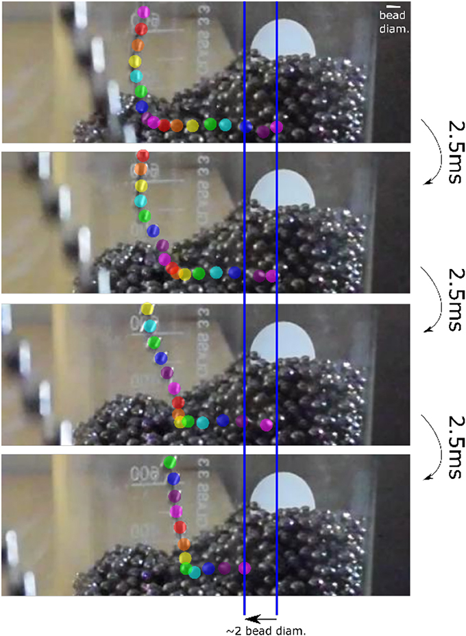
Figure 2. A time sequence of 7.5 ms using a 50 m chain of 4.5 mm beads. Individual chain beads are traced by different colors.
2.2. Simulation Method
To gain further insight in the momentum transfer process, the following simulation method was used. They essentially integrate Newtons 2. law for the individual beads of the chain using a Velocity-Verlet scheme of 4th order accuracy in time. The beads are taken to interact through a harmonic potential with an equilibrium separation a0, i.e., if the separation between two neighboring beads is Δr = r1−r2 then . Also, we employ an interbead dissipative force −βΔv, where Δv is the relative velocity between neighboring beads. This force dampens longitudinal fluctuations, which is certainly realistic. However, no corresponding angular friction is included, which means that transverse waves may tend to die out more slowly than in the experiments. The container is implemented both by conservative and dissipative forces: The side walls and top rim of the container is implemented by a conservative potential like that of of the interbead potential, but with a force that always pushes the bead away from the walls and top rim. At the bottom, however, a horizontal dissipative force, or sliding friction, −βcv∥, where v∥ is the horizontal velocity component, is included. This force dampens the motion inside the container that would otherwise remain for a long time. Each bead interacts only with its two nearest neighbors, so to model the underlying bead packing the bottom of the container is equipped with bumps: The perturbation asin(2π(x+y)/a0), where a is an amplitude, x and y are the horizontal coordinates, is added to the local height of the container bottom. In this way beads on the bottom will encounter bumps at a separation equal to the bead diameter. The distance b between the bead center and the bottom at which the interaction sets in, is normally equal to half the interbead distance, i.e., b = a0/2, but may also be taken to be smaller, thus simulating smaller beads.
The chain is kept from bending more than the maximum bending angle Θmax by the introduction of an internal force FS, that counteracts the bending once this angle is exceeded. It may be considered two internal pairwise interactions, each with a force ±FS/2 between two nearest neighbors. The value of Θmax = 63° is the value of the chain used in the experiments and apparently also the value in the chain used by Biggins and Warner.
The internal stiffness force, which is illustrated in Figure 3 only kicks in when the angle Θ between the unit vecors along th elinks, e2 and e1, exceeds a maximum value Θmax. This force takes the form
and is applied to every ball. If Θmax is zero this would result in a long rigid chain, so we choose it in stead to the measured value Θmax = 63°. It is possible to use this force to simulate a piecewise rigid chain by setting Θmax = 0 for ever third bead, and Θmax = π in between, as is illustrated in Figure 4. As experiments with the piecewise rigid chain may be carried out using pieces of pasta, the corresponding model used in the simulations will henceforth be termed the pasta model. The floor, which is located at z = 0 is implemented by a adding a strong vertical damping in the form of another frictional force −βFvz.
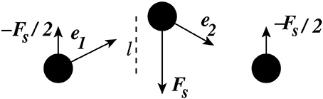
Figure 3. The force FS implementing the stiffness interactions.
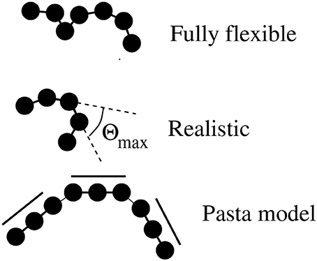
Figure 4. The various simulated chains with differing internal stiffness interactions. The chain used in the experiments has Θmax = 63°.
3. Results
By setting Θmax = 63°, we model the realistic chain, but by setting Θmax = 180° a fully flexible chain with no support for the kick-off mechanism is modeled. Simulations of these chains show two key features: First ΔFz is non-zero for both chains, and, second, they indicate that the time averaged force Δfi is largely non-zero only for the last bead to interact with the bottom. This is shown in Figure 5 where i = 1 labels the last bead to interact with the undulating container bottom and i > 1 labels beads that have not yet taken off. Although the main momentum transfer happens on the last bead, Figure 5 still shows a gradual decay of the net force up to around i = 10. So, the fountain-producing force is positive for both the realistic chain and the flexible chain that has no bending rigidity and thus no possibility to support the kick-off mechanism.
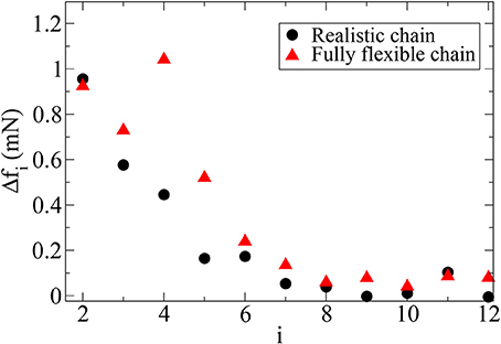
Figure 5. The time-averaged force Δfi from the container on the realistic and flexible chain as a function of bead number. Here i = 1 labels the last bead to interact with the bottom, i = 2 labels the second last bead to interact with the bottom etc. The i = 1, values are Δf1 = 64 and 72 mN for the flexible and realistic chains respectively and are way outside the range of the i ≥ 2 values which are shown for here.
The simplest possible model for the ΔFz-force is based on the idea of collisions between the beads that are accelerated along the bottom as they are lifted off, and the beads that are still stationary. The ΔFz-force may be calculated as the added upwards momentum from the collisions per unit time. This quantity is thus proportional both to the frequency of the impacts and the momentum added by each impact. The impacts will happen at a rate ∝v, and it is reasonable to assume that each impact will contribute a momentum which is also proportional to v. Therefore we may write , where we have introduced a constant of proportionality α, which was also used by Biggins and Warner. They derived the same dependence on the basis of their kick-off mechanism. Now, using Equations (4) and (5) to obtain and inserting this result in Equation (7) gives
a prediction which is the same for the both the bumpy take-off and the kick-off mechanisms. For this reason, the simplest experiment– measuring h as a function of h1– is eliminated as the crucial one for distinguishing between the two mechanisms.
Using the realistic chain the fountain show in Figure 1 is produced. Figure 6 shows how the corresponding fountain height h evolves with time, both in the simulations and the experiment. In the figure we have also included a semi-analytic theoretical predictions made by Biggins and based simply on momentum balance in various parts of the chain. This theory [4] implies that the only relevant time scale for the relaxation of h(t) is , a result which appears well justified. Using α = 0.12 to fit the theory to the experiments good agreement in terms of the predicted and measured heights are observed. The fact that the early time experimental values are above the theory is explained by the finite height of the container, which are absent in the theory. Simulations lack any dissipation associated with beads colliding with the rim of the container and therefore produces a slightly larger h.
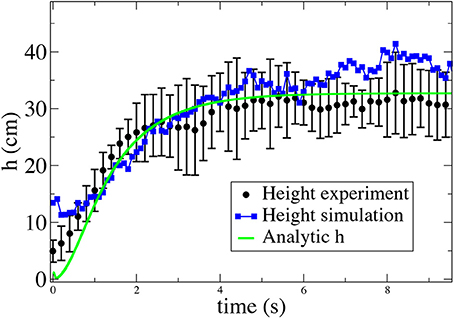
Figure 6. The fountain height obtained from an average of 8 experiments and a simulation with h1 = 2.4 m along with a semi-analytic prediction derived from Equations (11) and (12) in Biggins [4] using α = 0.12.
Observing that a bumpy packing, or container bottom, is crucial to produce a fountain both for the realistic and fully flexible chain, we may still inquire if there are any other chains that do not rely on the structure of the bottom. Indeed, Biggins [4] explored two additional chains, one that was composed of piecewise rigid segments, thus corresponding more closely to his theoretical model, and one with well separated beads, which could not support the kick-off effect. The results were that the first chain did produce a fountain, and the latter not.
However, doing the same in our simulations, using (i) a fully flexible separated bead chain (with a0 = 3 cm and b = a = 3 mm) running over the normal rough bottom (a = a0/4), and (ii) the pasta model with a perfectly smooth container bottom, we observe a fountain in both cases. The results are illustrated in Figure 7.
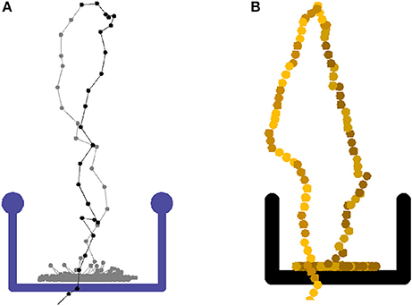
Figure 7. (A) Snapshot from a simulation of the chain fountain with separated beads and (B) the pasta model. The latter is designed to optimize the kick-off effect. Both simulations correspond to the experiment done by Biggins [4].
In Figure 8 we collect the results of all the different chain models measuring h as a function of h1. They are carried out by simulating the different chain and container models. We have also include the original measurements of Biggins and Warner [5]. Our realistic simulations using a bottom roughness a = a0/4 agree well with these. We have truncated the measurements at h1 = 4 m as the chain lengths which have been applied, do not allow the system to reach a steady state above that container height. This may be understood from the fact that both th and the asymptotic velocity grow as .
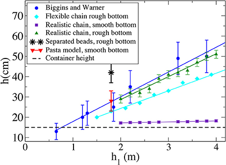
Figure 8. The fountain height as a function of elevation h1 for the different models.
4. Discussion
It is seen that the combination of a realistic chain and a smooth bottom produces no fountain, thus ruling out the kick-off mechanism as a complete explanation for the phenomenon. The kick-off mechanism by itself only works to explain the chain fountain of the pasta model. However, it is seen that while both the realistic and flexible chains rely on a rough bottom to produce a fountain, the existence of a realistic rigidity enhances the fountain. Part of this enhancement could have the rather trivial explanation that a more flexible chain will allow more buckling thus increasing the chain mass contained in the height h, or, effectively the mass density λ. This would tend to reduce h for a given ΔFz. However, a priori, it would seem likely that an upwards collision force on bead i = 1 would cause a downwards motion on the i = 2 bead via the stiffness force FS thus re-introducing the kick-off effect (the effect of FS's is to ensure conservation of angular moment). However, in Figure 5 no increase of Δf2 is observed from the introduction of a realistic stiffness. So, this does not appear to be the explanation.
Coincidentally, perhaps the pasta model agrees well with the realistic chain on a rough bottom. On the other hand, the separated-beads model, initially thought to produce no fountain at all, makes a higher fountain than all the other models at a given h1. This is perhaps best understood as a lack of screening effect: When the bead separation is increased, the upwards motion of a colliding bead that is needed to produce a given lift on the bead behind, is also increased. This means that the bead behind is more likely to pick up vertical momentum through a second collision. The lack of a fountain in the experiments may well be caused by dissipation in the collisions between the beads and the rim of the container.
To summarize, and to answer our initial question “what are the mechanisms requires to produce a chain fountain?” Figure 9 represents a kind of boolean phase diagram giving the crude yes or no's. There are still a number of open, intriguing questions that remain, however. Since the existence of a positive ΔFz causes a reduction in the dissipation associated with the picking up of a chain, it is of some general-, and even technological interest to understand how it may be optimized by changing the many parameters that describe the chain.
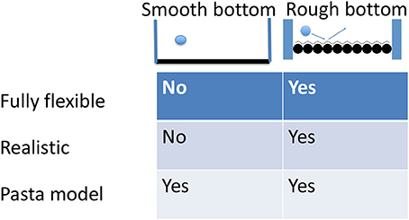
Figure 9. Phase diagram for the different simulation conditions and whether they produce a fountain.
Author Contributions
EF did the theory and simulations as well as the main part of the writing. MM did the experiments as well as the written description of those, while KM having developed the labs that made the experiments possible supervised these. All authors contributed to the discussions defining the work.
Funding
We thank the Research Council of Norway through its Centres of Excellence funding scheme, project number 262644.
Conflict of Interest Statement
The authors declare that the research was conducted in the absence of any commercial or financial relationships that could be construed as a potential conflict of interest.
Acknowledgments
We wish to thank Ellen Karoline Henriksen and Carl Anghell who first introduced us to the flying chain, Dragos-Victor Anghel for his valuable theoretical input and Frédéric Lindboe for his practical tips on how to pack the beads.
References
1. Drake S. Two New Sciences. Madison, WI: University of Wisconsin Press (1974). Original work by Galilei G. published in 1638.
4. Biggins J. Growth and shape of a chain fountain. Europhys Lett. (2014) 106:44001. doi: 10.1209/0295-5075/106/44001
5. Biggins J, Warner M. Understanding the chain fountain. Proc R Soc A (2014) 470:20130689. doi: 10.1098/rspa.2013.0689
6. Hanna J, Santangelo C. Slack dynamics on an unfurling string. Phys Rev Lett. (2012) 109:134301. doi: 10.1103/PhysRevLett.109.134301
7. Mould S. Available online at: http://stevemould.com/siphoning-beads/ (2013).
8. Pantaleone J. A quantitative analysis of the chain fountain. Am J Phys. (2017) 85:414. doi: 10.1119/1.4980071
9. Routhe E, Routh EJ. 1860 Dynamics of a System of Rigid Bodies, With Numerous Examples. Cambridge: MacMillan (1860).
Keywords: flying chain, continuum mechanics, ropes and cables, strings, outreach
Citation: Flekkøy EG, Moura M and Måløy KJ (2018) Mechanisms of the Flying Chain Fountain. Front. Phys. 6:84. doi: 10.3389/fphy.2018.00084
Received: 27 April 2018; Accepted: 23 July 2018;
Published: 14 August 2018.
Edited by:
Miguel Rubi, University of Barcelona, SpainReviewed by:
Fernando A. Oliveira, University of Brasília, BrazilIvan Santamaria Holek, Universidad Nacional Autónoma de México, Mexico
Copyright © 2018 Flekkøy, Moura and Måløy. This is an open-access article distributed under the terms of the Creative Commons Attribution License (CC BY). The use, distribution or reproduction in other forums is permitted, provided the original author(s) and the copyright owner(s) are credited and that the original publication in this journal is cited, in accordance with accepted academic practice. No use, distribution or reproduction is permitted which does not comply with these terms.
*Correspondence: Eirik G. Flekkøy, e.g.flekkoy@fys.uio.no