Seismic behavior and design of wall–EDD–frame systems
 Oren Lavan
 David Abecassis
- Faculty of Civil and Environmental Engineering, Technion – Israel Institute of Technology, Haifa, Israel
Walls and frames have different deflection lines and, depending on the seismic mass they support, may often possess different natural periods. In many cases, wall–frame structures present an advantageous behavior. In these structures, the walls and the frames are rigidly connected. Nevertheless, if the walls and the frames were not rigidly connected, an opportunity for an efficient passive control strategy would arise: connecting the two systems by energy dissipation devices (EDDs) to result in wall–EDD–frame systems. This, depending on the parameters of the system, is expected to lead to an efficient energy dissipation mechanism. This paper studies the seismic behavior of wall–EDD–frame systems in the context of retrofitting existing frame structures. The controlling non-dimensional parameters of such systems are first identified. This is followed by a rigorous and extensive parametric study that reveals the pros and cons of the new system versus wall–frame systems. The effects of the controlling parameters on the behavior of the new system are analyzed and discussed. Finally, tools are given for initial design of such retrofitting schemes. These enable both choosing the most appropriate retrofitting alternative and selecting initial values for its parameters.
Introduction
Many of the relatively new buildings located in seismic regions were designed according to stringent seismic codes. These are expected to perform relatively well in seismic events. Contrariwise, many older existing buildings have known deficiencies. These buildings are still expected to be a part of the landscape for many years to come. Seismic retrofitting of such buildings may reduce their probability of collapse as well as the level of damage expected to them in seismic events. This, in turn, may shorten the time required to bring them to normal functionality (Nakashima et al., 2014).
A very efficient and promising approach for seismic retrofitting and damage control makes use of energy dissipation devices (EDDs) [see, e.g., Soong and Dargush (1997), Christopoulos and Filiatrault (2006), and Takewaki (2009)]. Out of those, fluid viscous dampers (FVDs) have been shown to effectively reduce both displacement and force related seismic responses of structures (Constantinou and Symans, 1992; Lavan and Dargush, 2009; Lavan, 2012). Hence, the use of FVDs seems natural for seismic retrofitting where both displacements and forces due to earthquakes are to be decreased. Indeed, optimal design of such dampers for the purpose of seismic retrofitting of frame structures received much attention (Zhang and Soong, 1992; Gluck et al., 1996; Takewaki, 1997; Singh and Moreschi, 2001; Lopez-Garcia and Soong, 2002; Dargush and Sant, 2005; Lavan and Levy, 2005, 2006, 2009, 2010; Aydin et al., 2007; Lavan et al., 2008; Lavan and Dargush, 2009; Adachi et al., 2013; Aguirre et al., 2013; Kanno, 2013; Martínez et al., 2013; Sonmez et al., 2013; Gidaris and Taflanidis, 2014; Hatzigeorgiou and Pnevmatikos, 2014; Lavan and Amir, 2014; Lin et al., 2014; Lavan, 2015). To allow a quick examination of whether such devices are a good alternative, simple methodologies for initial design were proposed as well (FEMA 356, 2000; Palermo et al., 2013; Landi et al., 2014; Rama Raju et al., 2014). Uncertainty in structural and/or ground motion parameters was also evaluated (Lavan and Avishur, 2013; Peng et al., 2014; Tubaldi et al., 2015) or taken into account as part of the design process (Gidaris and Taflanidis, 2014).
When seismic retrofitting of frame structures is the sole concern, the abovementioned research presents a wide arsenal of design tools in the hands of the engineer. Nevertheless, in Israel, seismic retrofitting of old buildings is usually done in parallel to adding shelter rooms to protect the tenants from potential threats from various weapons. These shelter rooms are made of reinforced concrete and their in-plan location in the various stories is consistent so as to form reinforced concrete cores. These new cores are rigidly connected to the existing floors, thus, they supply a new lateral load resisting system (see Figure 1A). This considerably reduces the displacements of the existing structure, hence the internal forces in some existing structural elements. However, the high stiffness of the cores results in a relatively short natural period. Thus, for most ground motion records, i.e., relatively short predominant period ones, much larger seismic inertia forces are attracted. These forces that act on, and are transferred by the existing slabs, are potentially larger than they can take. Furthermore, the path that the inertia forces take from the mass to the new lateral load resisting system is different from before. As the new cores are located at the edges of the building, the path now is much longer. Thus, the slabs need to transfer loads between points that are at a large distance, i.e., the distance between the center of mass and the lateral load resisting elements. This may require strengthening of the existing slabs, which is not practical. In addition, a major portion of the large inertia forces is to be transferred through the connections between the new cores and the existing slabs. As the existing slabs are usually thin and their concrete quality is relatively low, these connections may be problematic. Furthermore, very large horizontal forces are to be carried by the new core system. This may result in large base moments. These grow considerably with the number of stories. As the new cores support gravity loads due to their self-weight only, large moments may lead to considerable tension in their foundations. Depending on the soil type, this may lead to additional considerable expenses. Similarly, the combination of large moments and small compression forces in the cores leads to larger reinforcement ratios. Finally, when it comes to important buildings that are expected to function after the earthquake, the large accelerations expected due to the considerable increase in stiffness is also an issue due to the potential damage they could induce.
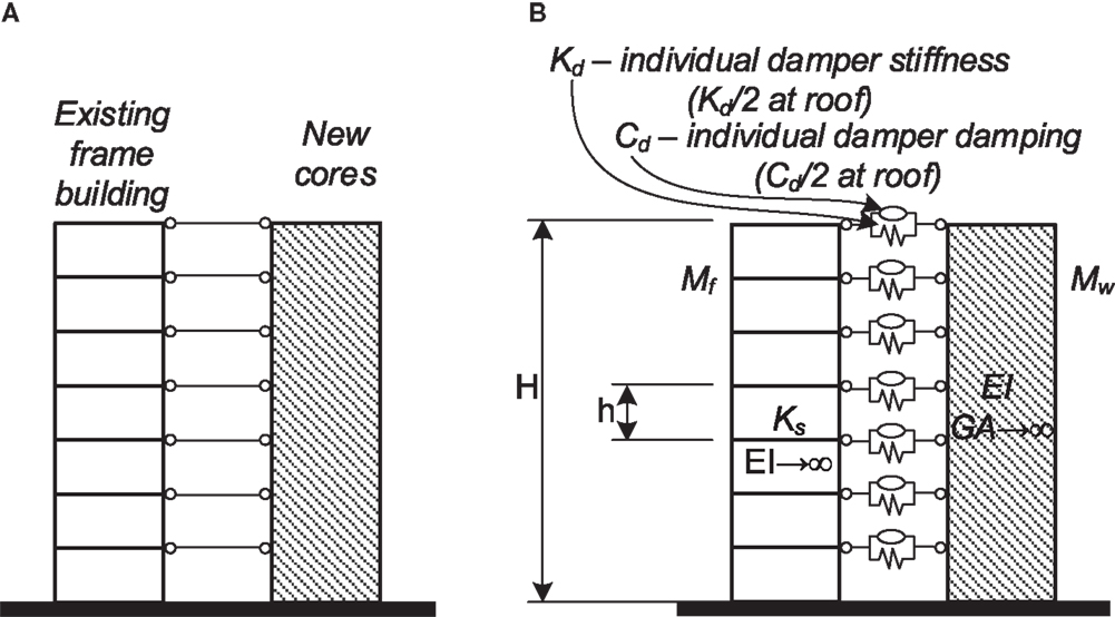
Figure 1. Schematic of rehabilitation system: (A) wall–frame; (B) wall–EDD–frame.
The new cores, as they are rigidly connected to the existing building, considerably increase the inertia forces. Nevertheless, if they were not rigidly connected, their natural period would have been much different from that of the existing building. Furthermore, their deflection line would have been different in nature from that of the frames: the deflection lines of wall structures possess larger drifts at the top stories while those of frame structures possess larger drifts at the bottom stories. This opens an opportunity for an efficient passive control strategy. If the two systems are not rigidly connected (e.g., by using seismic gaps), the relative displacements and velocities between them are expected to be large. Thus, connecting the two systems by EDDs to result in wall–EDD–frame systems (see Figure 1B and the detailed description in Section “Structural Systems”) is expected to lead to an efficient energy dissipation mechanism. This, of course, depends on the parameters of the system (wall and frame stiffnesses; height, distribution of mass between the two systems, etc.) as well as on the parameters of the EDDs used (damping coefficients and stiffness). While the motivation for research on this system stems from the particular environment in Israel, the wall–EDD–frame system and the research presented herein are fully applicable in other cases. It should be noted that a related system, where the walls were assumed infinitely rigid, was proposed and studied by Trombetti and Silvestri (2004, 2006) and Silvestri and Trombetti (2007). They noted that, in their system, a mass-proportional added damping matrix is attained for the frame. This is in contrast to the stiffness-proportional added damping matrix attained when dampers are assigned within the frame stories. They further emphasized the superiority of mass-proportional damping. Another related system was presented by Murase et al. (2013). In this novel structural system, a base isolated frame structure was connected with oil dampers to a free wall. Through frequency domain and time domain analyses, they demonstrated the effectiveness of this structural system for both pulse-type and long period ground motions.
The idea of connecting adjacent structures by controllers to reduce their responses is not new [see Cimellaro and Lopez-Garcia (2011), and references therein]. In the context of using FVDs or viscoelastic dampers (VEDs), Aida et al. (2001) proposed an approximate analysis model for two buildings connected by a VED. The MDOF model of each building was replaced by its first mode representation, thus, resulting in a 2-DOF model for the analysis. They further indicated that VEDs are only efficient if the buildings connected are of different natural periods. In that context, optimum viscous damping values were proposed for a damper connecting two SDOF systems excited by either harmonic or white-noise ground motions (Bhaskararao and Jangid, 2007). Closed-form equations for the frequency response characteristics of two SDOF systems connected by a spring and a dashpot in parallel where derived as well (Richardson et al., 2013). A 2-DOF reduced model was also used by Huang and Zhu (2013) to investigate the optimal design of VEDs connecting adjacent frame buildings. They further proposed a design method for the optimal locations and sizes of the dampers. Sun et al. (2014) derived expressions for stochastic characteristics and responses of a twin-tower structure linked by a sky-bridge. They assumed a white-noise input and a simplified 3-DOF model (one DOF for the mass of the bridge). Subsequently, they investigated the optimal parameters of the connections.
In other research works, a full MDOF system was considered. Enrique Luco and De Barros (1998) investigated the optimal viscous damping connecting two adjacent shear beams of different heights. For that purpose, they derived the continuous equations (in space) assuming uniformly distributed parameters for each of the beams. The optimal parameters of the dampers were found based on frequency response parameters of the taller structure. Zhang and Xu (1999) adopted the complex modal superposition method using a random seismic input. They further identified the optimal parameters of VEDs connecting adjacent frame structures using a parametric study. In another work, they proposed an analysis procedure for adjacent frame structures connected by VEDs while considering a Maxwell model to represent the dampers (Zhang and Xu, 2000). A parametric study on six story frame buildings connected by FVDs was presented by Trombetti and Silvestri (2007). They highlighted the superiority of this arrangement of dampers that leads to mass-proportional damping over an inter-story placing of viscous dampers. A very unique approach was taken by Takewaki (2007). He developed a frequency domain method to evaluate the input seismic energy to a system of two frames connected by viscous dampers. This enabled him to come to a very strong conclusion that the input energy to the system considered is insensitive to the quantity of the dampers and their locations. Thus, the larger the energy absorbed by the dampers, the smaller the energy input to the frames themselves. Patel and Jangid (2010) investigated several damping distributions between two similar frames. They found that viscous dampers are very efficient in such structures and that there is an optimum damping value to minimize the structural responses. Similar observations had been presented by Kim et al. (2006). Cimellaro and Lopez-Garcia (2011) applied, for the design of damping between adjacent buildings, an algorithm that was originally proposed for the design of dampers in frame structures (Gluck et al., 1996) as well as for the damping and weakening of frame structures (Lavan et al., 2008). Recently, Tubaldi (2015) derived the non-dimensional continuous equations of two shear frames of different heights connected by a VED at the top of the shorter frame. Those were then analytically analyzed to lead to the natural periods and modes. An approximate reduced order model and closed-form solutions for the modal parameters were then proposed and compared to the analytical results with good agreement. Another recent research presented by Bigdeli et al. (2015) proposed a bi-level optimization approach for the optimal design of dampers connecting two frame structures. In the first level of optimization, the combinatorial problem of damper placement was solved, while in the second level the continuous design of each damper was handled.
Most of the abovementioned works investigated the response of either SDOF representations of two buildings connected by a single VED or two MDOF frames connected by several VEDs. A main conclusion was that in these cases dampers are expected to efficiently reduce the responses only if the periods of the two SDOF systems, or the two frames, are sufficiently different. It is argued here that if two buildings having different lateral load resisting systems (i.e., frames and walls) are coupled by dampers, a reduction of the responses is expected even if the periods of the buildings are similar. This is due to the differences in their deflection shapes.
Research on frames connected to infinitely rigid walls by dampers has been presented in the literature. Trombetti and Silvestri (2004, 2006) identified the superior effect of mass-proportional damping over stiffness-proportional damping in frame structures. They further proposed various approaches for achieving such damping characteristics by using FVDs. One of the approaches connected horizontal dampers from the floors of the frame to an infinitely rigid wall.
As can be seen, the efficiency of connecting two systems with different periods by means of EDDs has been highlighted many times. This has been investigated using either SDOF representations of two buildings connected by a single VED, two MDOF frames connected by several VEDs or an MDOF frame connected to a rigid wall by several FVDs. The behavior of frame–EDD–wall systems, however, has not been examined while considering the flexibility of the wall. Furthermore, no tools for initial design of such systems are available.
It is the aim of this paper to gain some insight to the seismic behavior of wall–EDD–frame systems as part of retrofitting existing frame structures. This was done by means of a rigorous parametric study. The controlling parameters of such systems were first identified, and their effect on various responses of interest was assessed. Furthermore, the results presented could be used for initial design of such systems in two levels. At the first level, the engineer could assess the feasibility of such a strategy for a given building and its pros and cons compared to rigidly connecting the new walls to the existing building. At the second level, based on the graphs presented herein, the engineer could choose appropriate values for the initial design of the controlling parameters.
Structural Systems Considered and Modeling Assumptions
Structural Systems
The focus of this paper is the behavior and design of wall–EDD–frame systems as part of retrofitting existing frame structures. Such a system is presented in Figure 1B. The system consists of a frame and a wall that are connected by viscous dampers and springs. The seismic mass per floor taken by the frame is Mf, equal for all floors, and the story stiffness of the frame is Ks (shear force required to result in a unit inter-story drift). The seismic mass per floor taken by the wall is Mw and the bending stiffness of the wall is EI. The damping coefficient of each viscous damper is Cd while the stiffness of each spring is Kd. The total height of the N story building is H with a typical story height of h = H/N. For the sake of comparison, a similar system where the frame and the wall are rigidly connected is also considered. This system is presented in Figure 1A. In the models described above a few assumptions are embedded. Those are:
• A plane model is considered, indicating that the parametric study results are applicable to structures where the torsional response is limited.
• A fixed base is assumed for both frame and walls.
• A uniform distribution of structural and damping properties was assumed along the height. While this may not necessarily be the case, in many cases, the use of some average properties may still lead to very good approximations.
• The frame is assumed to behave like a shear beam while the wall is assumed to behave like a flexural beam. That is, in the frame, axial deformations of the columns are neglected while, in the wall, shear deformations are neglected.
• The inherent damping of the frame is considered by a Rayleigh damping matrix constructed for the bare frame with 5% damping in the first and third modes. A similar procedure is used to consider the inherent damping of the wall.
• It is assumed that the behavior of the system could be approximated by use of linear analysis. That is, either the behavior of the system is actually linear, or a linear analysis leads to a good approximation of the displacement related responses. This assumption holds reasonably well for regular structures with either a medium to long period or with low-ductility demands. It should be noted that, when viscous dampers are utilized, the behavior of the system is indeed expected to be linear or close to that. Thus, the ductility demands are expected to be low. Furthermore, in such cases, the fundamental period of the system is similar to that of the bare frame, which is usually long enough.
Seismic Environment
The seismic environment, in this study, is represented using a typical 5% damping pseudo-acceleration response-spectrum. It is assumed that the periods of the systems considered are within the period range of the constant acceleration and constant velocity regions of the spectrum (see, e.g., Figure 2). Thus, two parameters are controlling the shape of the spectrum. In this study, the elastic 5% damping spectral acceleration at some given period (with no behavior factor), Sa(T′), and the corner period, between the constant acceleration and the constant velocity regions, Tc, are adopted. The period at which Sa(T′) is evaluated will be chosen in the next sections.
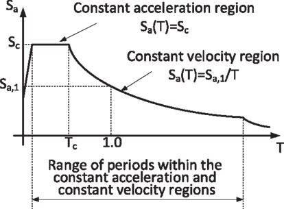
Figure 2. Psuedo-acceleration response spectrum adopted in the study.
Responses of Interest
In this paper, the frame is assumed to be the lateral load resisting system of the existing old building as well as its gravity carrying system. Thus, the maximum peak inter-story drift angle of all stories of the frame, IDf, is of much importance. Here, the inter-story drift angle is the horizontal displacement of the story ceiling relative to the story floor normalized by the story height. Based on this parameter, one could assess if yielding occurs and to what extent. Inter-story drifts also indicate the extent of damage to some non-structural components (e.g., partition walls). Furthermore, the maximum peak elastic shear in the frame could be computed by GA⋅IDf where GA is the smeared frame stiffness as will be explained in section “Controlling Parameters”. Another important response related to the frame is its base over-turning moment, OTMf, that affects the axial forces in its columns and its foundations. Recently, focus was also drawn to the level of absolute accelerations. These are especially important in cases where the structure is expected to remain operational after the seismic event. As most of the important functions in the considered buildings are expected to be supported by the frame, the maximum peak frame absolute acceleration, Af, is considered as a response of interest.
The walls are the new lateral load resisting system. In general, no partition walls or gravity frames are rigidly connected to these walls; hence, their inter-story drifts are of no particular importance. The design of these walls and the design of their foundations are dictated by the wall base shear, BSw, and base moment, OTMw. Thus, these are the responses of interest related to the walls.
Finally, the responses of interest related to the connection between the frame and the wall, and to the EDDs are identified. Viscous dampers and springs are designed and sized based on the peak force they are expected to experience, Fd. Furthermore, this force is to be locally taken by the existing slabs at the region of the connection. Thus, the connection force serves as the first response of interest related to the connection. To avoid pounding between the frame and the wall, it is important to insert seismic gaps. Furthermore, another design parameter of EDDs is the stroke they are expected to experience. Thus, the second response parameter related to the EDDs is the maximum peak relative displacement between the frame and the wall, or the damper elongation/contraction, Dd.
The Parametric Study Design
Controlling Parameters
In view of the previous section, the parameters controlling the behavior of the problem are Mf, KS, Mw, EI, H, h, Cd, Kd, Sa(T′), and Tc. For the sake of generality, “smeared” properties per unit height will be used as parameters rather than discrete properties. It is assumed that two systems with similar smeared properties but with different numbers of stories will have similar smeared responses. The error associated with this approximation is also assessed later on in Section “Analysis Approach.” The use of smeared properties to transfer from discrete models to continuous ones is not new and has even been used in the seismic analysis of structures with EDDs (Lavan, 2012; Tubaldi, 2015). It is known to lead to very good approximations with accuracy growing with the number of stories. The shear stiffness of the frame is therefore GA = Ks⋅h. The seismic mass per unit height taken by the frame is mf = Mf/h while that taken by the wall is mw = Mw/h. The damping coefficient of the EDDs and their stiffness per unit height are cd = Cd/h and kd = Kd/h, respectively. This reduces the group of controlling parameters to the following nine parameters: mf, GA, mw, EI, H, cd, kd, Sa(T′), and Tc. The responses of interest are, as before: IDf, OTMf, Af, BSw, OTMw, Fd, and Dd.
Most of the responses of interest are either smeared measures to begin with (e.g., IDf), or local responses at a specific point (e.g., OTMf, Af, BSw, OTMw, and Dd). The only response of interest to be smeared is therefore the damping force that is taken as fd = Fd/h.
Physical Considerations in the Reduction of the Number of Controlling Parameters
Conducting a parametric study with as many as nine controlling parameters is not realistic. Although with today’s computation capabilities it may be computationally feasible, it may not easily enable gaining insight. A clear way for presenting the study results is also infeasible. To enable a more computationally efficient study, that would allow a clear presentation of the results, and enable gaining insight, advantage is taken of the physics of the problem. In this section, Sa(T′) and Tc will be eliminated from the parametric study as follows.
The problem at hand is a linear problem. It is well known that in such problems there is a linear relation between the magnitudes of the input loading and the magnitudes of the responses. That is, if the input spectrum is multiplied by a given factor, the responses of interest will change by the same factor. Thus, modified responses of interest will be adopted as the original responses of interest, normalized by Sa(T′). With this set of parameters adopted, the value of Sa(T′) has no effect on the parametric study results. Hence, it is eliminated.
In general, the effect of Tc on the responses of interest is a result of its effect on the spectral accelerations of the higher modes. The contribution of these modes to some responses of interest (e.g., base moment and shear) may be significant when the natural period is relatively large. There are two specific cases, however, where the actual value of Tc is insignificant. The first is when the periods of all relevant modes of the retrofitted system fall within the constant acceleration region. This is illustrated in Figure 3A. The second is when the periods of all relevant modes fall within the constant velocity region (Figure 3B). Thus, this study is partitioned to these two cases. In the first case, a constant acceleration spectrum is assumed and the value of Sa(T′) by which the responses are normalized is taken as the spectral acceleration at the fundamental period of the retrofitted system, i.e., the wall–EDD–frame system. If indeed, the periods of all relevant modes of the retrofitted system fall within the constant acceleration region, then Sa(T′) = Sc. If the spectral acceleration at the fundamental period of the bare frame falls within the constant acceleration region, than the normalization could be done based on that value, which is also equal to Sc. In the second case, a constant velocity spectrum is assumed and the value of Sa(T′) is taken as the spectral acceleration at the fundamental period of the bare frame, Sa(T1).
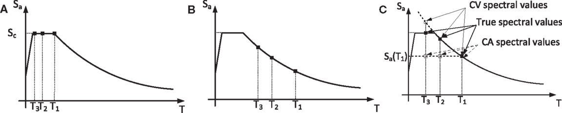
Figure 3. Location of the first natural periods in the response spectrum: (A) all in the CA region, (B) all in the CV region, and (C) some in the CV region while others in the CA region.
Characteristic values for Tc in Israel usually range from 0.2 s to about 0.8 s in extreme cases. Most of the structures retrofitted are four stories and more, while two additional stories could be built and sold to fund the retrofitting expenses. Thus, the structures analyzed are usually six stories and more. Frame structures of that height, in old buildings that were not seismically designed, usually possess fundamental periods of about 1.2–1.8 s. Thus, although in many cases, most relevant modes will fall within the constant velocity region, it is not uncommon to find cases where periods of some relevant modes fall within the constant velocity region while those of other modes fall within the constant acceleration region. In such cases, the responses of interest attained assuming that the periods of all relevant modes fall within the constant velocity region will serve as upper bounds. This is because the spectral accelerations of the higher modes, computed based on a constant velocity spectrum, are higher than the actual ones (Figure 3C). Similarly, the responses of interest attained assuming that the periods of all relevant modes fall within the constant acceleration region will serve as lower bounds. This is because the spectral accelerations of the higher modes, computed based on a constant acceleration spectrum, are lower than the actual ones (Figure 3C). Note that, in this case, Sa(T′) is taken as the spectral acceleration at the fundamental period of the retrofitted system, that is different from Sc. It should be noted that, for the frame, responses the upper bound and lower bound were found to be very close. That is, the frame responses are not considerably affected by higher modes contributions. However, if viscous dampers alone are used as connections, the upper bound and lower bound for wall responses were not as close. Nonetheless, the values of these responses, as will be shown later on, were much smaller than those attained with a rigid connection. Thus, for the sake of comparing alternatives, and for initial design, this approach leads to reasonable results.
Dimensional Analysis
Taking advantage of the physics of the problem reduced the number of controlling parameters from nine to seven. While this presents a significant simplification of the problem, a parametric study with seven controlling parameters is still complex to manage, present, and analyze. A further reduction of the number of controlling parameters is thus desired. This is done by means of dimensional analysis [see, e.g., Barenblatt (2003)]. The origins of dimensional analysis are probably motivated by experimental research where the number of required experiments may be drastically decreased. The use of such tools in numerical parametric studies has also been taken advantage of [e.g., Makris and Black (2004a,b) and Lavan (2012)]. Here, the π theorem is adopted.
The first stage of the π theorem is choosing the repeating variables. As the problem at hand involves three independent dimensions, e.g., length, mass, and time, the number of repeating variables may be up to three. Those are chosen as mf, GA, and H. This choice is made for several reasons: for one, it is convenient that all non-dimensional parameters and responses are normalized by known parameters. As in the retrofitting problem stated above the frame parameters are given, this seems a natural choice. This will later allow a simple comparison between various retrofitting alternatives as it could be directly done based on the non-dimensional parameters and responses (assuming that the periods of all relevant modes of all retrofitting alternatives fall within one region of the spectrum). Note also that this choice will lead, later on, to some non-dimensional parameters that are well known from the behavior of wall-frame systems in static loadings. This is important as some engineers already developed some intuition to the order of magnitude of reasonable values of such parameters for given cases. Furthermore, with this choice, a clear rational could be used to determine the range of values for the non-dimensional controlling parameters. This may prevent the parametric study, and the conclusions drawn from that, from considering cases that are not practical.
With mf, GA, and H as the repeating variables, using dimensional analysis theory, the following non-dimensional controlling parameters are attained:
The first of these parameters is the ratio of wall mass to frame mass. The second is the relative frame stiffness to wall stiffness. This is very well known as α⋅H in wall–frame systems in static loads (Stafford Smith and Coull, 1991). Finally, the third and fourth parameters represent the relative EDD damping and stiffness, respectively.
From the dimensional analysis, the non-dimensional responses of interest are attained as well. Those are
Range of Values for the Controlling Parameters
The application considered herein focuses on an existing frame structure retrofitted with new walls and dampers. These walls would usually carry their self-weight only. Thus, practically, the seismic mass to be carried by the frame is larger than that taken by the wall. The range of values for the seismic mass carried by the wall to that carried by the frame is thus taken as .
In general, the range of values for the parameter α⋅H extends from 0, when the wall is infinitely stiff compared to the frame, to infinity, when the frame is infinitely stiff compared to the wall. For the application considered herein, the practical range of values is closer to the first case. This is both because the existing frames are usually flexible and because the considered buildings are low to medium-rise. Thus, values of were considered. It is important to emphasize that values smaller than 0.1 were also analyzed and led to responses practically identical to those attained with 0.1.
Theoretically, the range of values for the damping coefficient of the dampers extends from 0 to infinity. Although the damping is very well utilized in the considered structural system, it is unlikely that practical use will be made of damping that would lead to very large damping ratios in the first modes, or even over-damped first modes. Thus, a preliminary study was conducted to tune the upper bound for the non-dimensional parameter to try to avoid such excessive damping as much as possible. The values of πc: 0, 0.1, 0.2, 0.3, 0.4, 0.5, 0.6, 0.7, and 0.8 were therefore adopted.
The range of values for the stiffness of the dampers can also, theoretically, span from 0 to infinity. The latter represents a rigid connection between the frame and the wall. As both 0 and a relatively stiff damper are practical, the values for this parameter were chosen so as to lead to a good distribution in terms of the responses of interest. These are πk: 0, 4.8, 13.6, 8 × 10⁸.
Analysis Approach
As indicated earlier, a discretized model is used for the analysis. The number of stories in this model was taken as 6, as this is believed to be the most common number of stories in such systems in Israel. Estimation of the potential errors in adopting the “smeared“ properties and responses attained with a 6 story model, for structures with a different number of stories, was then carried out. This was done via analyses of models with different number of stories ranging from 4 to 50. Those showed errors of ±3% in most responses of interest. In some extreme cases, a few responses were off by −8% to +10%.
The equations of motion of the discretized model subjected to an input ground motion are given as follows:
where M, C, and K are the mass, damping, and stiffness matrices, respectively; x(t) is the vector of coordinate displacements; an overdot represents a derivative with respect to time, t; and f(t) is a vector of loads. It should be emphasized that the considered systems include mechanical dampers. In general, and in the cases considered here, in particular, such systems may not qualify the Caughey criterion (Caughey and O’Kelly, 1965). Thus, for the purpose of analyzing such systems while modeling the seismic hazard via a response spectrum, use is made of a complex modal spectral analysis. Out of the procedures available for complex modal spectral analysis [e.g., Singh (1980), Takewaki (2004), and Song et al. (2008)], the one proposed by Song et al. (2008) was adopted and programed in Matlab. Using this approach, the equations are first brought to their following state-space form [see, e.g., Soong (1990)]:
Here,
Solving the eigenvalue problem corresponding to the homogeneous counterpart of Eq. 4 leads to the eigenvalues, λi, in the complex numbers domain from which the natural frequencies and damping ratios could be evaluated as follows:
where |⋅| and real(⋅) represent the absolute and the real part of a complex number, respectively. For each complex eigenvalue, a corresponding complex eigenvector (mode shape) could be computed. From the complex eigenvalues and mode shapes, the following contribution of the complex mode i and its conjugate to a response of interest could be assessed:
where A0i and B0i are computed based on the eigenvalue and mode shape i and its conjugate, and is the spectral displacement corresponding to the natural period and the damping ratio of these modes. Similarly, if real (overdamped) modes are attained, the contribution of the overdamped mode i could be assessed as follows:
where is computed based on the eigenvalue and mode shape i, and is the spectral displacement corresponding to the natural period of that mode. Finally, the contributions of the various modes could be combined using various combination rules. One of those rules, which was adopted here, is the GCQC (Song et al., 2008).
Equations 7 and 8 require the spectral displacements of underdamped and overdamped SDOF systems, respectively. Those of the underdamped systems were evaluated by modifying the 5% damping spectral accelerations using the following factor:
where ξ is the damping ratio as a value (not in percent). This factor is given in Eurocode 8 (CEN-Comité Européen de Normalisation, 2003) with a lower bound of 0.55. This factor, without the lower bound, was compared with the results presented by Ramirez et al. (2001) up to 99.99% damping with good agreement. Thus, it was adopted as is, with no lower bound. The spectral displacements of the overdamped modes, where applicable, were evaluated using the approach presented by Song et al. (2008).
In order to verify the validity of the analysis approach and the Matlab code, a comparison of the responses attained using this code with those attained using time history analyses was made with good agreement. In this comparison, the displacements of the SDOF systems representing the modes were evaluated using time history analyses.
Once a verification of the analysis engine was made, a comprehensive parametric study that includes the range of parameters indicated in Section “Range of Values for the Controlling Parameters” was carried out. The results of the parametric study, that present the attained non-dimensional responses of interest as a function of the non-dimensional controlling parameters, are presented in section “Parametric study results and discussion”.
Retrieving the Dimensional Responses of Interest
The non-dimensional responses are assessed in this study as part of the parametric study. The parametric study results are presented in section “Parametric study results and discussion”. Once a solution for the non-dimensional system is at hand, with known non-dimensional responses of interest (the π values in Eq. 2), the dimensional responses of interest are retrieved using Eq. 2.
Parametric Study Results and Discussion
Presentation of the Parametric Study Results
Although great efforts were made to reduce the number of controlling parameters, their number amounts to four, for each region of the spectrum. Thus, the results are presented in separate graphs for each region of the spectrum. In addition, each response of interest is presented in a dedicated matrix of graphs. In this matrix, each column has a different value of πs while each row has a different πm. This is depicted in Figure 4A. Furthermore, in each “cell” of this matrix lines are plotted to present the response of interest as a function of πc. Each of these lines is plotted for a different value of πk. This is depicted in Figure 4B. These represent connections by viscous dampers (continuous blue); a flexible spring (πk = 4.8) and a viscous damper (dashed green); a stiffer spring (πk = 13.6) and a viscous damper (dash-dotted red), and; a stiff connection (dotted black). Some results of the parametric study will be now presented and discussed. Results related to other responses of interest could be found in Supplementary Material.
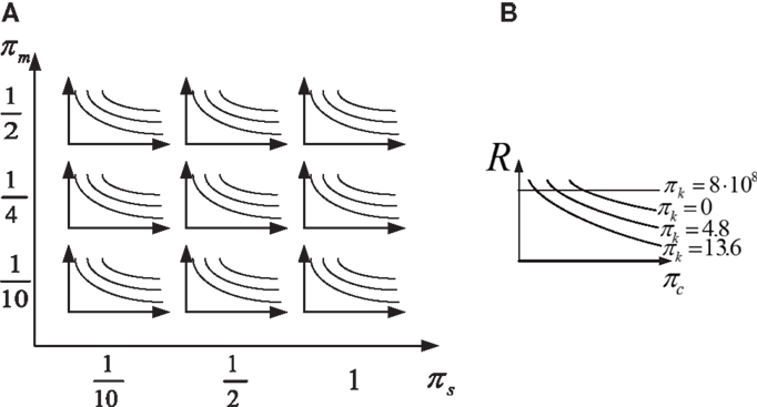
Figure 4. General preview of a typical response presentation: (A) the matrix of graphs, (B) a cell in the matrix representing given wall and frame.
Natural Periods
The non-dimensional fundamental period of the system is presented in Figure 5. As can be seen, a connection with viscous dampers only retains the fundamental period of the frame (estimated using πc = 0). In some systems having values of πs = 1 a large damping leads to an increase in the fundamental period. In these cases, the first mode was found to be overdamped. When either springs are added, or rigid connections are used, the natural period decreases drastically. This may have a huge effect on the forces attracted by the system, as will be discussed later on.
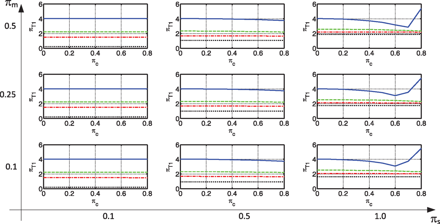
Figure 5. Natural period of the coupled system.
Responses of Interest Related to the Frame
The first frame response of interest is its inter-story drift. This is presented in Figures 6A,B for the constant velocity and constant acceleration regions, respectively. As can be seen, a rigid connection between the frame and the wall, results in small inter-story drifts in the frame. This is more pronounced for small πs values, which indicate a large stiffness of the wall. This is because a rigid connection leads to the same displacements in the frame and the wall. When the connection is made with viscous damping only, small inter-story drifts can also be attained with a sufficiently large damping coefficient, especially in the constant velocity region. These drifts may be much smaller than those experienced by the bare frame (when a 0 value of the viscous damper is used). When the wall is not “infinitely” rigid, the drifts of the damped frame can sometimes be even as small as the ones attained with a rigid connection. With the decrease in wall stiffness, this is attained with a smaller amount of damping. When, in addition to damping, stiffness is added to the connection, the frame inter-story drift reduces considerably. This is true even if the amount of stiffness is relatively small. Another point that is worth noting is that, when a non-rigid connection is used, this response seems relatively insensitive to πm and πs. This is important in case there is some uncertainty with respect to structural properties. It should be noted that, while this discussion focused on the frame inter-story drift, similar trends were observed in some other frame responses (e.g., base shear, top displacement, and over-turning moment).
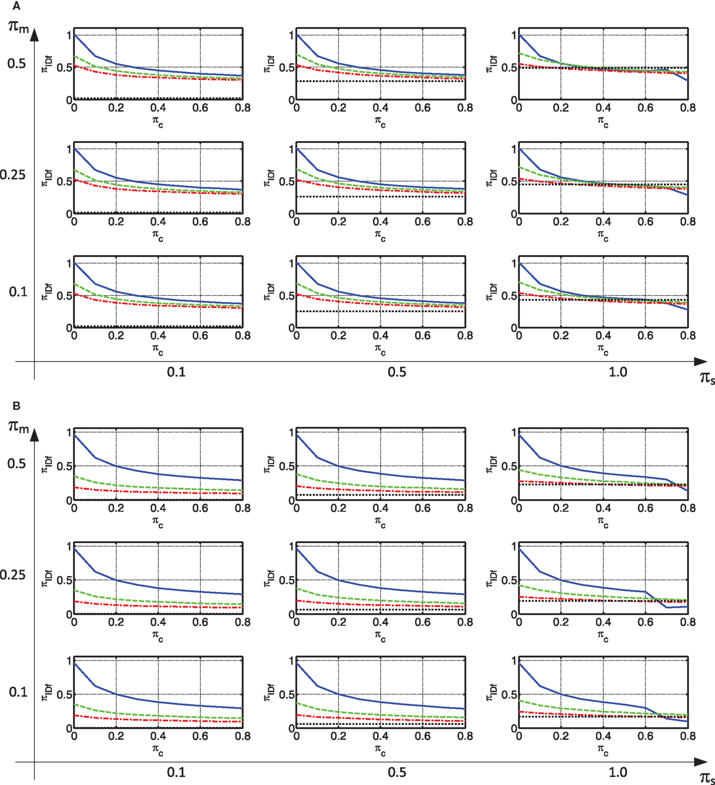
Figure 6. Max Frame Interstory Drift: (A) constant velocity region (B) constant acceleration region.
Another response of interest of the frame is its absolute acceleration. This is presented in Figures 7A,B for the constant velocity and acceleration regions, respectively. As can be seen, a rigid connection between the frame and the wall, results in extremely large absolute accelerations in the frame, especially in the constant velocity region. This is attributed to the fact that, with a rigid connection the floor mass is directly connected to the walls, which are relatively rigid. Thus, the periods of the modes that contribute to the frame displacements become very short, indicating large accelerations. When the connection is made with viscous damping only, the smallest absolute acceleration is usually attained. When, in addition to damping, stiffness is added to the connection, the absolute acceleration tends to somewhat increase.
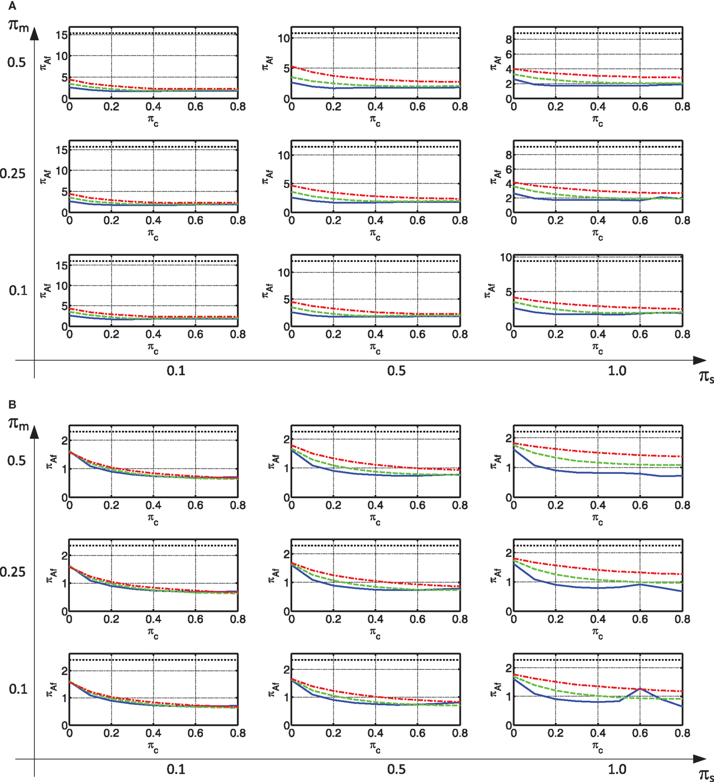
Figure 7. Max absolute acceleration of the frame: (A) constant velocity region (B) constant acceleration region.
Large absolute accelerations indicate damage to some non-structural components. This may be very important in structures that are expected to remain operational after the earthquake. Nevertheless, this is not their only importance. Absolute accelerations also indicate the level of inertia forces acting on the mass. These forces are to be transmitted from their point of action, through the existing slabs of the frame, to the lateral load resisting systems. These slabs are usually thin, and may sometimes be rib slabs. In addition, due to their year of construction, they sometimes are made of concrete of low quality. Thus, their ability to transfer these forces is limited, and is usually known with a large uncertainty. In addition, as new lateral load resisting systems exist, the path of the inertia forces may change considerably and be much different from the original one.
Responses of Interest Related to the Connection
The most important connection response of interest is the maximum peak connection force. It is strongly related to the feasibility of the retrofitting approach. While new dampers or connection elements can be designed to take these forces, they are connected to existing elements that are of limited given capacity. The maximum peak connection force is presented in Figure 8.
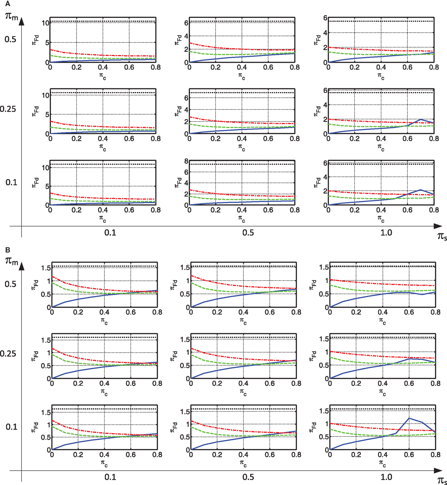
Figure 8. Max connection force: (A) constant velocity region (B) constant acceleration region.
As can be seen, in the case of a rigid connection, the connection force is extremely large, much larger than any other alternative. This is more pronounced in the constant velocity region. When the connection is made with viscous damping only, the smallest connection force is usually attained. When, in addition to damping, stiffness is added to the connection, the connection force increases. This increase is more pronounced with a small damping. For larger values of damping, the increase of connection force due to the addition of some stiffness is much less pronounced, and sometimes even a decrease is attained.
As indicated in the Section “Introduction,” large forces in the connecting elements are locally transmitted through the existing slabs of the building. These are limited in their given capacity. Furthermore, the large forces in the connections indicate that a large portion of the inertia forces acting on the slabs is transmitted to the new lateral load resisting system. As the path that these forces take from their point of action to the connections is much different from their original path to the old lateral load resisting system (frames), the slabs may not be able to withstand these forces. This is especially true if their magnitude is large. Thus, this response may lead to infeasibility of using a given connection type.
Responses of Interest Related to the Wall
The wall response of interest is the peak base over-turning moment (Figure 9). As can be seen, in the case of a rigid connection, the wall moment is larger than any other alternative. As in other responses, this is more pronounced in the constant velocity region. When the connection is made with viscous damping only, the smallest moment is usually attained. When, in addition to damping, stiffness is added to the connection, the moment increases. This increase is more pronounced with a small damping. For larger values of damping, the increase of moment due to the addition of some stiffness is less pronounced, and sometimes even a decrease is attained. It should be noted that, while this discussion focused on the wall base moment, similar trends were observed in some other wall responses (e.g., base shear).
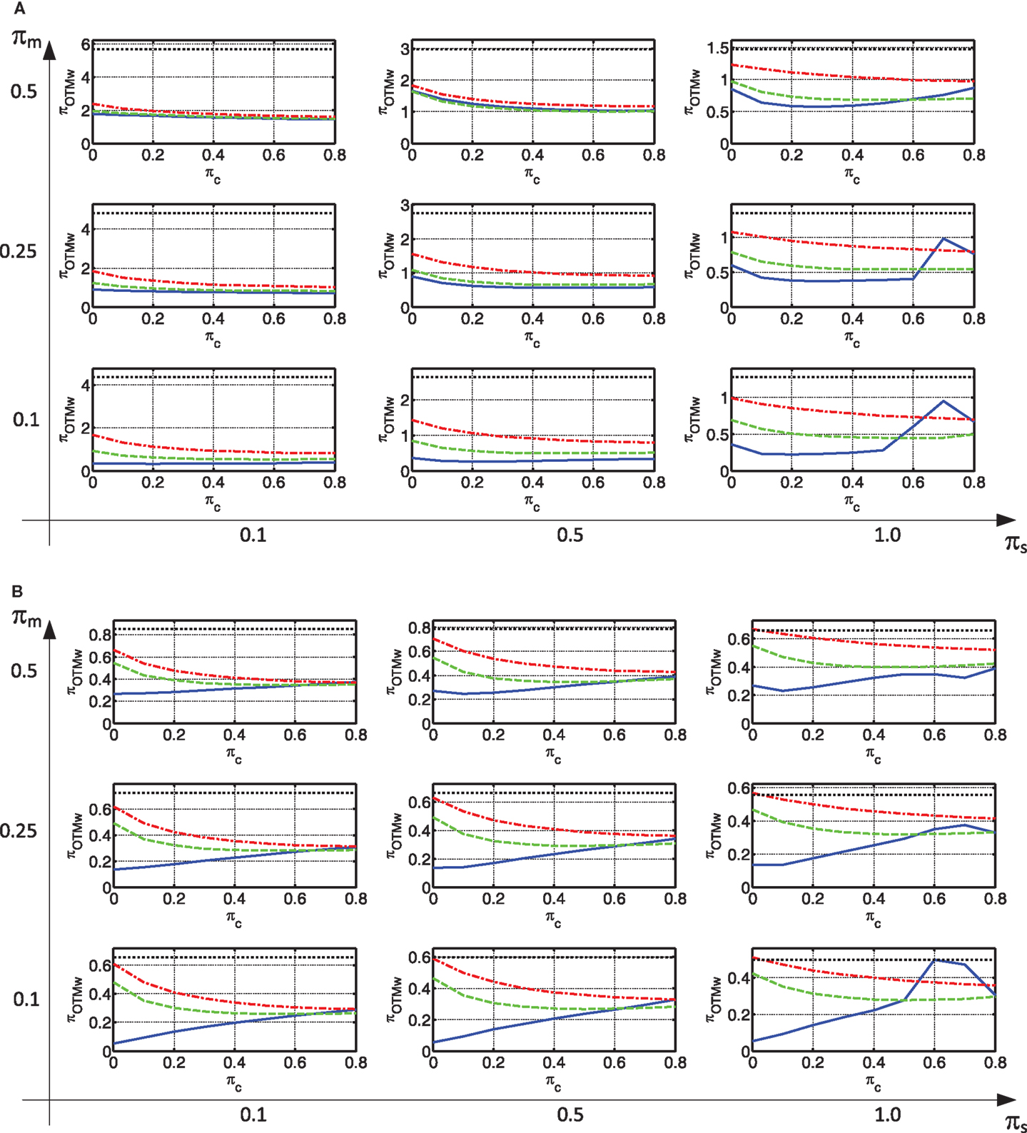
Figure 9. Wall base moment: (A) constant velocity region (B) constant acceleration region.
As indicated in the Section “Introduction,” large over-turning moments in the wall, with the small gravity forces acting on them, may lead to large tension in their foundations. Depending on the soil type, this may lead to very large foundations. In turn, this may lead to high retrofitting costs and may sometimes fail a retrofitting project. This becomes more and more of an issue with a growing number of stories.
Summary of the Parametric Study
In view of the results presented above, frame inter-story drifts are the smallest when a rigid connection is used. Connections with viscous dampers and springs could also considerably reduce the drifts with respect to the bare frame, in some cases, even to the same levels as those attained with a rigid connection. When it comes to other responses such as frame absolute accelerations, connection force, and wall responses, a connection with dampers is much superior. Thus, it is suggested to use a connection with viscous dampers, possibly with springs as well, in any case that it can reduce the frame drifts to allowable values. This is especially true in the constant velocity region. It should be emphasized that a damped connection showed better reduction in all responses of interest, including frame drifts, with larger values of πs. While these may be realistic for other purposes (e.g., new buildings), for the retrofitting projects discussed those were not considered.
Example
The example considers the seismic retrofitting of an existing six story frame structure. Each story area is 460 m2 and its mass is 600 ton (300 ton at the roof). The typical story height is 3 m and the total height of the building is 18 m. Thus, the mass per unit height is 200 ton/m. The typical story stiffness of the frames assuming cracked cross sections is 106,300 kN/m leading to a natural period of the building of 1.8 s. This period compares well with the rule of thumb proposed by Crowley and Pinho (2004) for the yield period of existing European RC structures. This rule of thumb was originally proposed for better displacement estimation and, although thoroughly fundamented, it has not yet found its way to seismic codes. It should also be noted that if some inaccuracy in the natural period of the frame, or in its stiffness, exists, it affects the parameter πs. As can be seen from Figures 6–9, in this structure (πs ≈ 0.5, as will be calculated later) some inaccuracy in πs is not expected to considerably affect the values of the estimated responses (wall responses and frame displacements). It would, however, affect the frame force related responses. As those are computed based on the displacements and the frame stiffness at a later stage, conservative assumptions could be then made. The shear stiffness of the frame was computed as GA = Ks/h = 318,900 kN. The corner period of the representing spectrum is Tc = 0.4 s and its spectral pseudo-acceleration at 1.0 s is S1 = 2.5 m/s2.
Four cores were added to the building to supply shelter rooms. Their total area is 55 m2 per floor. Their total cracked moment of inertia is 387 × 106 kN⋅m2 and their mass per unit height is 52 ton/m. It is now desired to find the best connection type between the existing building and the new cores, as well as attain responses of interest for initial design.
The two known non-dimensional parameters of the system are πm and πs. Those are attained as and and rounded to 0.25 and 0.5, respectively. Thus, the center graph in each graph matrix represents the structure at hand. In order to attain the non-dimensional responses from the graphs, one needs to determine what spectrum region is relevant. Thus, the periods of the first three modes are evaluated for each retrofitting alternative. Using damping only, the periods are 1.74, 0.63, and 0.37 s. With a small stiffness added, the periods became 0.95, 0.54, and 0.36 s. With a medium stiffness added to the damper, values of 0.82, 0.48, and 0.33 s are attained. Finally, with a rigid connection, the periods drop to 0.4, 0.09, and 0.04 s. Thus, when a non-rigid connection is used, the constant velocity graphs will be adopted with Sa(T′) = 1.38 m/s2 that is evaluated at the fundamental period of the bare frame, 1.8 s. This is slightly conservative as the third mode has a period smaller then Tc. When a rigid connection is used, the constant acceleration graphs will be adopted with Sa(T′) = 6.25 m/s2 that is evaluated at the fundamental period of the rigidly connected system, 0.4 s.
The amount of damping that was adopted is πc = 0.4. Thus, the damping coefficient per unit height was taken as cd = 556.53 kN⋅s/m2. The responses of interest, which were evaluated using the non-dimensional graphs, are summarized in Table 1. For example, the inter-story drift angle of the frame with a viscous damping connection was computed as follows:
which translates to an inter-story drift of 0.00705⋅300 = 2.11 cm.
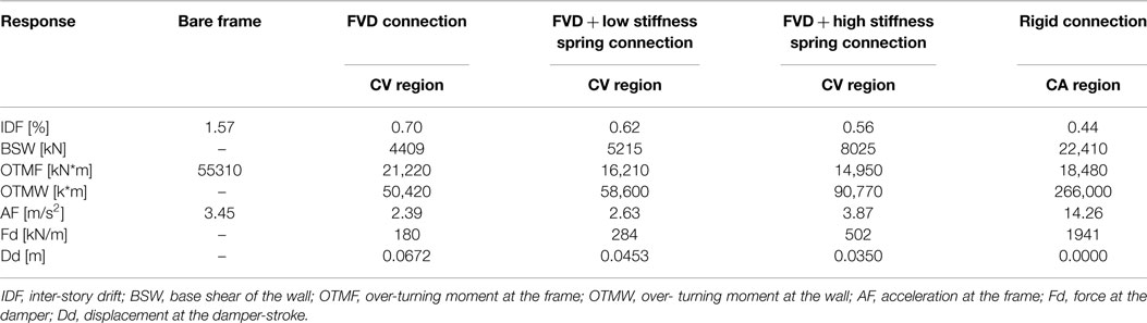
Table 1. Responses of interest using the various connection options.
As can be seen, with damping only, the inter-story drift was reduced by 55% (72% with a rigid connection). If such a drift could be accommodated by the frame, a large decrease could be attained in other responses compared to those of the rigid connection option: the wall over-turning moment is 19% of that of the rigid connection; The frame acceleration is 17% of that of the rigid connection and 70% of that of the bare frame, and; the connection force is 12% of that of the rigid connection. These huge differences are attributed to three factors: a viscous damper as a connection dissipates energy thus reduces the response; the forces in viscous dampers are out-of-phase with forces due to displacements and with inertia forces, and; the period of the damped system is much longer than that of the rigidly connected system. Smaller drifts than those attained with viscous damping only are attained when some stiffness is added to the damping. Those are accompanied, however, with some increase in other responses.
Discussion
This paper studied the seismic behavior of wall–EDD–frame systems in the context of retrofitting existing frame structures. The controlling non-dimensional parameters of such systems were identified and a rigorous parametric study was performed.
It was found that, frame inter-story drifts, as well as other frame responses, could efficiently be reduced when connecting the existing frame building to new walls with viscous dampers, with or without springs in parallel. Those responses were sometimes comparable to those attained with a rigid connection between the frame and the new wall. Other responses such as frame absolute accelerations, connection force, and wall responses, were much smaller when a connection with dampers was utilized in comparison to those attained with a rigid connection. These huge differences are attributed to three factors: a viscous damper as a connection dissipates energy thus reduces the response; the forces in viscous dampers are out-of-phase with forces due to displacements and with inertia forces, and; the period of the damped system is much longer than that of the rigidly connected system. Thus, it is suggested to use a connection with viscous dampers, possibly with springs as well, in any case that it can reduce the frame drifts to allowable values. This is especially true if the periods of the modes contributing to the bare frame response are within the constant velocity region. In addition, the sensitivity of the damped system to uncertainty in wall stiffness is much smaller than that of the system with a rigid connection.
Finally, tools were given for initial design of such retrofitting schemes. These enable both choosing the most appropriate retrofitting alternative and selecting initial values for its parameters, as demonstrated by the example.
Conflict of Interest Statement
The authors declare that the research was conducted in the absence of any commercial or financial relationships that could be construed as a potential conflict of interest.
Supplementary Material
The Supplementary Material for this article can be found online at https://www.frontiersin.org/article/10.3389/fbuil.2015.00007
References
Adachi, F., Yoshitomi, S., Tsuji, M., and Takewaki, I. (2013). Nonlinear optimal oil damper design in seismically controlled multi-story building frame. Soil Dynam. Earthquake Eng. 44, 1–13. doi: 10.1016/j.soildyn.2012.08.010
Aguirre, J. J., Almazán, J. L., and Paul, C. J. (2013). Optimal control of linear and nonlinear asymmetric structures by means of passive energy dampers. Earthquake Eng. Struct. Dynam. 42, 377–395. doi:10.1002/eqe.2211
Aida, T., Aso, T., Takeshita, K., Takiuchi, T., and Fujii, T. (2001). Improvement of the structure damping performance by interconnection. J. Sound Vib. 242, 333–353. doi:10.1006/jsvi.2000.3349
Aydin, E., Boduroglu, M. H., and Guney, D. (2007). Optimal damper distribution for seismic rehabilitation of planar building structures. Eng. Struct. 29, 176–185. doi:10.1016/j.engstruct.2006.04.016
Bhaskararao, A. V., and Jangid, R. S. (2007). Optimum viscous damper for connecting adjacent SDOF structures for harmonic and stationary white-noise random excitations. Earthquake Eng. Struct. Dynam. 36, 563–571. doi:10.1002/eqe.636
Bigdeli, K., Hare, W., Nutini, J., and Tesfamariam, S. (2015). Optimizing damper connectors for adjacent buildings. Optim. Eng.
Caughey, T. K., and O’Kelly, M. E. J. (1965). Classical normal modes in damped linear dynamic systems. J. Appl. Mech. 32, 583–588. doi:10.1115/1.3627262
CEN-Comité Européen de Normalisation. (2003). Eurocode8: Design of Structures for Earthquake Resistance. Part1: General Rules, Seismic Actions and Rules for Buildings. Brussels: European Committee for Standardization.
Christopoulos, C., and Filiatrault, A. (2006). Principles of Passive Supplemental Damping and Seismic Isolation. Pavia: IUSS Press.
Cimellaro, G. P., and Lopez-Garcia, D. (2011). Algorithm for design of controlled motion of adjacent structures. Struct. Contr. Health Monit. 18, 140–148. doi:10.1002/stc.357
Constantinou, M.C., and Symans, M.D. (1992). Experimental and Analytical Investigation of Seismic Response of Structures with Supplemental Fluid Viscous Dampers. Report No. NCEER-92-0032. New York, NY: National Center for Earthquake Engineering Research, State University of New York at Buffalo.
Crowley, H., and Pinho, R. (2004). Period-height relationship for existing European reinforced concrete buildings. J. Earthquake Eng. 8, 93–119. doi:10.1080/13632460409350522
Dargush, G. F., and Sant, R. S. (2005). Evolutionary aseismic design and retrofit of structures with passive energy dissipation. Earthquake Eng. Struct. Dynam. 34, 1601–1626. doi:10.1002/eqe.497
Enrique Luco, J., and De Barros, F. C. P. (1998). Optimal damping between two adjacent elastic structures. Earthquake Eng. Struct. Dynam. 27, 649–659. doi:10.1002/(SICI)1096-9845(199807)27:7<649::AID-EQE748>3.0.CO;2-5
FEMA 356. (2000). Prestandard and Commentary for the Seismic Rehabilitation of Buildings. Washington, DC: Federal Emergency Management Agency.
Gidaris, I., and Taflanidis, A. A. (2015). Performance assessment and optimization of fluid viscous dampers through life-cycle cost criteria and comparison to alternative design approaches. Bull. Earthquake Eng. 13, 1003–1028.
Gluck, N., Reinhorn, A. M., Gluck, J., and Levy, R. (1996). Design of supplemental dampers for control of structures. J. Struct. Eng. 122, 1394–1399. doi:10.1061/(ASCE)0733-9445(1996)122:12(1394)
Hatzigeorgiou, G. D., and Pnevmatikos, N. G. (2014). Maximum damping forces for structures with viscous dampers under near-source earthquakes. Eng. Struct. 68, 1–13. doi:10.1016/j.engstruct.2014.02.036
Huang, X., and Zhu, H. P. (2013). Optimal arrangement of viscoelastic dampers for seismic control of adjacent shear-type structures. J. Zhejiang Univ. 14, 47–60. doi:10.1631/jzus.A1200181
Kanno, Y. (2013). Damper placement optimization in a shear building model with discrete design variables: a mixed-integer second-order cone programming approach. Earthquake Eng. Struct. Dynam. 42, 1657–1676. doi:10.1002/eqe.2292
Kim, J., Ryu, J., and Chung, L. (2006). Seismic performance of structures connected by viscoelastic dampers. Eng. Struct. 28, 183–195. doi:10.1016/j.engstruct.2005.05.014
Landi, L., Lucchi, S., and Diotallevi, P. P. (2014). A procedure for the direct determination of the required supplemental damping for the seismic retrofit with viscous dampers. Eng. Struct. 71, 137–149. doi:10.1016/j.engstruct.2014.04.025
Lavan, O. (2012). On the efficiency of viscous dampers in reducing various seismic responses of wall structures. Earthquake Eng. Struct. Dynam. 41, 1673–1692. doi:10.1002/eqe.1197
Lavan, O. (2015). A methodology for the integrated seismic design of nonlinear buildings with supplemental damping. Struct. Contr. Health Monit. 22, 484–499. doi:10.1002/stc.1688
Lavan, O., and Amir, O. (2014). Simultaneous topology and sizing optimization of viscous dampers in seismic retrofitting of 3D irregular frame structures. Earthquake Eng. Struct. Dynam. 43, 1325–1342. doi:10.1002/eqe.2399
Lavan, O., and Avishur, M. (2013). Seismic behavior of viscously damped yielding frames under structural and damping uncertainties. Bull. Earthquake Eng. 11, 2309–2332. doi:10.1007/s10518-013-9479-7
Lavan, O., Cimellaro, G. P., and Reinhorn, A. M. (2008). Noniterative optimization procedure for seismic weakening and damping of inelastic structures. J. Struct. Eng. 134, 1638–1648. doi:10.1061/(ASCE)0733-9445(2008)134:10(1638)
Lavan, O., and Dargush, G. F. (2009). Multi-objective evolutionary seismic design with passive energy dissipation systems. J. Earthquake Eng. 13, 758–790. doi:10.1080/13632460802598545
Lavan, O., and Levy, R. (2005). Optimal design of supplemental viscous dampers for irregular shear-frames in the presence of yielding. Earthquake Eng. Struct. Dynam. 34, 889–907. doi:10.1002/eqe.458
Lavan, O., and Levy, R. (2006). Optimal peripheral drift control of 3D irregular framed structures using supplemental viscous dampers. J. Earthquake Eng. 10, 903–923. doi:10.1142/S1363246906002931
Lavan, O., and Levy, R. (2009). Simple iterative use of Lyapunov’s solution for the linear optimal seismic design of passive devices in framed buildings. J. Earthquake Eng. 13, 650–666. doi:10.1080/13632460902837736
Lavan, O., and Levy, R. (2010). Performance based optimal seismic retrofitting of yielding plane frames using added viscous damping. Earthquake Struct. 1, 307–326. doi:10.12989/eas.2010.1.3.307
Lin, J. L., Bui, M. T., and Tsai, K. C. (2014). An energy-based approach to the generalized optimal locations of viscous dampers in two-way asymmetrical buildings. Earthquake Spectra 30, 867–889. doi:10.1193/052312EQS196M
Lopez-Garcia, D., and Soong, T. T. (2002). Efficiency of a simple approach to damper allocation in MDOF structures. J. Struct. Contr. 9, 19–30. doi:10.1002/stc.3
Makris, N., and Black, C. J. (2004a). Dimensional analysis of rigid-plastic and elastoplastic structures under pulse-type excitations. J. Eng. Mech. 130, 1006–1018. doi:10.1061/(ASCE)0733-9399(2004)130:9(1006)
Makris, N., and Black, C. J. (2004b). Dimensional analysis of bilinear oscillators under pulse-type excitations. J. Eng. Mech. 130, 1019–1031. doi:10.1061/(ASCE)0733-9399(2004)130:9(1006)
Martínez, C. A., Curadelli, O., and Compagnoni, M. E. (2013). Optimal design of passive viscous damping systems for buildings under seismic excitation. J. Construct. Steel Res. 90, 253–264. doi:10.1016/j.jcsr.2013.08.005
Murase, M., Tsuji, M., and Takewaki, I. (2013). Smart passive control of buildings with higher redundancy and robustness using base-isolation and inter-connection. Earthquakes Struct. 4, 649–670. doi:10.12989/eas.2013.4.6.649
Nakashima, M., Lavan, O., Kurata, M., and Luo, Y. (2014). Earthquake engineering research needs in light of lessons learned from the 2011 Tohoku earthquake. Earthquake Eng. Eng. Vib. 13, 141–149. doi:10.1007/s11803-014-0244-y
Palermo, M., Muscio, S., Silvestri, S., Landi, L., and Trombetti, T. (2013). On the dimensioning of viscous dampers for the mitigation of the earthquake-induced effects in moment-resisting frame structures. Bull. Earthquake Eng. 11, 2429–2446. doi:10.1007/s10518-013-9474-z
Patel, C. C., and Jangid, R. S. (2010). Seismic response of dynamically similar adjacent structures connected with viscous dampers. IES J. A Civ. Struct. Eng. 3, 1–13.
Peng, Y., Mei, Z., and Li, J. (2014). Stochastic seismic response analysis and reliability assessment of passively damped structures. J. Vib. Contr. 20, 2352–2365. doi:10.1177/1077546313486910
Rama Raju, K., Ansu, M., and Iyer, N. R. (2014). A methodology of design for seismic performance enhancement of buildings using viscous fluid dampers. Struct. Contr. Health Monit. 21, 342–355. doi:10.1002/stc.1568
Ramirez, O. M., Constantinou, M. C., Kircher, C. A., Whittaker, A. S., Johnson, M. W., Gomez, J. D., and Chrysostomou, C. Z. (2001). Development and Evaluation of Simplified Procedures for Analysis and Design of Buildings with Passive Energy Dissipation Systems-Revision 01. Technical Report MCEER-00-0010. Buffalo, NY.
Richardson, A., Walsh, K., and Abdullah, M. (2013). Closed-form equations for coupling linear structures using stiffness and damping elements. Struct. Contr. Health Monit. 20, 259–281. doi:10.1002/stc.490
Silvestri, S., and Trombetti, T. (2007). Physical and numerical approaches for the optimal insertion of seismic viscous dampers in shear-type structures. J. Earthquake Eng. 11, 787–828. doi:10.1080/13632460601034155
Singh, M. P. (1980). Seismic response by SRSS for nonproportional damping. J. Eng. Mech. Div. 106, 1405–1419.
Singh, M. P., and Moreschi, L. M. (2001). Optimal seismic response control with dampers. Earthquake Eng. Struct. Dynam. 30, 553–572. doi:10.1002/eqe.23
Song, J., Chu, Y.L., Liang, Z., and Lee, G. C. (2008). Modal Analysis of Generally Damped Linear Structures Subjected to Seismic Excitations. Report No. MCEER-08-0005. New York, NY: Multidisciplinary Center for Earthquake Engineering Research, State University of New York at Buffalo.
Sonmez, M., Aydin, E., and Karabork, T. (2013). Using an artificial bee colony algorithm for the optimal placement of viscous dampers in planar building frames. Struct. Multidiscip. Optim. 48, 395–409. doi:10.1007/s00158-013-0892-y
Soong, T. T., and Dargush, G. F. (1997). Passive Energy Dissipation Systems in Structural Engineering. Chichester: John Wiley & Sons Ltd.
Stafford Smith, B., and Coull, A. (1991). Tall Building Structures: Analysis and Design. New York: John Wiley & Sons.
Sun, H. S., Liu, M. H., and Zhu, H. P. (2014). Connecting parameters optimization on unsymmetrical twin-tower structure linked by sky-bridge. J. Cent. S. Univ. 21, 2460–2468. doi:10.1007/s11771-014-2200-4
Takewaki, I. (1997). Optimal damper placement for minimum transfer functions. Earthquake Eng. Struct. Dynam. 26, 1113–1124. doi:10.1002/(SICI)1096-9845(199711)26:11<1113::AID-EQE696>3.0.CO;2-X
Takewaki, I. (2004). Frequency domain modal analysis of earthquake input energy to highly damped passive control structures. Earthquake Eng. Struct. Dynam. 33, 575–590. doi:10.1002/eqe.361
Takewaki, I. (2007). Earthquake input energy to two buildings connected by viscous dampers. J. Struct. Eng. 133, 620–628. doi:10.1061/(ASCE)0733-9445(2007)133:5(620)
Takewaki, I. (2009). Building Control with Passive Dampers: Optimal Performance-based Design for Earthquakes. Singapore: John Wiley & Sons Ltd. (Asia).
Trombetti, T., and Silvestri, S. (2004). Added viscous dampers in shear-type structures: the effectiveness of mass proportional damping. J. Earthquake Eng. 8, 275–313. doi:10.1080/13632460409350490
Trombetti, T., and Silvestri, S. (2006). On the modal damping ratios of shear-type structures equipped with Rayleigh damping systems. J. Sound Vib. 292, 21–58. doi:10.1016/j.jsv.2005.07.023
Trombetti, T., and Silvestri, S. (2007). Novel schemes for inserting seismic dampers in shear-type systems based upon the mass proportional component of the Rayleigh damping matrix. J. Sound Vib. 302, 486–526. doi:10.1016/j.jsv.2006.11.030
Tubaldi, E. (2015). Dynamic behavior of adjacent buildings connected by linear viscous/viscoelastic dampers. Struct. Contr. Health Monit. doi:10.1002/stc.1734
Tubaldi, E., Ragni, L., and Dall’Asta, A. (2015). Probabilistic seismic response assessment of linear systems equipped with nonlinear viscous dampers. Earthquake Eng. Struct. Dynam. 44, 101–120. doi:10.1002/eqe.2461
Zhang, R. H., and Soong, T. T. (1992). Seismic design of viscoelastic dampers for structural applications. J. Struct. Eng. 118, 1375–1392. doi:10.1061/(ASCE)0733-9445(1992)118:5(1375)
Zhang, W. S., and Xu, Y. L. (1999). Dynamic characteristics and seismic response of adjacent buildings linked by discrete dampers. Earthquake Eng. Struct. Dynam. 28, 1163–1185. doi:10.1002/(SICI)1096-9845(199910)28:10<1163::AID-EQE860>3.3.CO;2-S
Zhang, W. S., and Xu, Y. L. (2000). Vibration analysis of two buildings linked by Maxwell model-defined fluid dampers. J. Sound Vib. 233, 775–796. doi:10.1006/jsvi.1999.2735
Appendix
List of symbols
Keywords: seismic retrofitting, energy dissipation devices, passive control, viscous dampers, wall–frame systems
Citation: Lavan O and Abecassis D (2015) Seismic behavior and design of wall–EDD–frame systems. Front. Built Environ. 1:7. doi: 10.3389/fbuil.2015.00007
Received: 20 February 2015; Accepted: 03 June 2015;
Published: 24 June 2015
Edited by:
Nikos D. Lagaros, National Technical University of Athens, GreeceReviewed by:
Iolanda-Gabriela Craifaleanu, Technical University of Civil Engineering Bucharest, RomaniaVagelis Plevris, School of Pedagogical and Technological Education, Greece
Copyright: © 2015 Lavan and Abecassis. This is an open-access article distributed under the terms of the Creative Commons Attribution License (CC BY). The use, distribution or reproduction in other forums is permitted, provided the original author(s) or licensor are credited and that the original publication in this journal is cited, in accordance with accepted academic practice. No use, distribution or reproduction is permitted which does not comply with these terms.
*Correspondence: Oren Lavan, Faculty of Civil and Environmental Engineering, Technion – Israel Institute of Technology, 837 Rabin Building, Haifa 32000, Israel, lavan@tx.technion.ac.il