CAD-Integrated Parametric Lightweight Design With Isogeometric B-Rep Analysis
 Ann-Kathrin Goldbach
 Anna M. Bauer
 - TUM Department of Civil, Geo and Environmental Engineering, Chair of Structural Analysis, Technical University of Munich, Munich, Germany
The complex geometries of lightweight structures can easily be modeled with modern CAD systems that use NURBS. Isogeometric B-Rep Analysis (IBRA) adopts the NURBS geometries along with their topology for the analysis model, which can thus fulfill both design purposes and solve structural problems in one software environment. Especially in lightweight design, which is characterized by a strong interaction between shape and structural behavior, this presents a major advantage. Results can be used as a new input to consecutive analyses within this novel approach. This is especially useful for the simulation of construction stages or in the design cycle of membrane structures, where mechanically driven optimizations, such as formfinding and cutting pattern generation, as well as structural analysis, are dependent on each other. This paper focusses on parametric design with IBRA and the advantages of the uniform model description and workflow. Not only geometrical but also mechanical properties can be parameterized and thus offer a large variety of options to explore for designers as well as engineers. In addition to the possibility of optimization through formfinding methods, the provided framework can conveniently be combined with other tools and thus be extended by external optimization loops where geometry and structural parameters are modified simultaneously. The successful integration of parametric IBRA in a CAD environment, such as Rhino and Grasshopper is presented. Selected examples demonstrate the significance of the CAD-integrated unified workflow for the interactive analysis loops of lightweight structures.
1. Introduction
The aim of lightweight design is to build structures with a minimal use of materials and an optimized utilization of the material's strength. In order to achieve this, shape optimization is often performed with the aim of reducing bending moments and hence section heights. Additionally, the application of pre-stress is often used to ensure no compression in tensile structures or to add stiffness to active bending structures. The interaction of form and force needs to be considered in order to design efficient lightweight structures. Formfinding is a method that can find equilibrium surfaces for tensile (cable and membrane) and compressive (grid and shell) structures. It can also provide equilibrium shapes for so-called hybrid structures, which are a combination of tensile, compressive and bending elements. Several formfinding techniques have been developed, evolving from physical experiments like hanging models and soap films to numerical methods. As the relation of form and force is highly non-linear for lightweight structures regardless of the analysis type (i.e., formfinding, structural analysis etc.), the numerical model needs to be able to map the deformation and material response appropriately. This not only implies the modeling of geometrical and material non-linearities, but also constraint (and possibly contact) non-linearities. With the CAD-integrated approach, presented in this paper, all mentioned non-linearities are accounted for.
CAD-integrated analysis merges computational design and analysis by performing all tasks on one model. The idea of Isogeometric Analysis (IGA), as coined by Hughes et al. (2005), is to use the NURBS description of a CAD-model for both the geometry description and the base functions of the analysis model (see also Cottrell et al., 2009). This CAD-integrated analysis model can thus be created in the CAD software environment, reducing the effort of creating an analysis model by “skipping” the classical meshing process. The smooth NURBS geometries from CAD are preserved for the analysis, which is beneficial for complex geometries with high curvatures. The successful development and application of IGA for the analysis of lightweight structures with surface elements can also be found in Kiendl et al. (2010), Kiendl (2011), Benson et al. (2011), and Philipp (2017). Isogeometric B-Rep Analysis (introduced as IBRA by Breitenberger et al., 2015; Breitenberger, 2016) extends CAD-integrated analysis by also including the topological information of a CAD model. Trimmed multipatch NURBS surfaces can thus be considered for the analysis.
The design-through-analysis idea proposes an isogeometric approach to account for the interaction of form and force and was presented in e.g., Schillinger et al. (2012) and Philipp et al. (2016). The extension of IGA to optimization problems has been shown in Wall et al. (2008), Seo et al. (2010), and Kiendl et al. (2014) among others. Guo et al. (2018) and Teschemacher et al. (2018) focus on the IGA workflow and data processing. Furthermore, the topic of analysis-suitable geometry creation for IGA was presented in Schmidt et al. (2010).
CAD-integrated parametric design allows for a fast and convenient exploration of both the geometrical and mechanical properties of a structure. Stavric and Marina (2011) showed the significance of parametric design in architecture. A platform for parametric design with IGA was presented in Hsu et al. (2015), Alic (2018), and Herrema (2018). They follow the same ideas as Kiwi!3d which was used for the generation of exemplary structures in this contribution.
This paper shows different numerical methods for the design of lightweight structures in a parametric isogeometric environment. In addition to the mentioned publications that deal with IGA and lightweight structures, this contribution shows the benefits of linking different types of analyses and thus integrating construction stages. Within the CAD-integrated approach, it is not only possible to generate analysis models from scratch but also to adapt analysis models for consecutive simulations. Chapter 2 briefly explains the basis of CAD-FEM integration with Isogeometric B-Rep Analysis and Chapter 3 presents selected formfinding techniques for lightweight structures that significantly benefit from a parametric design environment. In Chapter 4, this is illustrated with a formfound shell and hybrid structure which are optimized through different formfinding methods.
2. NURBS-Based CAD-Integrated Analysis
This chapter introduces Non-Uniform Rational B-Splines (NURBS) and basic principles of Isogeometric B-Rep Analysis. Furthermore, the idea of CAD-integrated parametric design is briefly explained.
2.1. NURBS
The foundation of surface and curve description in CAD is the concept of Non-Uniform Rational B-Splines, or NURBS. The NURBS curve C(ξ) is described by the sum of its control points Pi and the related weighted (wi) B-Spline functions (Ni,p(ξ)), summarized as Ri,p(ξ) (see Equations 1 and 2). B-Splines are defined by their knot-vector Ξ and the polynomial degree p. More details on NURBS and B-Splines can be found in Piegl and Tiller (1997). Figure 1 shows a NURBS curve with different weights w4 of P4 and a NURBS surface with the control point net.
NURBS are used for the geometry representation as well as the basis functions for the mechanical analysis in IBRA. Consequently, the displacements are also described by the same basis functions. Note that the discrete degrees of freedom, here displacements ui, are also attributed to the control points of the NURBS geometry (Equation 3).
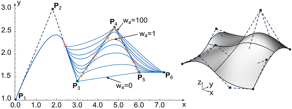
Figure 1. NURBS curve with different weight w4 of control point P4 (left). NURBS surface with control point net (right).
2.2. Isogeometric B-Rep Analysis
CAD-models are typically constructed as B-Rep models that consist of several curves and surfaces that are connected along their vertices, edges or faces. IBRA considers these extended properties of the CAD model for the analysis and consistently enhances the B-Rep entities with mechanical properties.
Furthermore, the NURBS curves and surfaces are defined in the geometry space as well as the parameter space (see Figure 2). The parameter space is generated by the curve- or surface parameters ξ, η and entails information, such as element edges and coupling definitions. Trimming operations are also applied in the parameter space: the geometry is separated into parts that lie inside or outside of a trimming curve. Complex geometries can be modeled efficiently by the application of trimming operations. These considerations lead to the concept of embedded elements by Bauer et al. (2017), that define mechanical properties, e.g., support and coupling conditions, inside the parameter space and thus independent of the FE mesh. A number of structural elements has been developed in this context, including trusses, beams, cables, membranes, plates and shells.
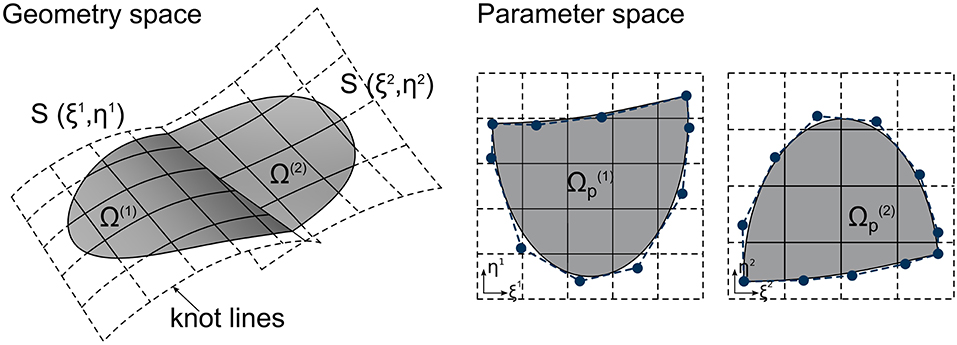
Figure 2. Trimming curves in geometry space (left) and parameter space (right).
2.3. CAD-Integrated Parametric Design
The unified approach to design and analysis through CAD-integration with IBRA offers various advantages for the design workflow, especially for structures with a strong interaction of form and force. In modern CAD-software, parametric design tools enable the exploration of a large design space. With the CAD-integrated approach, it is possible to parameterize geometrical and mechanical properties and vary them simultaneously. In-time answers with respect to design and structural options can be generated in linear and non-linear structural analyses as well as formfinding or other analyses. Optimization methods can be linked to the CAD-integrated model without difficulty.
The plugin (Kiwi!3d, 2019) was developed in a cooperation with structure GmbH in order to join parametric design tools and IBRA elements. It provides an interface with pre- and post-processing between the CAD-environment of Grasshopper and Rhino3d and the FE-code (Carat++, 2019).
3. Efficient Design Methods for Lightweight Structures
As the full CAD-description is available at any step of a CAD-integrated design process, the results (e.g., deformations, stresses) can be mapped onto the CAD-model. Like in a physical model, mechanical analyses can thus be used in order to generate shapes with a high precision of the geometry. This entails formfinding for membrane structures as well as inverted hanging models or pneumatic shapes.
In addition to the evaluation, CAD-integrated analysis results can easily be forwarded to consecutive analyses and the model can be manipulated inbetween. The design cycle of structural membranes is a relevant example for this, as the individual analysis steps are strongly linked and their interaction needs to be considered for a successful design (see e.g., Goldbach and Bletzinger, 2019 for more details). The formfound model is available as a full CAD-model and can thus be used to perform structural analysis. For the cutting pattern generation the CAD-integration is also highly beneficial, as simple trimming operations can be applied to define the seam lines. The single membrane parts are then available in the CAD-environment and a mounting analysis can evaluate the quality of the cutting pattern (smoothness of the mounted structure, stresses). This is done by simulating the erection process, i.e., “pulling” the membrane parts into their final position by setting geometric boundaries with edge cables and connection details. Lastly, having the 2D pattern inside the CAD-environment can also hold advantages for the manufacturing process, as this data can simply be forwarded.
3.1. Shape Generation With Forward Analysis Methods
Forward analysis methods for shape generation imply that a (often initially straight or flat) structure is subjected to an external loading and hence actively deformed in order to find an optimized shape. Two shape generation principles will be introduced here: hanging models to find bending-free geometries for shells and active bending that induces bending stiffness to elastic members through specific deformation.
In order to design efficient lightweight shells, physical models like hanging models can be helpful to generate shapes without bending. In the case of a hanging model, a cable net or a cloth is simply attached to the desired boundary positions and left to find its equilibrium shape under self-weight. As both cables and cloths can only carry tensile forces, a bending-free shape will be the result. By inverting the hanging geometry and choosing a rigid building material, a shell structure under pure compression can be built. Among the most prominent engineers who applied this technique were Antonio Gaudi and Heinz Isler (see Isler, 1961; Huerta, 2011). Heinz Isler created an entire encyclopedia of shapes with hanging models by allowing various cloth shapes to deform under self-weight and inverting them. Advanced numerical methods allow designers and engineers to perform computational analyses as a substitution of physical models. For example, a numerical hanging model can be created by solving a non-linear structural analysis under self-weight for a cable net or very thin shell. With the CAD-integrated approach, this leads to a deformed CAD-model that can then be used to define a grid or shell geometry (see section 4.1). In contrast to physical hanging models, the numerically formfound structures can be evaluated in full scale, which allows correct scaling of load and stiffness. With parametric design, the different boundaries and topologies of Isler's hanging models can easily be modeled and analyzed (see Figure 3 for selected examples). Besides the possibility of in-time analysis of CAD-integrated models, the high geometric quality brought about by the smooth NURBS surfaces is seen as a major advantage in this context.
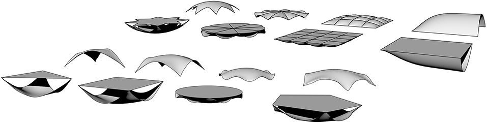
Figure 3. Numerically generated hanging models for a variety of flat shapes.
Active bending structures add bending stiffness to structural elements by actively deforming straight elements into a desired curved shape and fixing them there (see Figure 4). The example of a simply supported beam shows the effect: if subjected to a force at the supports, the initially straight beam deforms into a curved arch (see Figure 4). If the roller support is then fixed in the deformed position, the bending moment is “locked in,” providing additional stiffness against external loading. The interaction of shape and structural behavior is obvious, as higher curvature implies a larger bending moment and hence pre-stress. More details on active bending can be found in e.g., Lienhard et al. (2013). CAD-integrated analysis can simulate both the bending process and consecutive analyses conveniently. With the parametric approach, different options for the erection process, the initial shape and structural properties (i.e., material parameters, cross section) can be explored with regard to the final shape and pre-stress. This will be explained in more detail in Chapter 4.2.
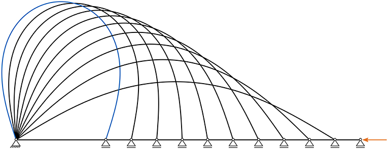
Figure 4. The principle of active bending by deforming an initially straight element into a curved one.
3.2. Inverse Optimization Methods
Tensile structures consisting of membranes and cables carry external loads through tension only. In order to achieve a safe level of stiffness and hence manageable deformations, tensile structures are usually pre-stressed. It is impossible to design and analyze these structures without considering the interaction of form and force. In formfinding, equilibrium surfaces or cable nets are found for the given pre-stress levels and boundary conditions. As only the pre-stress level is known and not the final geometry, formfinding can be categorized as an inverse optimization method. The same holds for the cutting pattern generation, where the problem of finding a suitable plane pattern geometry that can be assembled and stretched into the formfound geometry needs to be solved. In contrast to structural analysis, where the reference configuration X is known and the deformed configuration x is calculated, cutting pattern generation deals with the inverse problem. As exemplary approaches to formfinding and cutting pattern generation, the Updated Reference Strategy by Bletzinger and Ramm (1999) and Variation of Reference Strategy by Widhammer (2015) are briefly introduced. An overview of different formfinding methods can be found in Veenendaal and Block (2012) and Gosling et al. (2013). The fundamental equations of the Updated Reference Strategy are,
with virtual work δWURS, homotopy factor λ, Cauchy stresses σ, virtual Euler-Almansi strain δe, volume in current configuration v, external loading p, deformations δu, volume in reference configuration V, Second Piola-Kirchhoff stresses S and virtual Green-Lagrange strains δE. If the structure is in equilibrium, the virtual work is zero. The term is split into two parts by the homotopy factor λ. δWcur denotes the equilibrium in the deformed configuration whereas δWref is used as a stabilization term. The formfinding process of an initially arbitrary shape with given boundary conditions and pre-stress values can be seen in Figure 5.
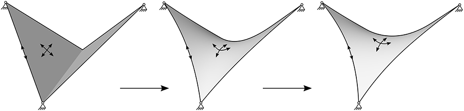
Figure 5. Formfinding process for a hypar with Updated Reference Strategy from left to right: an arbitrary starting geometry is updated until an equilibrium surface is found.
The basic idea of the Variation of Reference Strategy can be expressed in the following terms:
The minimum of the total potential energy is found at the stationary point of its derivative, i.e., δΠtotal = 0 with respect to a field of virtual material position vectors δX. The governing equation follows as,
with fixed target geometry x, plane configuration Ω0, motion χ(X, t), total potential energy Πtotal(X), virtual material position vectors δX and strain energy functions Ψ. The optimization of the cutting pattern in four pieces for a hypar is shown in Figure 6.

Figure 6. Optimization of the pattern geometry for a hypar with the variation of reference strategy.
The calculation of a minimal surface with e.g., URS can also be used in order to find the shape of a gridshell. The smooth surface description with NURBS preserves curvature information and thus facilitates the determination of mathematical lines on the surface. In Schling (2018) the resulting minimal surface was used to generate asymptotic lines for a gridshell pavilion.
4. Isogeometric Parametric Design Examples
The optimization of a large shell shape by computing a numerical hanging model (section 4.1) and the formfinding of a hybrid structure (section 4.2) will be shown as isogeometric design examples. All simulations were performed with the FE-code Carat++, with the plugin Kiwi!3D as a pre- and post-processing plugin to Rhino and Grasshopper.
4.1. Shell Formfinding
Kresge Auditorium is a large-scale shell structure at Massachusetts Institute of Technology designed by Eero Saarinen. Its shape is defined by an eighth of a sphere and does thus not follow a hanging form. This means that the shape was set without considering the mechanical consequences (i.e., bending moments), which lead to criticism on numerous accounts (see Ramm, 2004 for example) and substantial efforts in order to maintain the shell's stability. For example, the displacements of the structure were larger than expected and additional columns had to be added in the center of the edge beams. Nevertheless, it was constructed as a slender reinforced concrete roof supported by edge beams and the mentioned columns (see Figure 7).
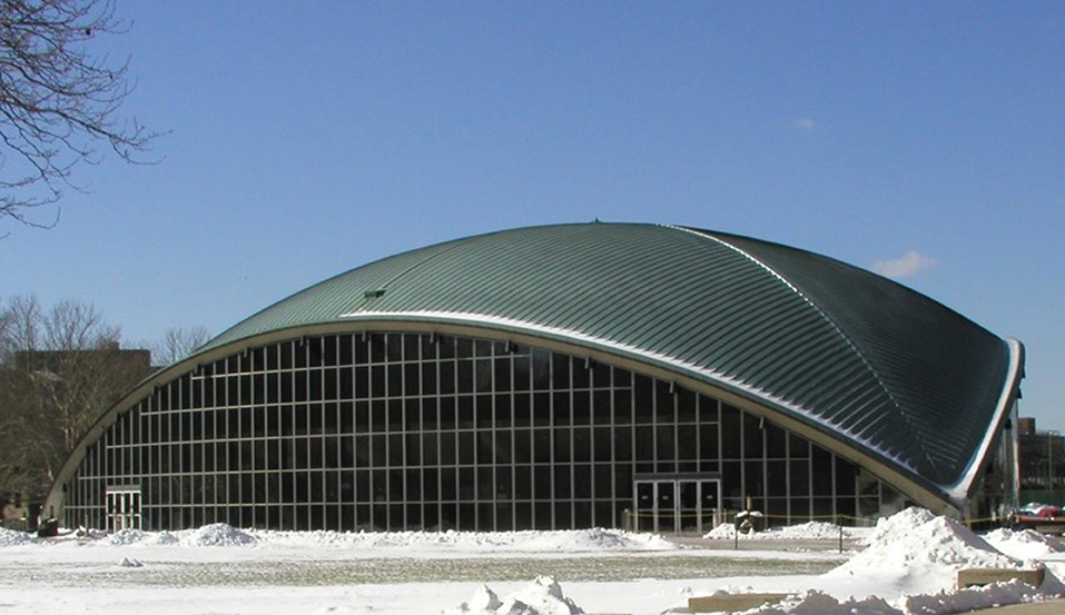
Figure 7. Kresge Auditorium at MIT.
In order to portray the effectiveness of formfinding through numerical hanging models for thin shells, the spherical Kresge Auditorium was modeled with a distance of 48 m between the support points and 0.09 m thickness. Concrete with a Young's modulus of 31,000 MN/m2 was chosen as a material. This “initial” shell geometry was then optimized by constructing a numerical hanging model, i.e., allowing the spherical shell to find its equilibrium shape by applying inversed self-weight in a geometrically non-linear structural analysis. To improve the stability of this analysis, the Young's modulus was multiplied by 10 and the thickness divided by 10, as was suggested by Längst et al. (2017). This leads to a significant reduction of the bending stiffness while the in-plane stiffness remains unchanged. Figure 8 shows the optimized shape generated by the numerical hanging model. The highpoints of the edges deform by 0.997 m vertically and 0.333 m toward the center of the dome.
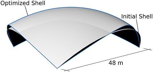
Figure 8. Spherical shape of Kresge Auditorium (initial shell) and numerically generated hanging model (optimized shell).
If subjected to an exemplary vertical loading of 0.54 kN/m2, the optimized shape shows less bending moments and smaller displacements (see Figure 9). The minimized bending moments allow for a minimal section height. Due to pure compression in the shell, the optimized geometry inherently leads to maximum material utilization. In consequence, the edge beam can be minimized and the supporting column can be omitted once a full structural analysis has been performed for the optimized shell geometry and section height. The parametric CAD-integrated analysis model allows the designer and engineer to investigate the hanging model with respect to numerous variations of the shell design. To name one example, the support situation might be of interest in more detail.
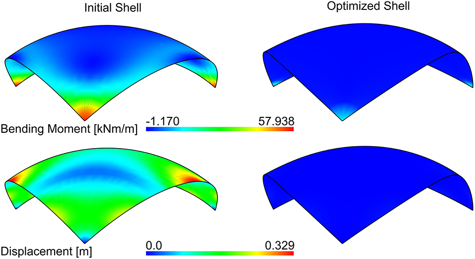
Figure 9. Bending moment and displacement of the initial and optimized shell geometry for the Kresge Auditorium under a vertical load of 0.54 kN/m2. Deformation of the arch's midpoint: for the initial shell 0.314 m vertically and 0.098 m toward the center; for the optimized shell 0.086 m vertically and 0.024 m toward the center.
4.2. Active Bending and Formfinding
As a second example, the case study of a hybrid structure that combines actively bent rods with a pre-stressed membrane is proposed, called the “beach bar.” Figure 10 shows the building process: the initially straight rods with lengths L1 and L2 are actively bent into curved ones by defining the final support position (by the parameters W and L0) and then moved into their upright positions, where their connecting points C1 and C2 are joined. In the next steps, the membrane is added along with its edge cables and fixed to the bent rods at M1 and M2. Formfinding is performed in order to find the equilibrium shape for the given pre-stresses P1 and P2 in the membrane and Pc in the cable and the given structural boundary conditions, including the bent rods as elastic supports. The final formfound hybrid structure is available as a full, mechanically enhanced CAD model. As the initial geometries are available, further analyses can account for the stress due to initial bending in the rods and thus accurately model their structural behavior. Typically, structural analysis would be performed in the next step for given external loadings. Furthermore, a cutting pattern generation is needed for the manufacturing plans of the membrane, with ncut defining the number and orientation of the pattern stripes in the final structure.
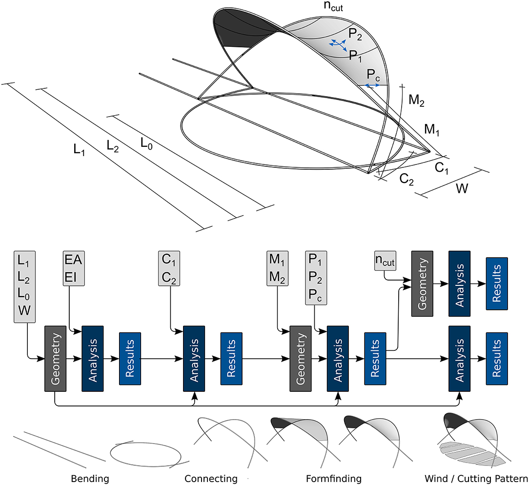
Figure 10. Parametric formfinding process of the beach bar with linked consecutive analyses: initially straight rods, actively bent rods, upright rods with joined connection points, added membrane elements, formfound hybrid structure, final beach bar model subjected to wind uplift and cutting pattern generation.
With a parametric setup of the beach bar model, several combinations of both geometrical and mechanical parameters can be explored. The proportions that were chosen for the presented structure are provided in Table 1. Figure 10 depicts the CAD-integrated parametric workflow of the mounting procedure. It can be seen that with IBRA, the input parameters can be varied at any stage of the mounting process without the necessity of rebuilding the model. All consecutive steps are automatically updated. Figure 11 shows selected parametric studies for the beach bar. The length L2 is varied while the connection point remains unchanged, leading to very different resulting shapes. The consequence of solely varying the width W between the rods is a drastic change in height and surface area covered by the membrane. Changing the mechanical parameter P1 leads to significant differences in the membranes' curvature which has a large effect on the load bearing behavior (threat of ponding etc.). Lastly, the seam lines are varied in number and orientation on the membrane, resulting in different cutting patterns. Since the membrane's surface is preserved as a full CAD-model in every analysis step (i.e., formfinding, structural analysis, and cutting pattern generation), it can be modified by standard CAD procedures like trimming. The uncorrupted surface description thus facilitates the exploration of pattern shapes and sizes. These can then be forwarded to manufacturing as CAD-models without further data processing steps.

Table 1. Proportions of the parameters for the beach bar with respect to L and P.
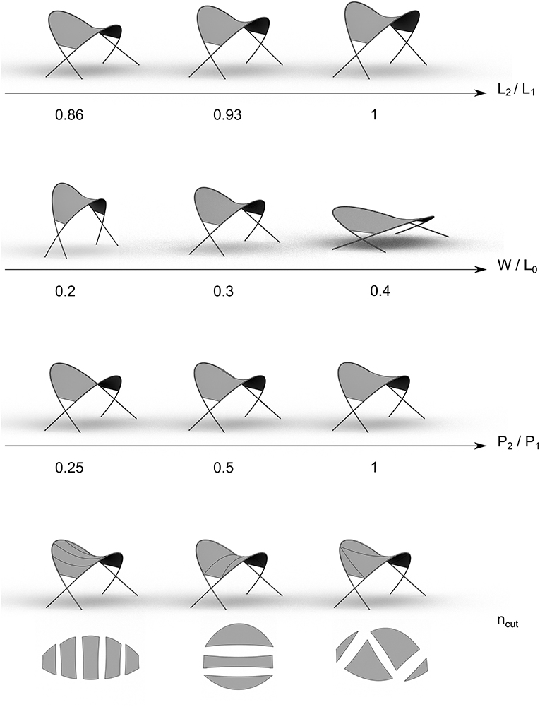
Figure 11. Selected parametric studies of the beach bar with Kiwi!3D for alterations of the proportions of L2/L1, W/L0, P2/P1, and orientation of ncut.
An external optimization algorithm could easily be added to the analysis workflow, in order to e.g., limit the membrane's maximum deformation under external loading. The simulation can be used as black box which automatically adapts to the parameters of the optimization and directly provides a response. This non-linear optimization problem is perfectly suited for zero-order optimization tools, also considering integer parameters. Due to the parametric set up, finite differences can easily be used to retrieve first-order gradients. The optimization can be applied at a certain stage of the process or consider the whole, highly non-linear mounting process.
5. Conclusion
This paper shows the potentials of CAD-integrated parametric design using Isogeometric B-Rep Analysis with a special focus on lightweight structures. The smooth NURBS models for complex geometries are mechanically enhanced and allow for a unified design workflow within a CAD-environment. The parametrization of both geometrical and mechanical properties allow designers and engineers to explore a large variety of options with respect to architectural aspects as well as structural behavior. Within the presented holistic framework, several consecutive analysis steps can easily be linked. This provides the possibility to account for the dependencies of the individual steps of a design loop. Additionally, CAD-integration allows for model processing between analysis steps without creating new analysis models and also utilizing CAD functionalities like trimming. The parametric CAD-integrated approach not only considers the strong interaction of form and force in lightweight structures, but facilitates efficient lightweight design by using this interaction in order to generate optimized geometries and structures. The benefits of this innovative methodology are illustrated with two selected examples. First, a numerical hanging model is calculated in order to formfind a shell geometry, leading to a bending-free load-bearing behavior for vertical loading. In the second example, active bending and formfinding analyses are linked in order to design a hybrid structure under consideration of all construction steps and hence accounting for the pre-stress from these steps. In addition to the presented structural optimization approaches, the uninterrupted, smooth workflow within the CAD environment provides the possibility to append an external optimization tool, can then provide the optimal input parameters for a defined response.
Data Availability Statement
All datasets generated for this study are included in the article/supplementary material.
Author Contributions
A-KG and AB were involved in developing the presented methods and software, planning, and writing of this paper. RW and K-UB provided the initial ideas, advised while developing the methods, and were involved in preparing and finalizing the paper.
Funding
This work was supported by the German Research Foundation (DFG) and the Technical University of Munich (TUM) in the framework of the Open Access Publishing Program.
Conflict of Interest
The authors declare that the research was conducted in the absence of any commercial or financial relationships that could be construed as a potential conflict of interest.
References
Alic, V. (2018). Computational methods in conceptual structural design (Dissertation), Lund University, Lund, Sweden.
Bauer, A. M., Breitenberger, M., Philipp, B., Wüchner, R., and Bletzinger, K.-U. (2017). Embedded structural entities in nurbs-based isogeometric analysis. Comput. Methods Appl. Mech. Eng. 325, 198–218. doi: 10.1016/j.cma.2017.07.010
Benson, D. J., Bazilevs, Y., Hsu, M.-C., and Hughes, T. J. R. (2011). A large deformation, rotation-free, isogeometric shell. Comput. Methods Appl. Mech. Eng. 200, 1367–1378. doi: 10.1016/j.cma.2010.12.003
Bletzinger, K.-U., and Ramm, E. (1999). A general finite element approach to the form finding of tensile structures by the updated reference strategy. Int. J. Space Struct. 14, 131–145. doi: 10.1260/0266351991494759
Breitenberger, M. (2016). CAD-Integrated Design and Analysis of Shell Structures, Volume Band 34 of Schriftenreihe des Lehrstuhls für Statik der Technischen Universität München. Lehrstuhl für Statik, Technische Universität München, München.
Breitenberger, M., Apostolatos, A., Philipp, B., Wüchner, R., and Bletzinger, K.-U. (2015). Analysis in computer aided design: nonlinear isogeometric b-rep analysis of shell structures. Comput. Methods Appl. Mech. Eng. 284, 401–457. doi: 10.1016/j.cma.2014.09.033
Carat++ (2019). Available online at: https://www.bgu.tum.de/st/software/forschung/carat/ (accessed December 13, 2019).
Cottrell, J. A., Hughes, T. J. R., and Bazilevs, Y. (2009). Isogeometric Analysis: Toward Integration of CAD and FEA. Chichester: John Wiley and Sons Ltd.
Goldbach, A.-K., and Bletzinger, K.-U. (2019). CAD-integrated parametric design cycle for structural membranes. J. Int. Assoc. Shell Spatial Struct. 60, 266–272. doi: 10.20898/j.iass.2019.202.024
Gosling, P. D., Bridgens, B. N., and Zhang, L. (2013). Adoption of a reliability approach for membrane structure analysis. Struct. Saf. 40, 39–50. doi: 10.1016/j.strusafe.2012.09.002
Guo, Y., Heller, J., Hughes, T. J., Ruess, M., and Schillinger, D. (2018). Variationally consistent isogeometric analysis of trimmed thin shells at finite deformations, based on the step exchange format. Comput. Methods Appl. Mech. Eng. 336, 39–79. doi: 10.1016/j.cma.2018.02.027
Herrema, A. J. (2018). A framework for isogeometric-analysis-based design and optimization of wind turbine blades (Dissertation), Iowa State University, Ames, IA, United States.
Hsu, M.-C., Wang, C., Herrema, A. J., Schillinger, D., Ghoshal, A., and Bazilevs, Y. (2015). An interactive geometry modeling and parametric design platform for isogeometric analysis. Comput. Math. Appl. 70, 1481–1500. doi: 10.1016/j.camwa.2015.04.002
Huerta, S. (2011). Structural design in the work of gaudí. 49, 324–339. doi: 10.3763/asre.2006.4943
Hughes, T. J. R., Cottrell, J. A., and Bazilevs, Y. (2005). Isogeometric analysis: CAD, finite elements, nurbs, exact geometry and mesh refinement. Comput. Methods Appl. Mech. Eng. 194, 4135–4195. doi: 10.1016/j.cma.2004.10.008
Kiendl, J. M. (2011). Isogeometric analysis and shape optimal design of isogeometric analysis and shape optimal design of shell structures (Dissertation), Technische Universität München, München, Germany.
Kiendl, J. M., Bazilevs, Y., Hsu, M.-C., Wüchner, R., and Bletzinger, K.-U. (2010). The bending strip method for isogeometric analysis of kirchhoff-love shell structures comprised of multiple patches. Comput. Methods Appl. Mech. Eng. 199, 2403–2416. doi: 10.1016/j.cma.2010.03.029
Kiendl, J. M., Schmidt, R., Wüchner, R., and Bletzinger, K.-U. (2014). Isogeometric shape optimization of shells using semi-analytical sensitivity analysis and sensitivity weighting. Comput. Methods Appl. Mech. Eng. 274, 148–167. doi: 10.1016/j.cma.2014.02.001
Kiwi!3d (2019). Available online at: https://www.kiwi3d.com (accessed December 13, 2019).
Längst, P., Michalski, A., and Lienhard, J. (2017). Integrated design approach for shell structures using isogeometric analysis. Nexus Netw. J. 19, 629–643. doi: 10.1007/s00004-016-0320-x
Lienhard, J., Alpermann, H., Gengnagel, C., and Knippers, J. (2013). Active bending, a review on structures where bending is used as a self-formation process. Int. J. Space Struct. 28, 187–196. doi: 10.1260/0266-3511.28.3-4.187
Philipp, B., Breitenberger, M., D'Auria, I., Wüchner, R., and Bletzinger, K.-U. (2016). Integrated design and analysis of structural membranes using the isogeometric b-rep analysis. Comput. Methods Appl. Mech. Eng. 303, 312–340. doi: 10.1016/j.cma.2016.02.003
Philipp, B. F. (2017). Methodological treatment of non-linear structural behavior in the design, analysis and verification of lightweight structures (Dissertation), Technische Universität München, München, Germany.
Piegl, L., and Tiller, W. (1997). The NURBS Book. Monographs in Visual Communication. 2nd Edn. Berlin; Heidelberg: Springer.
Ramm, E. (2004). Shape finding of concrete shell roofs. J. Int. Assoc. Shell Spatial Struct. 45, 29–39.
Schillinger, D., Dedé, L., Scott, M. A., Evans, J. A., Borden, M. J., Rank, E., et al. (2012). An isogeometric design-through-analysis methodology based on adaptive hierarchical refinement of nurbs, immersed boundary methods, and t-spline CAD surfaces. Comput. Methods Appl. Mech. Eng. 249–252, 116–150. doi: 10.1016/j.cma.2012.03.017
Schling, E. (2018). Repetitive Structures: Design and construction of curved support structures with repetitive parameters (Dissertation), Technische Universität München, München, Germany.
Schmidt, R., Kiendl, J. M., Bletzinger, K.-U., and Wüchner, R. (2010). Realization of an integrated structural design process: analysis-suitable geometric modelling and isogeometric analysis. Comput. Vis. Sci. 13, 315–330. doi: 10.1007/s00791-010-0147-z
Seo, Y.-D., Kim, H.-J., and Youn, S.-K. (2010). Isogeometric topology optimization using trimmed spline surfaces. Comput. Methods Appl. Mech. Eng. 199, 3270–3296. doi: 10.1016/j.cma.2010.06.033
Stavric, M., and Marina, O. (2011). Parametric modeling for advanced architecture. Int. J. Appl. Math. Inform. 5, 9–16.
Teschemacher, T., Bauer, A. M., Oberbichler, T., Breitenberger, M., Rossi, R., Wüchner, R., et al. (2018). Realization of CAD-integrated shell simulation based on isogeometric B-Rep analysis. Adv. Model. Simul. Eng. Sci. 5:19. doi: 10.1186/s40323-018-0109-4
Veenendaal, D., and Block, P. (2012). An overview and comparison of structural form finding methods for general networks. Int. J. Solids Struct. 49, 3741–3753. doi: 10.1016/j.ijsolstr.2012.08.008
Wall, W. A., Frenzel, M. A., and Cyron, C. (2008). Isogeometric structural shape optimization. Comput. Methods Appl. Mech. Eng. 197, 2976–2988. doi: 10.1016/j.cma.2008.01.025
Keywords: CAD-FEM integration, formfinding, free-form surfaces, isogeometric analysis, isogeometric B-Rep analysis, NURBS, parametric design
Citation: Goldbach A-K, Bauer AM, Wüchner R and Bletzinger K-U (2020) CAD-Integrated Parametric Lightweight Design With Isogeometric B-Rep Analysis. Front. Built Environ. 6:44. doi: 10.3389/fbuil.2020.00044
Received: 13 December 2019; Accepted: 24 March 2020;
Published: 15 April 2020.
Edited by:
Nikos D. Lagaros, National Technical University of Athens, GreeceReviewed by:
Mohammad Alhassan, Jordan University of Science and Technology, JordanAntonio Maria D'Altri, University of Bologna, Italy
Copyright © 2020 Goldbach, Bauer, Wüchner and Bletzinger. This is an open-access article distributed under the terms of the Creative Commons Attribution License (CC BY). The use, distribution or reproduction in other forums is permitted, provided the original author(s) and the copyright owner(s) are credited and that the original publication in this journal is cited, in accordance with accepted academic practice. No use, distribution or reproduction is permitted which does not comply with these terms.
*Correspondence: Ann-Kathrin Goldbach, ann-kathrin.goldbach@tum.de