Model-Free Identification of Hysteretic Restoring-Force Characteristic of Multi-Plane and Multi-Story Frame Model With In-Plane Flexible Floor
 Kenichirou Shintani
 Shinta Yoshitomi
 Izuru Takewaki
- 1Department of Architecture and Architectural Engineering, Graduate School of Engineering, Kyoto University, Kyoto, Japan
- 2Department of Architecture and Urban Design, Ritsumeikan University, Kusatsu, Japan
While linear system identification (SI) has been developed extensively, research advancement in the field of non-linear hysteretic SI is not satisfactory. An innovative method is proposed in this paper for identification of hysteretic restoring-force characteristics of three-dimensional (3D) building structures with in-plane flexible floors. The hysteretic restoring-force characteristics of vertical structural frames in the 3D building structure are identified from the measured floor horizontal accelerations together with the hysteretic restoring-force characteristics of floors without the assumption of hysteresis types or a priori knowledge of restoring force characteristics. Fourier expansion is applied to the time-history responses of story shear forces in vertical frames and in-plane shear forces in horizontal frames (floors). A batch processing least-squares estimation method for measured data is shown to be applicable to the identification of the Fourier coefficients on the story shear forces in vertical structural frames and those on the in-plane shear forces in floors. The proposed method is simple and direct because only Fourier expansion and batch processing least-squares estimation are required. Numerical simulations with and without noise are conducted for investigating the accuracy and reliability of the proposed method. It is demonstrated that the proposed method can identify successfully the hysteretic restoring-force characteristics of plane frames in 3D building structures with in-plane flexible floors.
Introduction
An innovative method is proposed in this paper for identification of hysteretic restoring-force characteristics of three-dimensional (3D) building structures with in-plane flexible floors which are caused by stairs opening etc. The 3D building structure is composed of multiple vertical and horizontal frames. The horizontal frames represent floors. The hysteretic restoring-force characteristics of vertical and horizontal frames are identified from the two-directional horizontal accelerations measured at floors. The vertical and horizontal frame-wise simultaneous identification of hysteretic restoring-force characteristics from the observed floor accelerations without the assumption of hysteresis types or a priori knowledge of restoring force characteristics is the most outstanding and novel point.
Investigations on identification of hysteretic restoring-force characteristics of structures have been conducted in the last four decades (Toussi and Yao, 1983; Cifuentes, 1984; Leontaritis and Billings, 1985; Masri et al., 1987, 1993; Loh and Chung, 1993; Kitada, 1998, 2000; Kitada et al., 2000; Li et al., 2004a,b; Saadat et al., 2004; Zhang and Sato, 2006; Ikhouance and Rodellar, 2007; Tasbihgoo et al., 2007; Worden and Manson, 2010; Brewick et al., 2016; Pelliciari et al., 2018). Although these investigations are versatile, the problem of physical parameter system identification of 3D building structures with mass and/or stiffness eccentricity is a tough problem (e.g., Omrani et al., 2012; Nabeshima and Takewaki, 2017; Shintani et al., 2017, 2019; Fujita and Takewaki, 2018). Compared to the previous researches using neural networks (Saadat et al., 2004; Tasbihgoo et al., 2007; Brewick et al., 2016), wavelet transforms (Kitada, 1998, 2000; Saadat et al., 2004), support vector regressions (Zhang and Sato, 2006), fast Bayesian bootstrap filter (Li et al., 2004b), multi-stage iterative approach (Li et al., 2004a), the present approach is suitable for vertical and horizontal frame-wise simultaneous identification of hysteretic restoring-force characteristics of structural frames with flexible floors within a small amount of computational load. In addition, no iteration is required and robustness to noise is assured owing to the use of Fourier expansion as a low-pass filter.
Many parameters in 3D building structures to be identified make the identification problem difficult. Omrani et al. (2012) tackled the problem in a statistical way for known stiffness eccentricity. Since the eccentricity cannot be defined in this paper because of the treatment of the model with flexible floors and the non-linear hysteretic behaviors, a completely different formulation will be necessary. Recently a new method of frequency-domain system identification was proposed by Nabeshima and Takewaki (2017) for linear stiffness-eccentric 3D building structures with in-plane rigid floors. Shintani et al. (2017) developed another method of system identification for linear 3D building structures with stiffness eccentricity and rigid in-plane stiffness of floors. Subsequently, Shintani et al. (2019) extended their method to a linear model with in-plane flexible floors. However, the development for identification of hysteretic restoring-force characteristics is strongly desired.
Structural health monitoring (SHM) was initiated many years ago as an innovative approach to damage detection and restoration of structures (Doebling et al., 1996; Boller et al., 2009; Takewaki et al., 2011). The system identification (SI) methodologies play a key role in SHM. Two major approaches in the field of SI are the physical-parameter (PP) SI and modal-parameter (MP) SI. Much attention has been directed to the MP SI (Hart and Yao, 1977; Agbabian et al., 1991; Nagarajaiah and Basu, 2009) because it can provide the global mechanical properties of a structural system and has a stable and robust characteristic. However, the MP SI cannot be applied to the identification problems of hysteretic restoring-force characteristics of structures because the mode cannot be defined in non-linear structures.
In PP SI, a direct method with the least-squares concept was introduced by Nakamura and Yasui (1999). Because of the necessity of too many points of measurement, it was applied only to simple 1D shear-type building models. On the other hand, Takewaki and Nakamura (2000, 2005) developed a unique SI concept based on the work by Udwadia et al. (1978) for a shear building model.
While linear system identification (SI) has been developed extensively, research advancement in the field of non-linear hysteretic SI is not satisfactory. An innovative method is proposed in this paper for identification of hysteretic restoring-force characteristics of 3D building structures with in-plane flexible floors due to stairs opening or without in-plane stiffness component (brace). The hysteretic restoring-force characteristics of vertical structural frames in the 3D building structure are identified from the measured floor horizontal accelerations together with the hysteretic restoring-force characteristics of floors. Fourier expansion is applied to the time-history responses of story shear forces in vertical frames and in-plane shear forces in horizontal frames (floors). It is demonstrated that a batch processing least-squares estimation method for measured data can identify successfully and directly the Fourier coefficients on the story shear forces in vertical structural frames and those on the in-plane shear forces in floors. The proposed method is simple and direct because only Fourier expansion and batch processing least-squares estimation are required. Numerical simulations with and without noise are conducted for investigating the accuracy and reliability of the proposed method. It is demonstrated that the proposed method can identify successfully the hysteretic restoring-force characteristics of plane frames in 3D building structures with in-plane flexible floors.
Modeling of Building With In-Plane Flexible Floors
The in-plane stiffness of floors is assumed to be finite. This situation results from the stairs opening or the design of floors without in-plane stiffness component, etc. Let a shear spring and a dashpot between two consecutive vertical frames at the same floor level express the in-plane shear stiffness of a floor element.
Consider a 3D shear building model of N-story, as shown in Figure 1A, which includes in-plane flexible horizontal floors. This 3D model is subjected to the one-directional horizontal ground acceleration ÿg with an inclination angle ϕ to the x direction. This model consists of n vertical frames parallel to the x axis and m vertical frames parallel to the y axis. The j-th vertical frame parallel to the y axis and the l-th vertical frame parallel to the x axis are denoted by xj(j = 1, … , m) and yl(l = 1, … , n), respectively. On the other hand, in the case where the notations, xj(j = 1, … , m − 1) and yl(l = 1, … , n − 1), are used between two consecutive vertical frames, these indicate the quantities related to span. The span length in the x direction and that in the y direction are denoted by and , respectively, as shown in Figure 1B. Let denote the floor mass located at the point of intersection of x and y direction frames in the i-th story. The horizontal stiffness of the yl and xj vertical plane frames in the i-th story are denoted by . On the other hand, let denote the in-plane shear stiffness of floor per unit length in the [xj, yl] span of the i-th story (see Figure 1C). More detailed explanation can be found in the reference (Shintani et al., 2019). Although these stiffnesses are used for the modeling of the objective building structures, only the hysteretic restoring-force characteristics of vertical frames and in-plane horizontal floors are identified directly in the present paper.
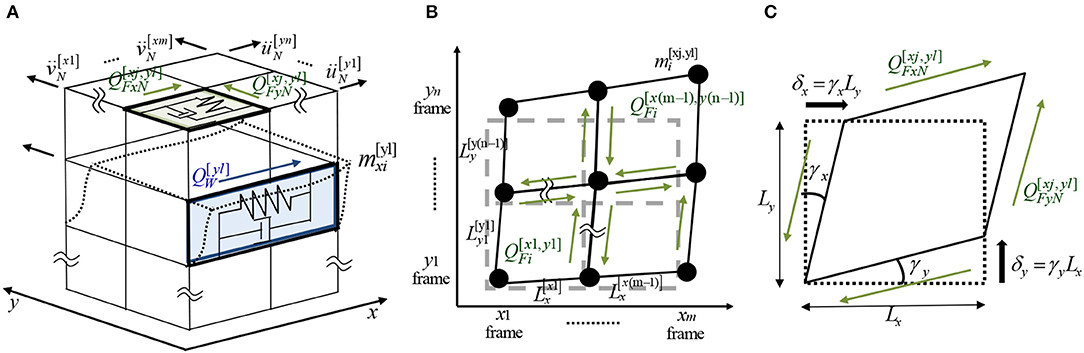
Figure 1. 3D shear building model consisting of vertical frames connected by in-plane flexible floors subjected to one-directional horizontal ground motion inclined to x axis, (A) overview, (B) plan, (C) in-plane floor deformation.
Modeling of Structural Behavior
Degrees of Freedom
The horizontal displacements of the i-th story in the l-th vertical frame parallel to the x axis and those in the j-th vertical frame parallel to the y axis are denoted by and , respectively. In this model, (m + n)N indicates the number of degrees of freedom. Let u[yl] = {} and v[xj] = {} denote the horizontal displacement vectors of N elements in x-direction and y-direction, respectively. Then the total displacement vector y can be expressed by,
Story Shear Force in Vertical Frame
Let and denote the x-direction story shear force at the yl vertical frame in the i-th story and the y-direction story shear force at the xj vertical frame in the i-th story, respectively, as shown in Figure 1A.
In-Plane Shear Force in Horizontal Frame (Floor)
Let and denote the x-direction in-plane shear force in the xj, yl span in the i-th story and the y-direction in-plane shear force in the xj, yl span in the i-th story, respectively, as shown in Figure 1B.
Equations of Motion
The equation of motion around the total mass at the yl frame in the i-th story may be expressed as
This equation is visualized in Figure 2. In Equation (6), is the sum of masses at the yl frame in the i-th story and is defined by
Similarly, the equation of motion around the total mass at the xj frame in the i-th story may be expressed as
where
The equations of motion of the overall system may be reduced to
where denotes the sum of the increment of the story shear force along height and the increment of the in-plane shear force along span and
Let and denote the sum of the increment of the story shear force along height and the increment of the in-plane shear force along span at the yl frame in the i-th story and the story shear force along height and the increment of the in-plane shear force along span at the xj frame in the i-th story, respectively, as shown in Figure 2. These quantities called “increment” are introduced to express the equations of motion compactly and independently of the story location and the span location. Then the overall expression consisting of and can be expressed by
Since the story shear forces in vertical frames and the in-plane shear forces in floors are non-periodic functions, those are expressed as follows by using Fourier expansion.
where , , , , , are the Fourier coefficients and T/2 denotes the number of Fourier coefficients.
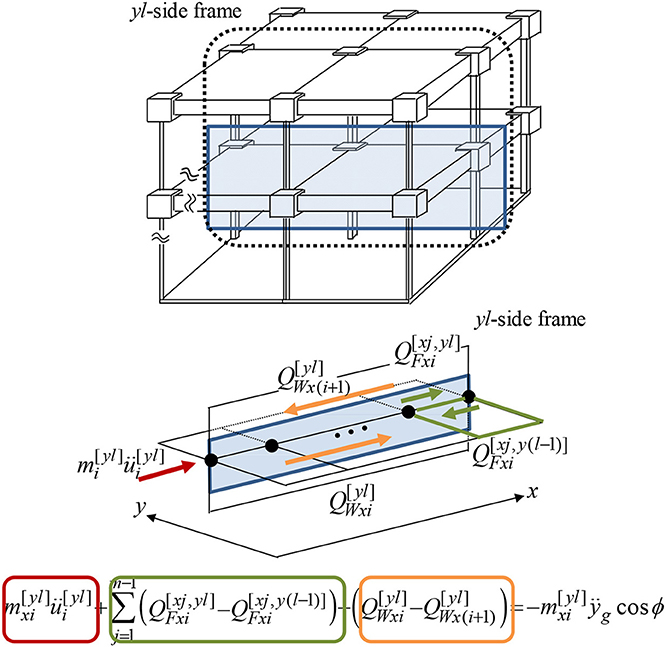
Figure 2. Dynamic equilibrium including story shear force in vertical frame and in-plane force in horizontal frame (floor).
Figure 3A shows a schematic diagram of Fourier expansion of the story shear force. The model is a one span (2 m) × one span (2 m) model of three stories. The time history of the story shear of the y1 frame in the first story is presented in Figure 3A.
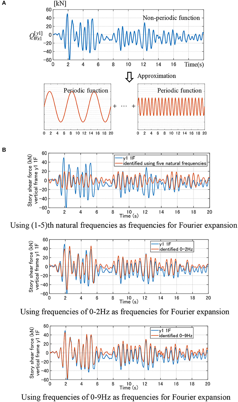
Figure 3. Fourier expansion of story shear force in vertical frame and its accuracy investigation depending on employed frequencies for Fourier expansion. (A) Fourier expansion of story shear force in vertical frame. (B) Accuracy investigation in terms of frequencies for Fourier expansion. (i) Using (1–5)th natural frequencies as frequencies for Fourier expansion. (ii) Using frequencies of 0-2Hz as frequencies for Fourier expansion. (iii) Using frequencies of 0–9 Hz as frequencies for Fourier expansion.
El Centro 1940 NS is employed as an input ground motion. This ground motion has been input at the incident angle π/6 from the x-axis. The frequency range 0–9 Hz is used. This is because the frequency range 0–9 Hz includes five peak frequencies indicating the principal modes. In addition, the frequency increment is set as 0.05 Hz. In this case, the number T/2 of Fourier coefficients is 180.
Figure 3B indicates the accuracy investigation depending on employed frequencies in Fourier expansion. In this figure, the figure (i) uses (1–5)th natural frequencies as frequencies for Fourier expansion, the figure (ii) employs frequencies of 0–2 Hz as frequencies for Fourier expansion, and the figure (iii) uses all frequencies of 0–9 Hz as frequencies for Fourier expansion. It can be observed that the use of only several lower natural frequencies is insufficient and the increase of employed frequency range enhances the accuracy.
The frequency range in Fourier expansion has to be selected in advance. The lower and upper bounds of the frequency range can be determined from the power and cross spectra of the ground acceleration and the recorded floor accelerations. The frequency increment in the frequency range can be determined from the number q of data points and the time increment dt of data in the rectangular window.
Formulation of Identification of Hysteretic Restoring-Force Characteristic in Vertical Frame and In-Plane Shear Force in Horizontal Frame (Floor)
A new formulation of system identification of 3D-frames with in-plane flexible floors is presented here for recorded floor accelerations. The restoring-force characteristics of vertical frames and horizontal frames (floors) are predicted and identified in the time domain. First, the story shear forces in vertical frames and the in-plane shear forces in horizontal frames (floors) are determined by using Fourier expansion and least-squares estimation. Then, the restoring-force characteristics of vertical frames and horizontal frames (floors) are evaluated by expressing the story shear forces in vertical frames and the in-plane shear forces in horizontal frames (floors) with respect to interstory drift or shear strain.
Let Θ denote the ensemble of the Fourier coefficients to be predicted.
and in Equation (23) are defined as follows.
where
In Equations (27), (28), (30), (31), (33), (34), , , , , , are the Fourier coefficients.
Since in Equation (10) consists of Fourier coefficients , , , and sine, cosine functions, the equations of motion, Equation (10), at time t can be expressed in terms of the coefficient matrix H(t), the constants Z(t) and the unknown parameters Θ by arranging the terms.
where the constants Z(t) and the coefficient matrix H(t) can be expressed by
HW(t) is the coefficient matrix of (n + m)N × T(n + m)N for vertical frames and is defined by
HF(t) is the coefficient matrix of (n + m)N × T(n − 1)(m − 1)N for floors. It is useful to take into account the relation of in-plane forces in floors with the equations of motion [see Equations (6), (8), (17), (18)]. Consider the columns from T{Nm(l − 1) + N(j − 1) + i − 1} to T{Nm(l − 1) + N(j − 1) + i} in HF(t). Only the components in rows of N(l − 1) + i, Nl + i, Nn + N(j − 1) + i, Nn + Nj + i are non-zero. HF(t) can be expressed symbolically as
The Equation (35) has to be satisfied at every time. The purpose at this stage is to predict Θ so as to minimize the following error.
The sum of squares of errors e(t) at every time from t = t1 to t = t2 can be expressed by
The minimization of the sum of squares of errors can be achieved by
Equation (44) provides the solution Θ.
Numerical Example
In this paper, data obtained from the time-history response analysis are used as the observed data. This treatment enables the accuracy investigation of the proposed method. For the investigation on numerical reliability, the case with noise will also be treated later.
Example of Model With Inner Vertical Frame
Consider a 2-story 2-span three-dimensional building frame as shown in Figure 4. One accelerometer has to be installed at every story in each vertical frame. For example, a two-component accelerometer (x-direction and y-direction) is sufficient to install at three inter-sections (x1-side frame and y1-side frame, x2-side frame and y2-side frame, x3-side frame, and y3-side frame) at every story (see Figure 4). The model parameters are shown in Table 1. For the time-history response analysis, an analysis model has to be set first. A normal bilinear hysteretic model is used both for the vertical frames and the horizontal frames. The second (post-yield)-stiffness ratio to the initial stiffness is assumed to be 0.4 both for the vertical frames and horizontal frames. The yield interstory drift for the vertical frames is set as 0.01(m) and the yield shear strain in the horizontal frames are set as 0.01 (relatively large yield strain is set for expressing a flexible floor). The damping coefficient is set so as to be initial stiffness-proportional (damping ratio for the lowest mode is 0.02). Two recorded ground motions, El Centro 1940 NS and Hyogoken-Nanbu 1995 (Kobe Univ. NS), are employed (see Figure 5). These ground motions are input at the incident angle π/6 from the x-axis. The data of 0–20 s are used for the identification of hysteretic restoring-force characteristics during 0–20 s and data of 20–40 s are used for those during 20–40 s.
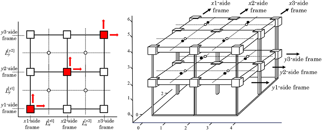
Figure 4. 2-story 2-span three-dimensional building frame.
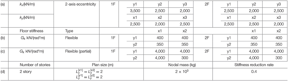
Table 1. Model parameters.
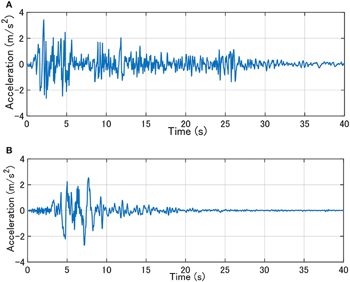
Figure 5. Recorded ground motions. (A) El Centro 1940 NS. (B) Hyogoken-Nanbu 1995 (Kobe Univ. NS).
Determination of Frequency Range
It is necessary to determine the frequency range for Fourier expansion. Figure 6 shows the transfer function evaluated from the ratio of the cross spectrum between the input and the response to the power spectrum of the input. It can be observed from Figure 6 that the frequency range 0–7 Hz is appropriate. This is because the frequency range 0–7 Hz includes all peak frequencies indicating the principal modes. In addition, the frequency increment is set as 0.05 Hz. In this case, the number T/2 of Fourier coefficients is 140.
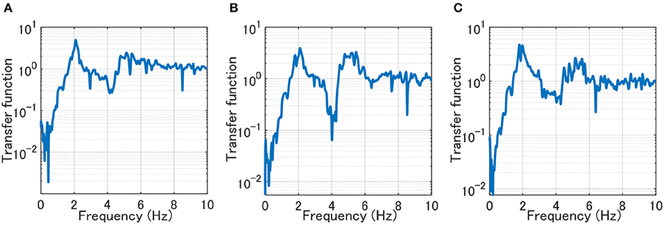
Figure 6. Reference distribution of transfer function. (A) Vertical frame y1_1F. (B) Vertical frame y2_1F. (C) Vertical frame y3_1F.
Identification Result
The building model with the parameters for the case (a), (b), (d) in Table 1 is subjected to the ground motions, El Centro 1940 NS and Hyogoken-Nanbu 1995 (Kobe Univ. NS).
Figure 7 shows the restoring force-shear strain hysteretic relations of horizontal frames and the restoring force-interstory drift hysteretic relations of vertical frames under El Centro 1940 NS. The exact loops were obtained from the time-history response analysis of the object building model corresponding to the parameters for the case (a), (b), (d) in Table 1. The shear strain in the restoring force-shear strain hysteretic relations of horizontal frames is obtained from
On the other hand, the interstory drift in the restoring force-interstory drift hysteretic relations of vertical frames is derived from
To present the detailed result of the proposed method, the comparison between the Fourier amplitude spectrum (exact/reference value) of the story shear force and the amplitude in terms of Fourier coefficients , (identified value) is shown in Figure 8. Figure 8A shows the Fourier amplitude spectrum divided by half of the number of data (ND/2 = 500) and Figure 8B indicates the amplitude in terms of the Fourier coefficients , . For reference, Figure 8C compares the time histories of the story shear force of the y1 frame in the first story between the exact/reference value and the identified value. It can be seen that the distribution of the Fourier amplitude spectrum of the story shear force and that of the amplitude in terms of the Fourier coefficients , correspond fairly well. This supports the reliability and the accuracy of the proposed identification method.
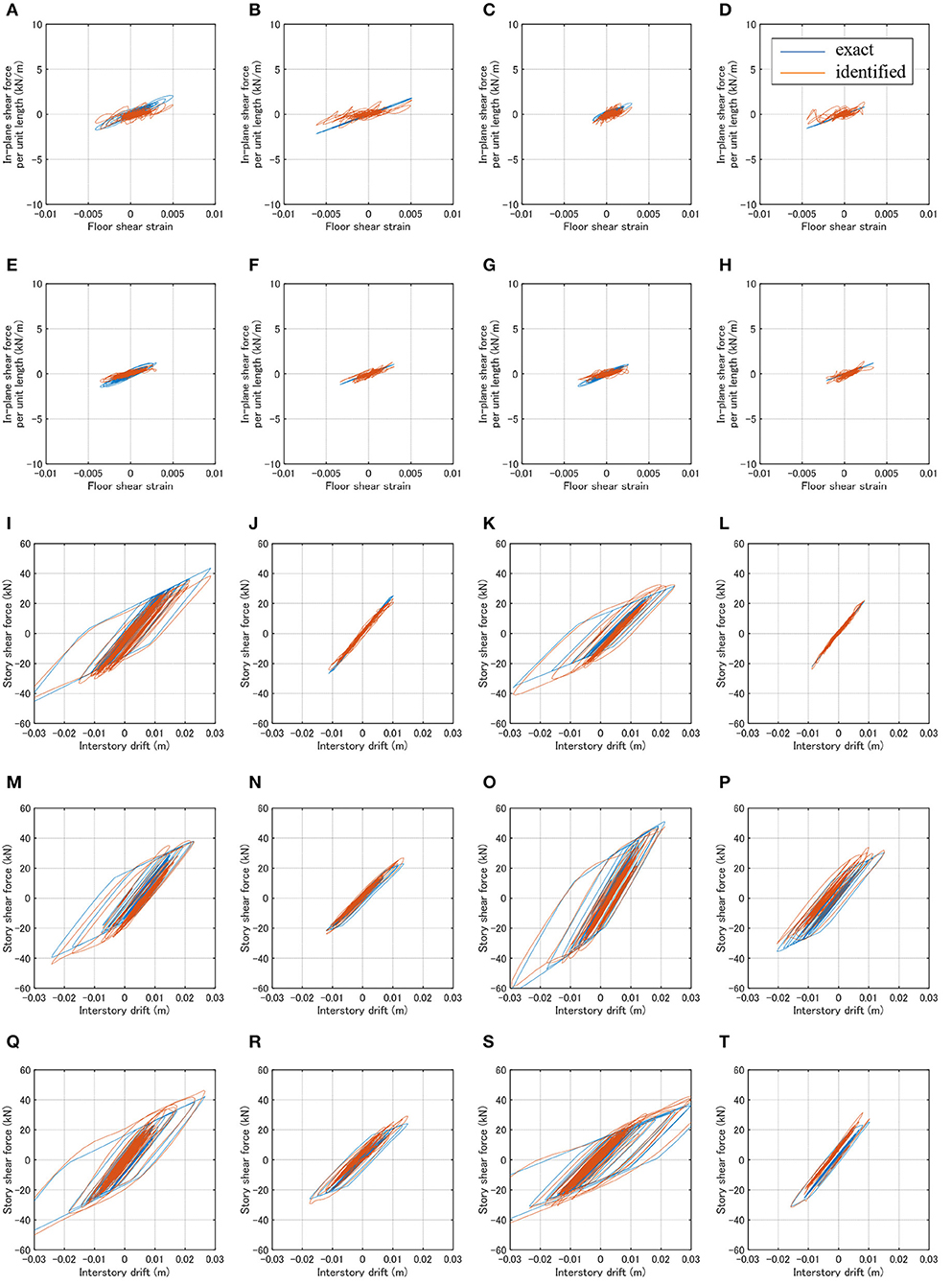
Figure 7. Identification results (El Centro 1940 NS). (A) H-frame (x1y1_1F). (B) H-frame (x1y2_1F). (C) H-frame (x2y1_1F). (D) H-frame (x2y2_1F). (E) H-frame (x1y1_2F). (F) H-frame (x1y2_2F). (G) H-frame (x2y1_2F). (H) H-frame (x2y2_2F). (I) V-frame (x1_1F). (J) V-frame (x1_2F). (K) V-frame (x2_1F). (L) V-frame (x2_2F). (M) V-frame (x3_1F). (N) V-frame (x3_2F). (O) V-frame (y1_1F). (P) V-frame (y1_2F). (Q) V-frame (y2_1F). (R) V-frame (y2_2F). (S) V-frame (y3_1F). (T) V-frame (y3_2F).
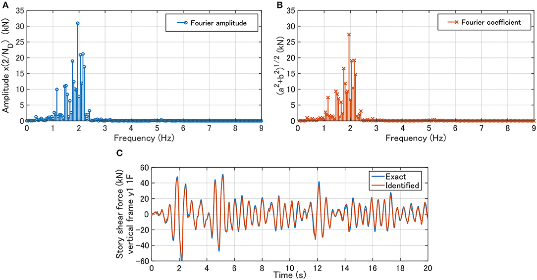
Figure 8. Verification of proposed method for story shear force of y1 frame in the first story. (A) Fourier amplitude spectrum divided by half of number of data (exact/reference value). (B) Amplitude in terms of Fourier coefficients , (identified value). (C) Comparison of time histories of between exact value and identified value.
Figure 9 presents the restoring force-shear strain hysteretic relations of horizontal frames and the restoring force-interstory drift hysteretic relations of vertical frames under Hyogoken-Nanbu 1995 (Kobe Univ. NS). Because the general properties do not differ so much from Figure 7, the results for the floors and the internal vertical frames are omitted.
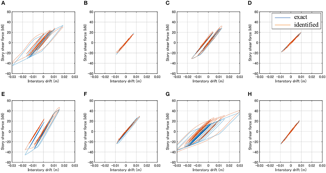
Figure 9. Identification results (Kobe Univ. NS). (A) V-frame (x1_1F). (B) V-frame (x1_2F). (C) V-frame (x3_1F). (D) V-frame (x3_2F). (E) V-frame (y1_1F). (F) V-frame (y1_2F). (G) V-frame (y3_1F). (H) V-frame (y3_2F).
It can be observed that, although some discrepancies are seen in the restoring force-shear strain hysteretic relations of horizontal frames, the predicted hysteretic restoring force characteristics corresponds fairly well to the true relations if the noise is free. A little deterioration of identification accuracy in the restoring force-shear strain hysteretic relations of horizontal frames may result from the fact that the horizontal frame identification and the vertical frame identification deal with different kinds of restoring-force characteristics and both frames experience different levels of plastic responses. In fact, the horizontal frames are in the elastic range in this case.
Influence of Noise on Identification Accuracy
It is important to investigate the influence of noise on the identification accuracy. To conduct this, independent 5% white noises as the ratio in the RMS value of the response data are added to the analyzed data. Those independent white noises are produced in the frequency range 0.075–150 (rad/s). El Centro 1940 NS is used as input in this case.
Figure 10 shows the identification results. Because of the same reason in Figure 9, the results for the internal vertical frames are omitted. It can be observed that the accuracy deterioration from the noise-free case is not clear. It seems that this is because Fourier expansion and batch processing least-squares estimation play a role as the low-pass filter. The high-frequency cut by the setting of the upper bound of frequency range in Fourier expansion enabled this low-pass filter mechanism automatically. This property is advantageous in the proposed method and it can be said that the proposed identification is robust for noise.
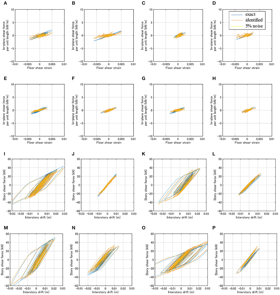
Figure 10. Identification results for case with noise (El Centro 1940 NS). (A) H-frame (x1y1_1F). (B) H-frame (x1y2_1F). (C) H-frame (x2y1_1F). (D) H-frame (x2y2_1F). (E) H-frame (x1y1_2F). (F) H-frame (x1y2_2F). (G) H-frame (x2y1_2F). (H) H-frame (x2y2_2F). (I) V-frame (x1_1F). (J) V-frame (x1_2F). (K) V-frame (x3_1F). (L) V-frame (x3_2F). (M) V-frame (y1_1F). (N) V-frame (y1_2F). (O) V-frame (y3_1F). (P) V-frame (y3_2F).
Variation of Floor Stiffness and Yield Strain
The influence of in-plane stiffness of floors on the identification accuracy is investigated here. The model parameters for the case (a), (c), (d) in Table 1 are used here, i.e., the floors except x2y2 are stiff (about 10 times stiffer than the floor x2y2). El Centro 1940 NS is input to this model. The predicted results are shown in Figure 11. As in the previous cases, the results for the internal vertical frames are omitted. It can be observed that, while the identification is possible approximately for the flexible floors, the identification is difficult for the stiff in-plane floors. This may be because the large difference in the response levels of stiff and flexible floors cause the numerical errors. The enhancement of accuracy at this point should be discussed in the future.
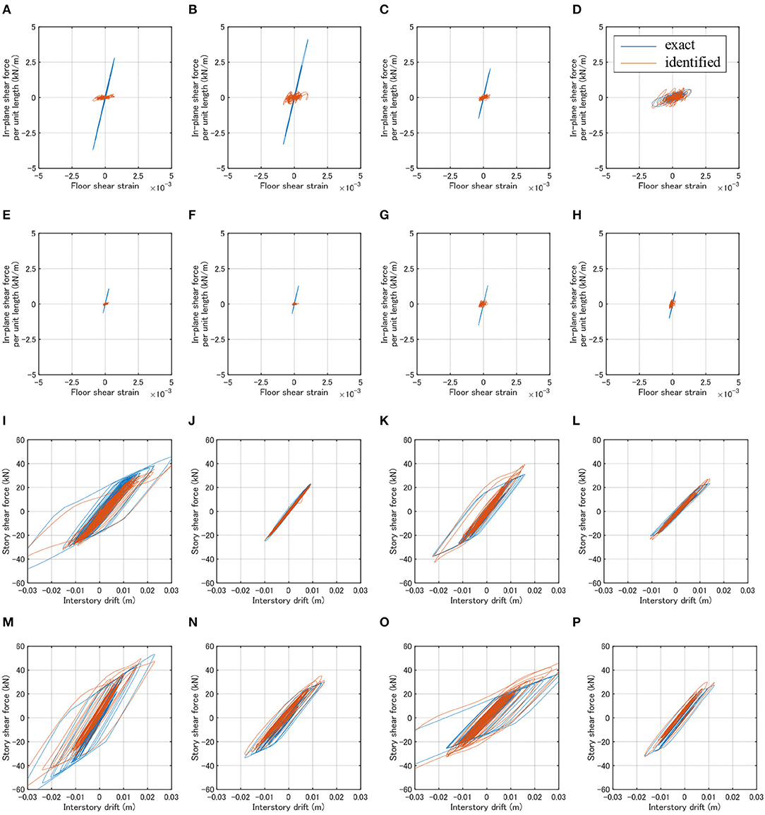
Figure 11. Identification results for case of different floor stiffness (El Centro 1940 NS). (A) H-frame (x1y1_1F). (B) H-frame (x1y2_1F). (C) H-frame (x2y1_1F). (D) H-frame (x2y2_1F). (E) H-frame (x1y1_2F). (F) H-frame (x1y2_2F). (G) H-frame (x2y1_2F). (H) H-frame (x2y2_2F). (I) V-frame (x1_1F). (J) V-frame (x1_2F). (K) V-frame (x3_1F). (L) V-frame (x3_2F). (M) V-frame (y1_1F). (N) V-frame (y1_2F). (O) V-frame (y3_1F). (P) V-frame (y3_2F).
To demonstrate the influence of the yield strain in the floors, the case of different yield strain (0.001) is analyzed and shown in Figure 12. It can be observed that, although the floors exhibit hysteretic responses, the hysteretic behaviors of the vertical frames can be identified with almost the same accuracy as in the previous cases.
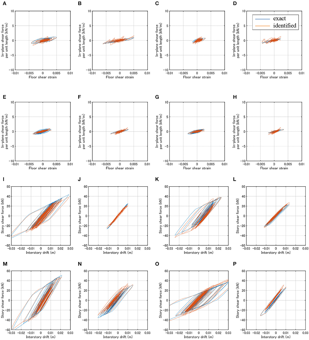
Figure 12. Identification results for case of different yield strain for floor (El Centro 1940 NS). (A) H-frame (x1y1_1F). (B) H-frame (x1y2_1F). (C) H-frame (x2y1_1F). (D) H-frame (x2y2_1F). (E) H-frame (x1y1_2F). (F) H-frame (x1y2_2F). (G) H-frame (x2y1_2F). (H) H-frame (x2y2_2F). (I) V-frame (x1_1F). (J) V-frame (x1_2F). (K) V-frame (x3_1F). (L) V-frame (x3_2F). (M) V-frame (y1_1F). (N) V-frame (y1_2F). (O) V-frame (y3_1F). (P) V-frame (y3_2F).
Conclusions
An innovative method of identification of hysteretic restoring-force characteristics has been proposed for three-dimensional (3D) building structures with in-plane flexible floors. The hysteretic restoring-force characteristics of vertical structural frames in the 3D building structure have been identified from the measured floor horizontal accelerations together with the hysteretic restoring-force characteristics of floors without the assumption of hysteresis types or a priori knowledge of restoring force characteristics. The conclusions may be summarized as follows.
(1) Fourier expansion of the time-history responses of story shear forces in vertical frames and in-plane shear forces in horizontal frames (floors) and batch processing least-squares estimation using many discrete measured data enabled the identification of hysteretic restoring-force characteristics of vertical structural frames and those of floors. A model with in-plane flexible floors has been used as a new model for physical parameter SI. The proposed method possesses an advantage that all hysteretic restoring-force characteristics of vertical structural frames and those of floors can be performed simultaneously without search iteration.
(2) Numerical simulations demonstrated that the proposed method is relatively accurate and reliable for noise-free models. Even for the model with noise, the identification accuracy does not decrease so much. It seems that this is because Fourier expansion and batch processing least-squares estimation play a role as the low-pass filter.
(3) A little deterioration of identification accuracy in the hysteretic restoring force-shear strain relations of horizontal frames occurs. This may result from the fact that the horizontal frame identification and the vertical frame identification deal with different kinds of restoring-force characteristics and both frames experience different levels of plastic responses.
(4) The influence of in-plane stiffness of floors on the identification accuracy has been investigated. It has been found that, while the identification is possible approximately for flexible floors, the identification is difficult for stiff floors.
A pinching phenomenon sometimes appears in some frame models. It seems that the present method can deal with such pinching property because the present method does not require the assumption of hysteresis types or a priori knowledge of restoring force characteristics.
Data Availability Statement
The datasets generated for this study are available on request to the corresponding author.
Author Contributions
KS formulated the problem, conducted the computation, and wrote the paper. SY conducted the computation and discussed the results. IT supervised the research and wrote the paper.
Funding
Part of the present work was supported by the Grant-in-Aid for Scientific Research (KAKENHI) of Japan Society for the Promotion of Science (Nos. 18H01584, 18J20177). This support was greatly appreciated.
Conflict of Interest
The authors declare that the research was conducted in the absence of any commercial or financial relationships that could be construed as a potential conflict of interest.
References
Agbabian, M. S., Masri, S. F., Miller, R. K., and Caughey, T. K. (1991). System identification approach to detection of structural changes. J. Eng. Mech. 117, 370–390. doi: 10.1061/(ASCE)0733-9399(1991)117:2(370)
Boller, C., Chang, F.-K., and Fujino, Y., (eds.). (2009). Encyclopedia of Structural Control and Health Monitoring, Vol. 1–5. Chichester: Wiley.
Brewick, P. T., Masri, S. F., Chassiakos, A. G., and Kosmatopoulos, E. B. (2016). A probabilistic study of the robustness of an adaptive neural estimation method for hysteretic internal forces in nonlinear MDOF systems. Probabil. Eng. Mech. 45, 140–156. doi: 10.1016/j.probengmech.2016.04.002
Cifuentes, A. O. (1984). System Identification of Hysteretic Structures, EERL 84-04. Pasadena, CA: California Institute of Technology.
Doebling, S. W., Farrar, C. R., Prime, M. B., and Shevitz, D. W. (1996). Damage Identification and Health Monitoring of Structural and Mechanical Systems From Changes in Their Vibration Characteristics, A Literature Review. Los Alamos, NM: Los Alamos National Laboratory Report, LA-13070-MS.
Fujita, K., and Takewaki, I. (2018). Stiffness identification of high-rise buildings based on statistical model-updating approach. Front. Built Environ. 4:9. doi: 10.3389/fbuil.2018.00009
Hart, G. C., and Yao, J. T. P. (1977). System identification in structural dynamics. J. Eng. Mech. Div. 103, 1089–1104.
Ikhouance, F., and Rodellar, J. (2007). Systems With Hysteresis: Analysis, Identification and Control Using Bouc-Wen Model. Chichester: John Wiley & Sons Ltd.
Kitada, Y. (1998). Identification of nonlinear structural dynamic systems using wavelets. J. Eng. Mech. 124, 1059–1066. doi: 10.1061/(ASCE)0733-9399(1998)124:10(1059)
Kitada, Y. (2000). Identification of nonlinear structural systems via wavelet transformation (Ph.D. thesis). Kyoto University, Kyoto.
Kitada, Y., Nakamura, Y., Takewaki, I., and Uetani, K. (2000). Mechanical modelling of high-damping rubber dampers using nonlinear system identification. J. Struct Construct. Eng. 531, 63–70. doi: 10.3130/aijs.65.63_2
Leontaritis, I. J., and Billings, S. A. (1985). Input-output parametric models for nonlinear systems. Int. J. Control 41, 303–344. doi: 10.1080/0020718508961129
Li, S. J., Suzuki, Y., and Noori, M. (2004b). Improvement of parameter estimation for non-linear hysteretic systems with slip by a fast Bayesian bootstrap filter. Int. J. Non Linear Mech. 39, 1435–1445. doi: 10.1016/j.ijnonlinmec.2004.02.005
Li, S. J., Yu, H., and Suzuki, Y. (2004a). Identification of non-linear hysteretic systems with slip. Comput. Struct. 82, 157–165. doi: 10.1016/j.compstruc.2003.10.005
Loh, C.-H., and Chung, S.-T. (1993). A three-stage identification approach for hysteretic systems. Earthq. Eng. Struct. Dyn. 22, 129–150. doi: 10.1002/eqe.4290220204
Masri, S. F., Chassiakos, A. G., and Caughey, T. K. (1993). Identification of nonlinear dynamic systems using neural networks, J. Appl. Mech. 60, 123–133. doi: 10.1115/1.2900734
Masri, S. F., Miller, R. K., Saud, A. F., and Caughey, T. K. (1987). Identification of nonlinear vibrating structures (Part I, Part II). J. Appl. Mech. 54, 918–929. doi: 10.1115/1.3173139
Nabeshima, K., and Takewaki, I. (2017). Frequency-domain physical-parameter system identification of building structures with stiffness eccentricity. Front. Built Environ. 3:71. doi: 10.3389/fbuil.2017.00071
Nagarajaiah, S., and Basu, B. (2009). Output only modal identification and structural damage detection using time frequency & wavelet techniques. Earthq. Eng. Eng. Vib. 8, 583–605. doi: 10.1007/s11803-009-9120-6
Nakamura, M., and Yasui, Y. (1999). Damage evaluation of a steel structure subjected to strong earthquake motion based on ambient vibration measurements. J. Struct. Construct. Eng. 517, 61–68. doi: 10.3130/aijs.64.61_1
Omrani, R., Hudson, R. E., and Taciroglu, E. (2012). Story-by-story estimation of the stiffness parameters of laterally-torsionally coupled buildings using forced or ambient vibration data: I. Formulation and verification. Earthq. Eng. Struct. Dyn. 41, 1609–1634. doi: 10.1002/eqe.1192
Pelliciari, M., Marano, G. C., Cuoghi, T., Briseghella, B., Lavorato, D., and Tarantino, A. M. (2018). Parameter identification of degrading and pinched hysteretic systems using a modified Bouc-Wen model. Struct. Infrastruct. Eng. 14, 1573–1585. doi: 10.1080/15732479.2018.1469652
Saadat, S., Buckner, G. D., Furukawa, T., and Noori, M. N. (2004). An intelligent parameter varying (IPV) approach for non-linear system identification of base excited structures. Int. J. Non Linear Mech. 39, 993–1004. doi: 10.1016/S0020-7462(03)00091-X
Shintani, K., Yoshitomi, S., Fujita, K., and Takewaki, I. (2019). Stiffness and damping identification for asymmetric building frame with in-plane flexible floors. Front. Built Environ. 5:103. doi: 10.3389/fbuil.2019.00103
Shintani, K., Yoshitomi, S., and Takewaki, I. (2017). Direct linear system identification method for multi-story three-dimensional building structure with general eccentricity. Front. Built Environ. 3:17. doi: 10.3389/fbuil.2017.00017
Takewaki, I., and Nakamura, M. (2000). Stiffness-damping simultaneous identification using limited earthquake records. Earthq. Eng. Struct. Dyn. 29, 1219–1238. doi: 10.1002/1096-9845(200008)29:8<1219::AID-EQE968>3.0.CO;2-X
Takewaki, I., and Nakamura, M. (2005). Stiffness-damping simultaneous identification under limited observation. J. Eng. Mech. 131, 1027–1035. doi: 10.1061/(ASCE)0733-9399(2005)131:10(1027)
Takewaki, I., Nakamura, M., and Yoshitomi, S. (2011). System Identification for Structural Health Monitoring. WIT Press.
Tasbihgoo, F., Caffrey, J. P., and Masri, S. F. (2007). Development of data-based model-free representation of non-conservative dissipative systems. Int. J. Non Linear Mech. 42, 99–117. doi: 10.1016/j.ijnonlinmec.2006.10.021
Toussi, S., and Yao, J. T. P. (1983). Hysteresis identification of existing structures. J. Eng. Mech. 109, 1189–1202. doi: 10.1061/(ASCE)0733-9399(1983)109:5(1189)
Udwadia, F. E., Sharma, D. K., and Shah, P. C. (1978). Uniqueness of damping and stiffness distributions in the identification of soil and structural systems. J. Applied Mech. 45, 181–187. doi: 10.1115/1.3424224
Worden, K., and Manson, G. (2010). “On the identification of hysteretic systems, part I: an extended evolutionary scheme,” in Proceedings of the IMAC-XXVIII (Jacksonville, FL).
Keywords: system identification, model-free identification, restoring-force characteristic, torsional response, in-plane flexible floor, batch processing least-squares method, Fourier expansion
Citation: Shintani K, Yoshitomi S and Takewaki I (2020) Model-Free Identification of Hysteretic Restoring-Force Characteristic of Multi-Plane and Multi-Story Frame Model With In-Plane Flexible Floor. Front. Built Environ. 6:48. doi: 10.3389/fbuil.2020.00048
Received: 28 January 2020; Accepted: 24 March 2020;
Published: 21 April 2020.
Edited by:
Cristiano Loss, University of British Columbia, CanadaReviewed by:
George C. Tsiatas, University of Patras, GreeceMohammad Noori, California Polytechnic State University, United States
Copyright © 2020 Shintani, Yoshitomi and Takewaki. This is an open-access article distributed under the terms of the Creative Commons Attribution License (CC BY). The use, distribution or reproduction in other forums is permitted, provided the original author(s) and the copyright owner(s) are credited and that the original publication in this journal is cited, in accordance with accepted academic practice. No use, distribution or reproduction is permitted which does not comply with these terms.
*Correspondence: Izuru Takewaki, takewaki@archi.kyoto-u.ac.jp