Dimensional Scaling and Failure Pattern of the Tensile Properties of Angle-Ply Thermoplastic Composites of Twaron Fiber/Polypropylene
 Cesar Martin-Barrera
  Pedro I. Gonzalez-Chi
- Centro de Investigación Científica de Yucatán, Mérida, Mexico
Thermoplastic multilayer composites with different fiber orientations were prepared with polypropylene and aramid fibers as reinforcing material. The prepregs were prepared in a continuous impregnation system using the dry powder method in a fluidized bed. The specimens were laminated by compression molding, tensile tested, and their fracture area was analyzed by microscopy. The mechanical performance of the laminates was influenced by the fiber orientation at the different layers. The fibers at 0° conferred high stiffness to the composite, limiting the maximum deformation and promoting failure. The laminates with 0° layers showed a fragile and sudden fracture oriented at 90° to the aplied load, even with low fiber content. The plies oriented at ± 45° balanced the stress and contributed to higher levels of deformation during the test due to fiber rotation toward the loading direction, also, no post-yield stiffening was found as in thermoset composites due to the ductile nature of the thermoplastic matrix; these layers limited the crack propagation in the transverse direction, canceling the in-plane shear stress. The fibers at 90° acted as filler due to poor interface and did not contribute to the improvement of the composite mechanical performance. The evidence shows no delamination in the materials due to the tenacious nature of the thermoplastic matrix, neither saw-toothed or plateau region was found in the stress-strain curves in contrast to thermoset laminates.
Introduction
Fiber reinforced thermoset composites are well-known to possess high stiffness and strength. However, they are limited by linear elasticity and often exhibit brittle, sudden, and catastrophic failure, which occurs without warning. Thermoplastic composites reinforced with continuous fiber are receiving much attention and growing interest in the industry for lightweight applications owing to many attractive advantages in comparison to composites based on thermoset matrices; their advantages are mainly based on the inherent properties of thermoplastic polymers used, such as fracture toughness and damage tolerance (higher strain to failure), recyclability, clean processability (shaping prior to consolidation and the ability to be reshaped), faster manufacturing and long shelf life (Gonzalez-Chi et al., 2004; Hufenbach et al., 2011; Hassan et al., 2013; Fuller and Wisnom, 2015a; Shan-Shan et al., 2018). On the other hand, the joint between plies in thermoplastic laminates is formed by fusion, consequently there is no interphase, thus failure by delamination is not possible (common failure mechanism of thermoset laminates). However, the present application areas of these thermoplastic composites is mostly limited to secondary and semi-structural parts; to make thermoplastic composites attractive for primary advanced structures, the scaling issues of the mechanical performance have to be solved and the performance/cost ratio has to be improved.
The matrix of thermoplastic composites has a high viscosity at processing temperatures, within 500–5,000 Pa s (Bernhardsson and Shishoo, 2000), consequently, it is difficult to achieve an uniform distribution of fiber into the thermoplastic matrix, affecting the final quality of the composite (Tufail, 2007). The matrix should flow distances as short as possible to totally wet the fibers during melt impregnation of the prepreg. One convenient method proposed to get thermoplastic prepreg composites is the powder method: the reinforcing fiber yarn is continuously coated with the matrix powder and then consolidated by compression molding (González-Chi and Ramos-Torres, 2007).
The capacity to design angle-ply laminate properties through judicious choice of fiber orientation, stacking sequence and fiber volume fraction make advanced materials attractive for specific applications. A vast research work has been done to explain mechanical behavior and failure mechanism of angle-ply laminate composites based on thermosetting matrix. The structural analysis of these anisotropic multilayered composites is centered on the influence of the fiber orientation of the different layers on the composite's mechanical properties (Pagano and Pipes, 1971; Schijve et al., 1979; Ishai et al., 1988; Sutherland et al., 1999; Fuller and Wisnom, 2015a).
Also, the influence of the stacking sequence on the failure process of angle-ply laminates has been extensively studied. Taubert et al. (2015) studied the influence of stacking sequence and ply stiffness reduction on the non-linear behavior of carbon/epoxy composites, and found that the layup dependency of the non-linear laminate response is a consequence of the damage evolution during the tensile test and the fiber reorientation (up to 8°) in the ±45° angle ply laminates, causing an increase of the laminate stiffness at the loading direction.
Herakovich (1982) studied the failure of graphite-epoxy angle-ply laminates with fiber orientations at 10°, 30°, and 45° at two different stacking sequences [(±θ)2]s and [(+θ)2/(–θ)2]s. Herakovich's experimental results showed two different failure mechanisms for angle-ply laminates: the pull-out of the inner layer from the outer layers due to transverse cracks and delamination without fiber breakage, and the failure of a single crack across the width of the laminate parallel to fiber direction of the outer layers. Therefore, Herakovich's observations encompass three basic failure modes i.e., transverse cracking, delamination, and fiber breakage. Herakovich's theoretical analyses showed that by increasing the thickness of individual layers, the interlaminar shear stress can be increased, which will lead to easier occurrence of inner layer pull-out failure mechanism.
Typically, the transverse microcracking through the thickness of the ply occurs as first-ply failure. The thin-ply method can be used to improve the pseudo-ductility behavior of laminate composites (Czél et al., 2016); the failure mode transformation from delamination to fiber break brings a different pseudo-ductility response; ply thickness plays a key role in controlling composite mechanical properties: the thinner the ply the better the properties (First Ply Failure Theory; Kim and Soni, 1984).
Fuller and Wisnom (2015a) investigated carbon-epoxy multilayer laminates at [(±θ)5]s with several angles between 15 and 45°. Highly non-linear stress–strain behavior can be achieved with angle-ply laminates, whilst suppressing the damage mechanisms that normally cause premature failure. They showed that, using thin plies, delamination is suppressed for all angles allowing considerable pseudo-ductile strains to develop. Significant fiber rotations take place, permitted by matrix plasticity, leading to a post-yield stiffening of the laminate, as the fibers reorient toward the direction of loading. They also used an analytical modeling method that incorporates matrix plasticity and reorientation of the fibers into a classical laminate analysis to predict the in-plane response of thin ply angle-ply laminates; the method successfully predicted the non-linear behavior of [±θ5]s laminates with angle-ply between 15 and 45° (Fuller and Wisnom, 2015b; Wisnom, 2016).
Compared to thermoset composites, some research work has been done on multilayer thermoplastic composites; nevertheless, several research areas still need better knowledge development. Pulungan et al. (2017) used unidirectional tapes from SABIC Innovative Plastics to produce [90]8 glass fiber/polypropylene thermoplastic laminates, they proposed a micromechanical approach to predict damage mechanisms and their interactions in laminates under transverse tension using 3D finite element model. They studied the microscopic failure mechanisms and their effect on the mesoscale response and found that fiber-matrix interfacial strength affects the stiffness and the strength of the composite significantly. The higher the interface strength, the stiffer and stronger the composite will be and the interfacial fracture energy controls the ductility of the composite. The higher the interface energy, the more ductile the composite will be.
Kellas and Morton (1992) investigated the effect of specimen size upon the response and strength of ±45° angle-ply laminates for two graphite fiber reinforced plastic systems; the first with epoxy based system (thermoset) and the second with PEEK based system (thermoplastic). For the thermoset system two generic ±45° lay-ups were studied; ply level scaling method (+/−)2s (blocked plies) and the sublaminate level scaling method (+45°/−45°)2ns (distributed plies), where n = l, 2, 3, and 4. In the case of the thermoplastic system only the lay-up with distributed plies was investigated; It was shown that the stress/strain response and the ultimate strength of these angle-ply laminates depends on the laminate thickness and the type of generic lay-up (whether the plies are blocked or distributed).
The epoxy-based specimens with blocked plies exhibited a brittle-like stress/strain response, their ultimate strength and strain at failure increased with decreasing blocked ply thickness, specimens with distributed plies, however, exhibited a ductile like stress/strain response and the ultimate strength and strain at failure increased with the specimen thickness. The PEEK matrix specimens exhibited a more ductile stress/strain response, having a lower initial longitudinal stiffness and failing at higher strains. In the case of the baseline (8-ply) specimens, the difference in the strain at failure between the epoxy and the PEEK matrix specimens was ~15%.
Martin-Barrera and Gonzalez-Chi (2012) tested [(±45)]S Twaron fiber/polypropylene laminate composites, they studied the scaling effects on the mechanical performance under tension. For thickness scaled composites, no significant size effect was observed, but the results showed a clear influence for the in-plane and volume (3D) scaled composites; the increasing size scale made them more ductile and their failure mechanism was governed by interfacial failure.
The present study addresses the effects of the dimensional scaling and continuous fiber orientation on the tensile properties of thermoplastic composites of Twaron fiber/polypropylene. The failure pattern of these materials was studied and related to the composite structure and performance.
Materials and Methods
Materials
The materials used in the present study were polypropylene PP30 (PEMEX) as matrix and aramid fibers Twaron 2200/1610 (Teijin) supplied as a yarn with 1,000 filaments of 12 μm diameter and specific weight of 1.45 g/cm3. Table 1 shows the mechanical properties of these materials.
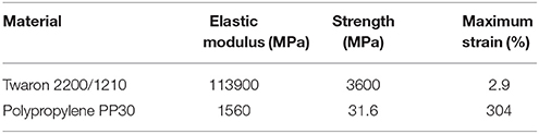
Table 1. Mechanical properties of Twaron fiber and Polypropylene.
Methodology
The polypropylene was first ground and sieved through a Tyler # 60 mesh. The prepregs were prepared in a continuous impregnation system based on the dry powder impregnation method: the fiber yarn passed through a gas-solid fluidized bed to be pre-impregnated with polypropylene powder (Martín-Barrera, 2004). Immediately after, the pre-impregnated material was heated at 180°C to consolidate the powder on the fiber surface; the composite prepregs was collected at room temperature in a bobbin before the molding process. The mold used produces a laminate integrated with tensile test taps; the prepregs were cut and fitted into the 250 × 250 mm mold; each layer was stacked to get the different laminates in accordance with Figure 1. The tap area of the mold was filled with PP powder, Tyler # 60 mesh; the laminate and the taps were compression molded simultaneously at 230°C for 30 min with no pressure and for a further 3 min at 40 KPa, the mold was then cooled gradually for 15 min to room temperature. This molding process generates a laminate with a nominal thickness of 0.162 mm per layer and a fiber volume fraction between 6 and 10; the powder impregnation method has been preliminary tested to prepare thermoplastic laminates with an interval of fiber volume fraction between 6 and 28 (González-Chi and Ramos-Torres, 2007). Over this interval, the PP is unable to efficiently wet the reinforcing fiber. The present work was done with the lower volume fraction to ensure that the matrix was able to fully wet the Twaron fiber, and no misleading results were found during the failure process.
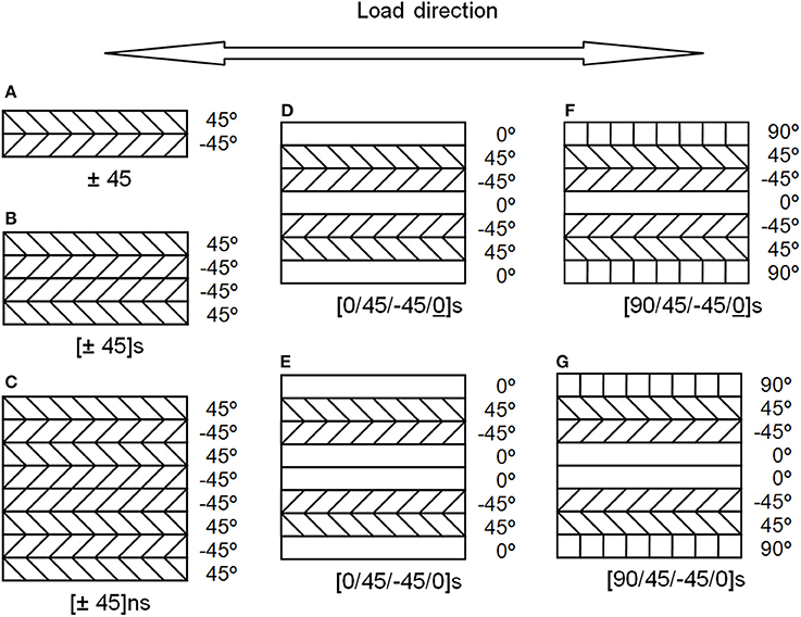
Figure 1. Configuration of the molded composites, (A) [±45], (B) [±45]s, (C) [±45]2s, (D) [0/±45/0]s, (E) [0/±45/0]s, (F) [90/±45/0]s, and (G) [90/±45/0]s.
Laminates B and C (Figures 1B,C) are the dimensional scaling in thickness of laminate A +45°/−45° (Figure 1A). The sublaminate level scaling method was used.
Laminates D and E (Figures 1D,E) have fibers oriented 0° at their central and external layers. Laminate D has only one 0° layer in the center and laminate E has two 0° layers.
Laminates F and G (Figures 1F,G) have a configuration similar to laminates D and E respectively, but their external layers have fibers oriented at 90°.
Laminates D and F are symmetrical laminates and laminates E and G are symmetrical and balanced laminates.
Microscopy
A Leica DMLM optical microscope with polarized light was used to monitor the quality of the polished edges of the specimens prior the tensile test in order to ensure a well-finishing edge surface. A Motic DM143 stereoscopic microscope was used to observe the raw in-plane fractured zone of the specimens (after the tensile test) to analyze the failure mechanism caused by the tensile test.
Tensile Test
The tensile test was performed with the (ASTM D3039/D3039M-17, 2017) for tensile properties of polymer matrix composites. The tensile specimens were cut from each laminate with a band saw, and the edges were polished to eliminate any irregularity. Figure 2 shows the tensile specimen geometry and dimensions according to ASTM. The tensile tests was performed in a Shimadzu universal testing machine (model AG-1) equipped with a 50 KN load cell. The crosshead speed was set to get a strain rate of 8.33 × 10⁻³ min−1; an extensometer (Shimadzu SG25-10) was fitted to each specimen to measure the tensile strain. The tensile load and strain were simultaneously monitored to estimate tensile strength and Young's modulus (E11) of the laminate specimens. Six specimens were tested per laminate type.
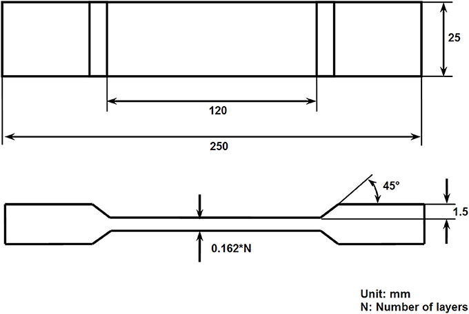
Figure 2. Dimensions of the tensile test specimens.
Soxhlet Extraction
The tested tensile specimens were subjected to Soxhlet extraction to measure the fiber volume fraction of the laminates (ASTM C613-14, 2014). Sections of 25 × 45 mm were cut from the tensile tested laminates, taking care not to select the fractured zone of the specimens. The samples were dried to a constant weight by removing moisture in a convection oven. The PP matrix was removed from the samples with a Soxhlet extractor using xylene (138°C), with a reflux frequency of 3 reflux changes per hour. After removing the PP, the remaining fiber was dried to constant weight. The fiber volume fractions of the laminates were calculated from the weight of the dry samples and the fiber specific weight (1.45 g/cm3).
Results
Microscopy
Optical Microscopy
The polished edges of the specimens were analyzed by optical microscopy prior the tensile test, no irregularities caused by the cutting process were observed. Figure 3A, shows the transversal section of the +45° and −45° fiber orientation in the internal structure of the 8 layers of laminate C. Figure 3B shows the transversal section of laminate E with 8 layers at +45°, −45° and 0°.
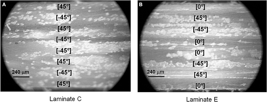
Figure 3. Micrographs of the sanded edges, (A) laminate C and (B) laminate E.
Stereoscopic Microscopy
The in-plane surface of the fractured section of the tested specimens was observed with a stereoscopic microscope. The images (Figures 4, 5) show a different failure mechanism between the composites with only ±45° layers (laminates A, B, and C) and those containing layers oriented at 0° (laminates D, E, F, and G); crack propagation was influenced by the orientation of the fibers. The fracture of laminates A, B, and C propagated mainly along the fiber direction (+45° and −45°), all the laminates show pull-out fiber and the fiber-matrix interface is the weakest part of the composite (poor interfacial adhesion). The interfacial cracks of the laminates with ±45° layers branch off in a zig-zag pattern, which delays the failure of the composite and promotes high levels of deformation due to the scissoring effect between layers. No evidence of delamination was found.
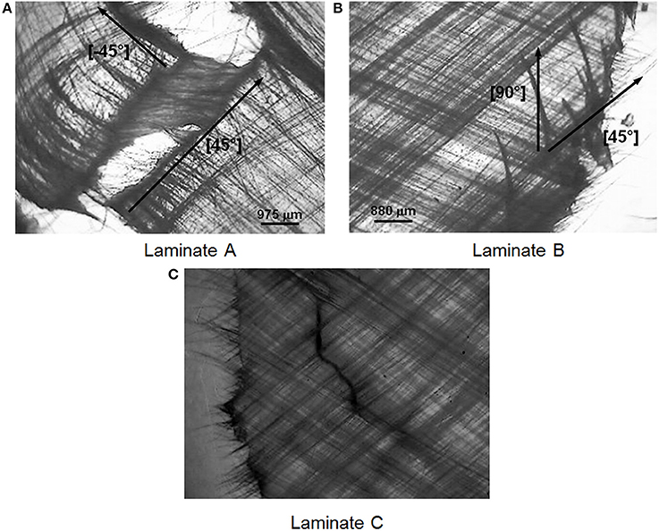
Figure 4. Fracture area of the tested tensile specimens (stereoscopic micrographs), (A) laminate A, (B) laminate B, and (C) laminate C.
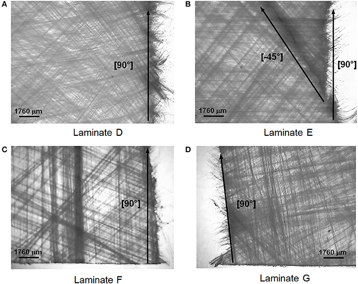
Figure 5. Fracture area of tested tensile specimens (stereoscopic micrographs), (A) laminates D, (B) laminate E, (C) laminate F and (D) laminate G.
The laminates D, E, F, and G had 0° layers and showed a fragile and sudden fracture oriented 90° to the aplied load (Figure 5). The 0° layers increased the composite stiffness and led to a fragile fracture behavior controled by the fracture of the fibers at 0°. Laminates D and E (Figures 5A,B) show also fissures at the ±45° layers, the energy from the failure of the fibers at 0° was used to interfacial failure of the fibers at the ±45° layers. On the other hand, at laminates F and G (Figures 5C,D) the failure of the fibers at 0° drove crack propagation along the fibers at 90° due to poor interfacial adhesion and the final composite failure fractured oriented at 90° direction.
Soxhlet Extraction
The fiber volume fraction of the different laminates is shown in Table 2; the laminate fiber content showed a variation most probably caused by the partial loss of the polypropylene during the molding process (the matrix can flow out of the mold). The variation of fiber volume fraction of the composites affects their mechanical properties and must be taken into account when analyzing the results.
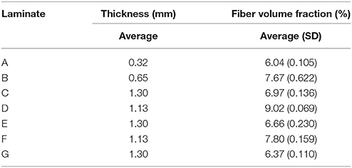
Table 2. Fiber volume fraction of the laminates.
Mechanical Properties
The tensile properties (elastic modulus, strength, and maximum strain) of the tested laminates are shown in Table 3. In contrast to the thermosetting laminates, the stress-strain curves do not exhibit a plateau region.
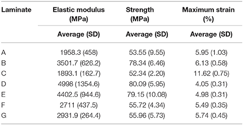
Table 3. Tensile properties of laminates Twaron/PP.
The absolute value of these mechanical properties are influenced by the fiber volume fraction on each tested composite; in order to compare the mechanical behavior of the different laminates, their tensile properties (modulus and strength) where divided by their respective fiber volume fraction to normalize the results (reduced mechanical properties) (Martin-Barrera and Gonzalez-Chi, 2012).
Laminates A, B, and C
These laminates represent a dimensional scaling in thickness, incrementing the layer number using the sublaminate level scaling method, the in-plane dimensions (x-y plane) were preserved; laminate A is symmetric, laminates B, and C are symmetric and balanced. Figure 6 shows the typical stress-strain curves of the tested laminates and Figure 7 shows the reduced mechanical properties of laminates A, B, and C.
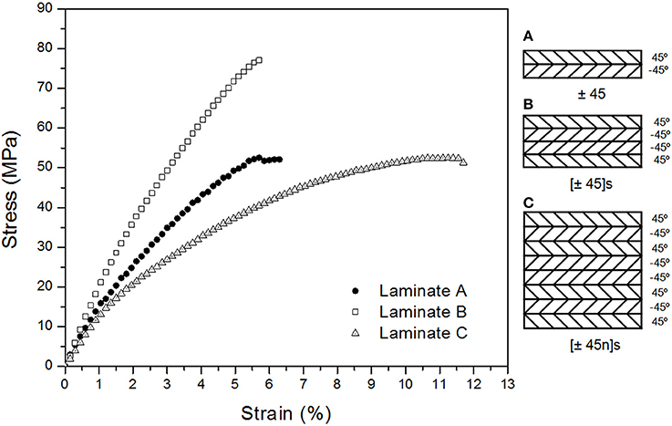
Figure 6. Stress-strain curves of laminates (A–C).
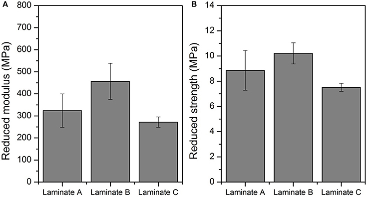
Figure 7. Reduced mechanical properties of laminates A, B, and C, (A) Reduced modulus and (B) Reduced strength.
The unbalanced stress of laminate A promoted low levels of stress-strain with a premature fracture. The balanced laminate B presented better properties than laminate A, with higher stiffness and consequently lower strain (Figures 6, 7). Laminate C performed more ductile than A and B; as the number of layers increased, higher levels of deformation were reached due to the fiber reorientation into the ductile matrix. The external layer of a laminate has a completely different mechanical performance due to the lack of a neighboring layer; the influence of these external layers on the mechanical performance of the full laminate becomes less important as the number of layers is increased, this is why more deformation was reached by the eight layer laminate.
Laminates D and E
Figure 8 shows the typical stress-strain curves from laminates D and E; as can be seen, the composites failed when the material reached over 3% of deformation, which approximately corresponds to the maximum strain of the Twaron fiber (Table 1). The composite mechanical performance of both laminates was controlled by the 0° layers, the microcracks began to appear at the 0° layers (mainly at the external ones) when the composite reached 3% of deformation, the crack propagates to the neighboring ±45° layers until full fracture of the specimen.
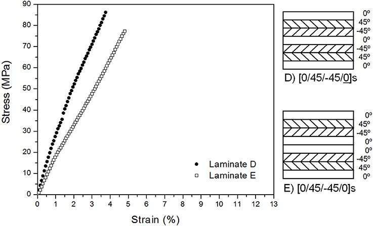
Figure 8. Stress-strain curves of laminates D and E.
Figure 9 shows the reduced mechanical properties (modulus and strength) of laminates D and E; the reduced modulus and strength of laminate E is higher than laminate D due to the extra 0° layer. Laminates D and E showed a higher stiffness compared to laminates A, B, and C due to their 0° layers; however, the failure of the 0° fibers caused the propagation of the cracks through the interface of the ±45 fibers, reducing their maximum deformation.
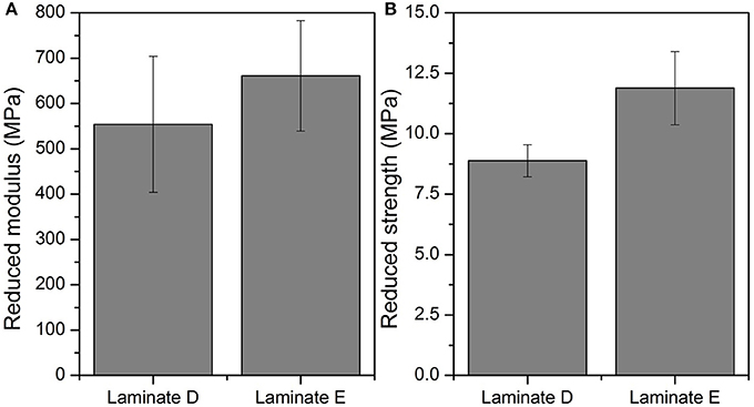
Figure 9. Reduced mechanical properties of laminates D and E, (A) Reduced modulus and (B) Reduced strength.
Laminates F and G
Figure 10 shows the typical stress-strain curves from laminates F and G; these composites failed when the material reached over 3% of deformation (Table 1) which corresponds to the failure strain of Twaron fibers.
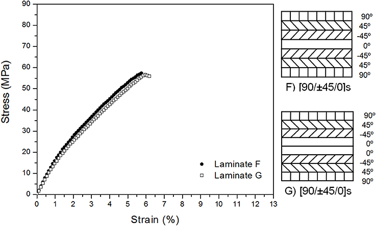
Figure 10. Stress-strain curves of laminates F and G.
Figure 11 shows the reduced mechanical properties of laminates F and G; The 90° external layers of these laminates should reduce the possibility of premature formation of in-plane fissures, nevertheless, the weak interface between the Twaron fiber and the polypropylene made them the less resistant layers, consequently affecting the laminate; the applied load was supported only by the ±45 and 0° layers.
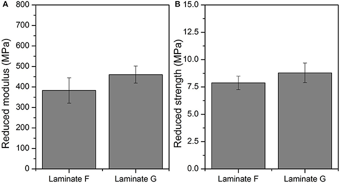
Figure 11. Reduced mechanical properties of laminates F and G, (A) Reduced modulus and (B) Reduced strength.
The reduced modulus and strength of laminate G shows a tendency to increase, the extra layer at 0° conferred better mechanical properties to laminate G, in comparison with laminate F. However, the premature fracture caused by the propagation of the cracks initiated at the 0° fibers and the interfacial fracture at the outer layers led to a lower mechanical performance when compared with laminates D and E.
Conclusions
The present study explains the deformation and failure processes of thermoplastic composite laminates subjected to tensile testing; the ductility of the PP allowed the composite deformation and the fiber flow on the applied load direction and the final fracture was controlled by the fibers interface failure.
The force balance of the in-plane shear stress at the ±45° layers caused the tendency of the fiber to align to the applied load, increasing the material deformation (pseudo-ductile behavior), but this fiber reorientation did not conferred post-yield stiffening in the laminate as occurs with thermosetting laminates, due to the ductile nature of the thermoplastic, and the branch off in a zig-zag pattern of the interfacial cracks of the laminates with ±45° layers, given that the fiber-matrix interface is the weakest part of the composite.
Laminates D and E had the highest strength due to their 0° layer, even with low content of fiber showed a fragile fracture oriented at 90° to the aplied load; the failure was promoted when the composite deformation surpassed 3% deformation, which corresponds to the maximum strain of the 0° Twaron fibers which began to fail generating cracks that propagated to the interface of the neighboring ±45° layers until full fracture of the material.
The laminates F and G with 90° layers reduced the strength of these composites because they acted as stress concentration areas: the failure of the 0° fibers led to the fiber-matrix interface at the laminate surface; the applied load was only supported by the 45° and 0° layers.
Tensile test results show no delamination in the materials mainly because the manufacture process by matrix fusion and compression molding avoids the interphase formation between layers and the stress-strain curves do not exhibit a plateau region due to the matrix tenacity. The microcrack formation and its subsequent propagation occurred due to interfacial failure allowing the crack to propagate along the fibers, failure occurred when several cracks joined. It was evident that the weakest part of the material is the interface, consequently pull-out fibers were found in all composites.
Author Contributions
PG-C: Conception of the work and director of the project, giving the final approval of the version to be published; GS-M: Data acquisition, interpretation of data for the work, ensuring that questions related to the accuracy or integrity of any part of the work are appropriately investigated and resolved; CM-B: Drafting, revision and analysis, revising the intellectual content of the study.
Conflict of Interest Statement
The authors declare that the research was conducted in the absence of any commercial or financial relationships that could be construed as a potential conflict of interest.
The reviewer, MS, and handling Editor declared their shared affiliation.
References
ASTM C613-14 (2014). Standard Test Method for Constituent Content of Composite Prepreg by Soxhlet Extraction. ASTM International, West Conshohocken, PA. Available online at: www.astm.org
ASTM D3039/D3039M-17 (2017). Standard Test Method for Tensile Properties of Polymer Matrix Composite Materials. ASTM International, West Conshohocken, PA. Available online at: www.astm.org
Bernhardsson, J., and Shishoo, R. (2000). Effect of processing parameters on consolidation quality of GF/PP commingled yarn based composites. J. Thermoplast. Compos. Mater. 13, 292–313. doi: 10.1177/089270570001300403
Czél, G., Jalalvand, M., and Wisnom, M. R. (2016). Design and characterization of advanced pseudo-ductile unidirectional thin-ply carbon/epoxy–glass/epoxy hybrid composites. Compos. Struct. 143, 362–370. doi: 10.1016/j.compstruct.2016.02.010
Fuller, J. D., and Wisnom, M. R. (2015a). Pseudo-ductility and damage suppression in thin ply CFRP angle-ply laminates. Compos. Part A 69, 64–71. doi: 10.1016/j.compositesa.2014.11.004
Fuller, J. D., and Wisnom, M. R. (2015b). Exploration of the potential for pseudo-ductility in thin ply CFRP angle-ply laminates via an analytical method. Compos. Sci. Technol. 112, 8–15. doi: 10.1016/j.compscitech.2015.02.019
González-Chi, P. I., and Ramos-Torres, W. (2007). Preparation and characterization of thermoplastic composite materials reinforced with engineering fibers. Rev. Mex. Ingeniería Química. 6, 51–58. Available online at: http://www.redalyc.org/articulo.oa?id=62060107
Gonzalez-Chi, P. I., May-Hernandez, L. H., and Carrillo-Baeza, J. G. (2004). Polypropylene composites unidirectionally reinforced with polyester fibers. J. Compos. Mater. 38, 1521–1153. doi: 10.1177/0021998304043754
Hassan, M., Dessouky, E. L., and Carl, A. L. (2013). Ultra-lightweight carbon fibre/thermoplastic composite material using spread tow technology. Compos. B 50, 91–97. doi: 10.1016/j.compositesb.2013.01.026
Herakovich, C. T. (1982). Influence of layer thickness on the strength of angle-ply laminates. J. Compos. Mater. 16, 216–227. doi: 10.1177/002199838201600305
Hufenbach, W., Böhm, R., Thieme, M., Winkler, A., Mäder, E., Rausch, J., et al. (2011). Polypropylene/glass fibre 3D-textile reinforced composites for automotive applications. Mater. Design 32, 1468–1476. doi: 10.1016/j.matdes.2010.08.049
Ishai, O., Rosenthal, H., Sela, N., and Drukker, E. (1988). Effect of selective adhesive interleaving on interlaminar fracture toughness of graphite/epoxy composite laminates. Compos. A 19, 49–54. doi: 10.1016/0010-4361(88)90543-5
Kellas, S., and Morton, J. (1992). NASA Contracter Report 4423-Scaling Effects in Angle-Ply Laminates. Sci. Tech. Inform. Prog. 1–55.
Kim, R. Y., and Soni, S. R. (1984). Experimental and analytical studies on the onset of delamination in laminated composites. J. Compos. Mater. 18, 70–80. doi: 10.1177/002199838401800106
Martín-Barrera, C. (2004). Design and Construction of a System for Impregnation of Unidirectional Composite Materials., Thesis, Instituto Tecnológico de Mérida, México, 2004.
Martin-Barrera, C., and Gonzalez-Chi, P. I. (2012). Scaling effects on the mechanical performance of symmetrical and balanced thermoplastic laminates. Polym. Test. 31, 1053–1061. doi: 10.1016/j.polymertesting.2012.07.013
Pagano, N. J., and Pipes, R. B. (1971). “The influence of stacking sequence on laminate strength”., Mech. of Compos. Mater. 34, 246–254. doi: 10.1007/978-94-017-2233-9_20
Pulungan, D., Lubineau, G., Yudhanto, A., Yaldiz, R., and Schijve, W. (2017). Identifying design parameters controlling damage behaviors of continuous fiber-reinforced thermoplastic composites using micromechanics as avirtual testing tool. Int. Solids Struct. 117, 177–190. doi: 10.1016/j.ijsolstr.2017.03.026
Schijve, J., Van lipzig, H. T. M., Vangestel, G. F. J. A., and Hoeymakers, A. H. W. (1979). Fatigue properties of adhesive-bonded laminated sheet material of aluminum alloys. Eng. Fract. Mech. 12, 561–579. doi: 10.1016/0013-7944(79)90098-5
Shan-Shan, Y., Fan-Long, J., Kyong, Y. R., David, H., and Soo-Jin, P. (2018). Recent advances in carbon-fiber-reinforced thermoplastic composites: a review. Compos. Part B 142, 241–250. doi: 10.1016/j.compositesb.2017.12.007
Sutherland, L. S., Shenoi, R. A., and Lewis, S. M. (1999). Size and scale effects in composites: I literature review. Compos. Sci. Technol. 59, 209–220. doi: 10.1016/S0266-3538(98)00065-7
Taubert, R., Mandel, U., and Hinterhölzl, R. (2015). Study of layup influences on the nonlinear behavior of composites by evaluation of ply stiffness reduction. Compos. A 79, 63–73. doi: 10.1016/j.compositesa.2015.09.010
Tufail, M. (2007). Processing investigation and optimization for hybrid thermoplastic composites. J. Univ. Sci. Technol. Beijing. 14, 185–189. doi: 10.1016/S1005-8850(07)60036-X
Keywords: thermoplastic composite, scaling effect, balanced nonsymmetrical laminates, multilayered composite, fracture characterization
Citation: Martin-Barrera C, Soberanis-Monforte GA and Gonzalez-Chi PI (2018) Dimensional Scaling and Failure Pattern of the Tensile Properties of Angle-Ply Thermoplastic Composites of Twaron Fiber/Polypropylene. Front. Mater. 5:36. doi: 10.3389/fmats.2018.00036
Received: 30 October 2017; Accepted: 24 May 2018;
Published: 28 June 2018.
Edited by:
Andreas J. Brunner, Swiss Federal Laboratories for Materials Science and Technology, SwitzerlandReviewed by:
Leif Erik Asp, Chalmers University of Technology, SwedenMoslem Shahverdi, Swiss Federal Laboratories for Materials Science and Technology, Switzerland
Copyright © 2018 Martin-Barrera, Soberanis-Monforte and Gonzalez-Chi. This is an open-access article distributed under the terms of the Creative Commons Attribution License (CC BY). The use, distribution or reproduction in other forums is permitted, provided the original author(s) and the copyright owner(s) are credited and that the original publication in this journal is cited, in accordance with accepted academic practice. No use, distribution or reproduction is permitted which does not comply with these terms.
*Correspondence: Pedro I. Gonzalez-Chi, ivan@cicy.mx
†Present Address: Genaro A. Soberanis-Monforte, Universidad Tecnológica Metropolitana, Mérida, Mexico