Large Scale Application of Self-Healing Concrete: Design, Construction, and Testing
 Robert Davies1*
  Oliver Teall2 Martins Pilegis1
  Antonios Kanellopoulos3
  Trupti Sharma4 Anthony Jefferson1 Diane Gardner1
  Abir Al-Tabbaa5
  Kevin Paine6
  Robert Lark1
- 1Cardiff School of Engineering, Cardiff University, Cardiff, United Kingdom
- 2Costain Group Plc, Maidenhead, United Kingdom
- 3School of Engineering and Technology, University of Hertfordshire, Hatfield, United Kingdom
- 4Department of Biology and Biochemistry, University of Bath, Bath, United Kingdom
- 5Department of Engineering, University of Cambridge, Cambridge, United Kingdom
- 6BRE Centre for Innovative Construction Materials, University of Bath, Bath, United Kingdom
Materials for Life (M4L) was a 3 year, EPSRC funded, research project carried out by the Universities of Cardiff, Bath and Cambridge to investigate the development of self-healing cementitious construction materials. This paper describes the UK's first site trial of self-healing concrete, which was the culmination of that project. The trial comprised the in-situ construction of five concrete panels using a range of self-healing technologies within the site compound of the A465 Heads of the Valleys Highway upgrading project. Four self-healing techniques were used both individually and in combination with one another. They were: (i) the use of microcapsules developed by the University of Cambridge, in collaboration with industry, containing mineral healing agents, (ii) bacterial healing using the expertise developed at Bath University, (iii) the use of a shape memory polymer (SMP) based system for crack closure and (iv) the delivery of a mineral healing agent through a vascular flow network. Both of the latter, (iii) and (iv), were the product of research undertaken at Cardiff University. This paper describes the design, construction, testing, and monitoring of these trial panels and presents the primary findings of the exercise. The challenges that had to be overcome to incorporate these self-healing techniques into full-scale structures on a live construction site are highlighted, the impact of the different techniques on the behavior of the panels when subject to loading is presented and the ability of the techniques used to heal the cracks that were generated is discussed.
Introduction
It is generally accepted that the service life of concrete structures is reduced by the development of micro-cracks, which allow the ingress of water, carbon dioxide and chlorine ions into the structure. This can cause degradation of the concrete and corrosion of the reinforcement resulting in the need for regular and costly repairs and maintenance work. Cracking in conventional reinforced concrete is virtually unavoidable because of thermal effects, early-age shrinkage, mechanical loading, freeze-thaw effects, or a combination of these factors (de Rooij et al., 2013; Isaacs et al., 2013). In addition to the associated costs, repairs increase the carbon footprint of concrete structures and expose those responsible for carrying them out to unnecessary levels of risk.
The Materials for Life (M4L) project, led by Cardiff University and in partnership with the Universities of Cambridge and Bath, aimed to develop a self-healing concrete to reduce the repair and maintenance requirements of concrete structures. The project combined research on microcapsules, bacteria, shape memory polymers and flow networks to develop self-healing techniques for use in concrete.
A key aspect of the M4L project was to undertake site trials on a live construction project. The aim of these trials was twofold. First, to address the challenges associated with the implementation of such techniques at something akin to full-scale and secondly, to assess their feasibility and effectiveness in the field. This was achieved thanks to the support of the project's leading sponsor, Costain. The key to the success of this work was due to the working relationship between industry and academia through the PhD work of Teall (2016) at Cardiff University.
Each of the Universities led the development of different self-healing techniques. At the University of Cambridge, their research focused on the development and incorporation of microcapsules containing mineral healing agents, such as sodium silicate, into the concrete. These microcapsules are ruptured by the propagation of cracks, thereby releasing healing compounds into the crack plane that seal it. This action serves to block the ingress of harmful substances, hence reducing the permeability and enhancing the durability, as well as aiding some recovery of structural strength (Kanellopoulos et al., 2015; Giannaros et al., 2016). For the field trials, the microcapsules were scaled-up in collaboration with Lambson.
Cardiff University developed a technique that uses shape memory polymers (SMP) to close cracks in concrete structures. This followed on from previous research at the university into the use of polyethylene terephthalate (PET) strips to induce a compressive stress in concrete, which reduces the crack size and enhances autogenous healing (Jefferson et al., 2010; Dunn et al., 2011; Isaacs et al., 2013; Hazelwood et al., 2015; Teall et al., 2015). Working with Bradford University, high-shrinkage PET tendons were developed for these site trials (Teall, 2016; Teall et al., 2018).
Flow networks that can be placed in concrete structures were also developed at Cardiff. These consist of a network of artificially created small diameter channels, through which healing agents can be pumped under pressure. To enable the healing agents to migrate to areas of damage the network is designed for and placed in the zone most susceptible to cracking (Gardner et al., 2014; Davies et al., 2015).
The University of Bath's research focused on bacterial self-healing (Alazhari et al., 2018). Specially selected bacteria, which, in their spore form, can survive in the high alkaline environment of concrete, were used. Upon the concrete cracking and once the conditions become favorable, the spores germinate and the bacteria break down the nutrients and precipitate calcite within the concrete cracks.
This paper describes the site trial concept and design (section Concept and Design), the trial panel contents and construction details (section Trial Panel Contents and Construction Details), the loading configuration and monitoring undertaken (section Loading Configuration, Monitoring, Measurement, and Loading Procedure) and a summary and discussion on the key findings of the trial (section Results and Discussion).
Concept and Design
The trial took place on the A465 Heads of the Valleys (HoV), section Concept and Design, highway project near Abergavenny in South Wales, UK. This Welsh Government scheme is a £200M contract to upgrade an 8.1 km section of the A465 trunk road between Gilwern and Brynmawr from single to dual carriageway. Costain Group Plc was the lead contractor for the project. An area within the project's site compound was used as the location for the trial. In this way, it was not interfering with the main works but would be exposed to the same conditions and require the same construction processes as the concrete structures being built for the permanent works (Teall, 2016).
The A465 HoV project includes long lengths of retaining walls of varying height and design and so the trial comprised multiple sections of mock retaining walls, referred to as panels, which were designed to contain different combinations of the self-healing techniques that have been developed. Two panels that did not contain any self-healing mechanisms were also constructed to act as the controls. The overall structure included a reaction wall for loading the trial panels, as well as a base slab to prevent overturning of the walls during loading. A concept model of the structure is shown in Figure 1. For all elements of this structure, the detailed structural design was completed according to the provisions of BS EN 1992. The panels were designed to crack at 500 mm above the base slab by including 16 mm diameter starter bars at 200 mm centers on the front face up to this point, before changing to an A393 mesh (10 mm diameter bars @ 200 mm centers) to create a weak section in the panel at this change of steel section location (Teall, 2016). The nominal cover to the A393 mesh was 30 mm and the rear face was reinforced with an A142 steel mesh (6 mm diameter bars @ 200 mm centers) with a nominal cover of 20 mm.
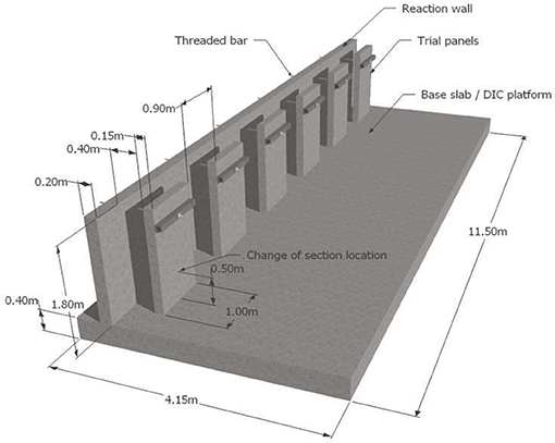
Figure 1. Concept model of trial structure.
A C40/50 structural concrete mix design was specified, referred to as the control mix, and is detailed in Table 1. This control mix was designed to have a consistency of class S3 and the measured slump when casting the trial panels was 100 mm.
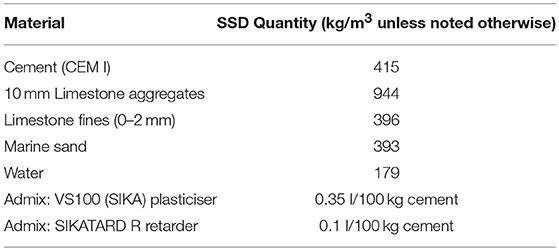
Table 1. Control mix design.
The trial structure was constructed over an 8-week period. The base slab was initially cast and allowed to cure for a minimum of 28 days before casting the reaction wall and finally the trial panels.
Trial Panel Contents and Construction Details
Each panel on the trial structure was used to test a particular self-healing technique or combination of techniques. These techniques are detailed in Table 2 and their setup is shown schematically in Figure 2.
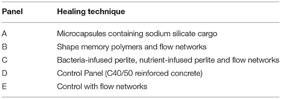
Table 2. Trial panel and embedded self-healing mechanisms.
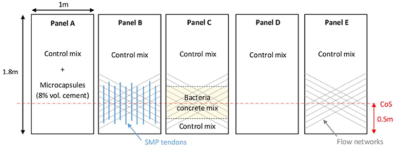
Figure 2. Self-healing panel arrangement.
Ready mix concrete was used and Panels B, D and E were cast using material supplied directly from the mixing truck. To ensure the quality and robustness of the control mix throughout the casting procedure a retarder was added to the mix. Casting, compaction and finishing were carried out in accordance with standard construction practice. For Panel A, prior to casting the concrete was transferred to a 120l Belle mixer, where the microcapsules were added. Panel C included a section that comprised concrete using CEM II cement and a lightweight aggregate of bacteria infused perlite particles. This was also mixed on-site using the 120l Belle mixer.
Panel A: Addition of Microcapsules Containing Sodium Silicate
Spherical, polymeric microcapsules, carrying a sodium silicate emulsion, were used in Panel A. Sodium silicate was selected as the healing compound, as it forms products of a similar nature to the host cementitious matrix. The potential of sodium silicate as a healing agent for cement-based composites was previously investigated, both in terms of crack closure and durability, by Kanellopoulos et al. (2015); Giannaros et al. (2016), who confirmed its compatibility in cementitious matrices. The microcapsules had a polymeric shell made of cross-linked gelatin and acacia gum giving a wall thickness ranging from 5 to 20 μm. Their cargo was an emulsion of sodium silicate in mineral oil (54% Mineral Oil, 42% Sodium Silicate, 4% Emulsifier by weight). The size of the microcapsules ranged from 300 to 700 μm and they had a density of ~1.0 gr/cm3. Figure 3 shows an optical microscope image of the microcapsules.
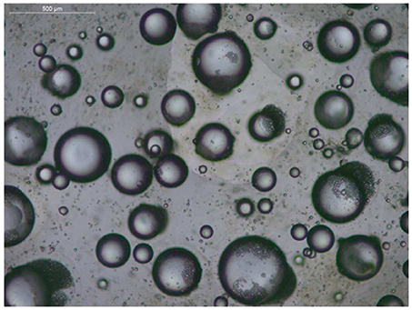
Figure 3. Microscope image of the microcapsules used in this study.
A total of 8% by volume of cement of microcapsules were mixed into the concrete using the onsite Belle mixer. As the microcapsules were provided by Lambson in a preserving aqueous solution, this added an additional small quantity of water to the concrete mix, increasing its water-cement ratio from 0.43 to 0.45. This had a minimal effect on the slump increasing it by < 20 mm. Figure 4 shows the microcapsules in solution prior to and during their addition to the mix.
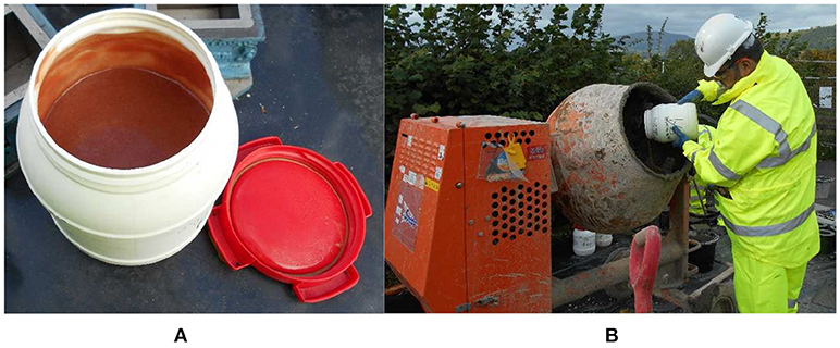
Figure 4. (A) Microcapsules in solution prior to mixing and (B) addition of microcapsules into the mix.
Panel B: Shape Memory Polymer Tendons and Flow Networks
Panel B contained a mat of SMP tendons and flow networks that were set up within the formwork prior to the control mix concrete being poured. These were tied onto the reinforcement in the concrete cover zone and were activated manually after casting.
Ten SMP tendon units were placed in the panel, which were designed, upon activation, to generate a stress of 0.5 MPa across the cracked external face. Each tendon contained 200 PET filaments, surrounded by a heating system and injection molded sleeves, as shown in Figure 5. The PET filaments were manufactured by Bradford University specifically for this project, and were found to be capable of generating a restrained shrinkage stress of 30 MPa in the laboratory. These tendons were 750 mm in length and placed at an eccentricity of 40 mm from the center of the panel's cross-section in a staggered layout, as shown in Figures 6, 7.
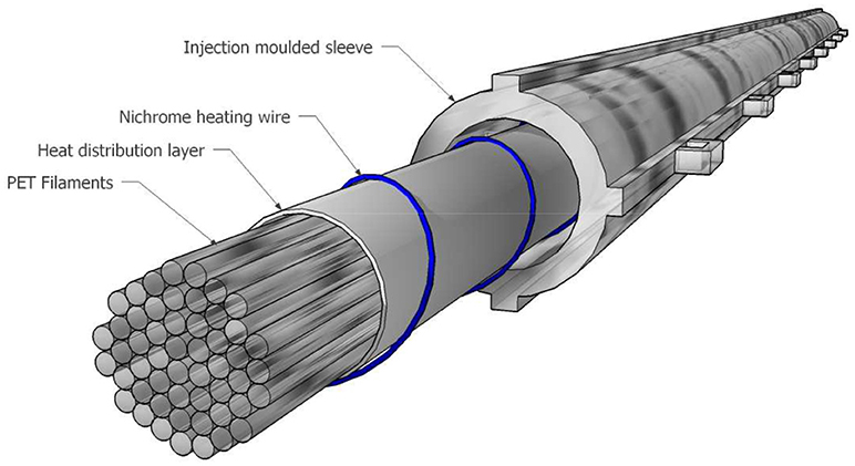
Figure 5. Shape memory PET tendon crack closure system (Teall et al., 2018).
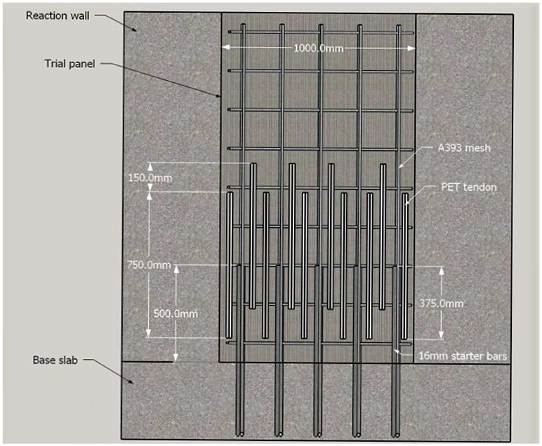
Figure 6. Position of SMP tendons within Panel B.
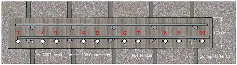
Figure 7. Cross-section of Panel B layout with PET tendons.
Flow networks were included in Panel B to allow the introduction of healing agents into the concrete. A 2D network of 4 mm diameter channels was created using polyurethane tubes, which were removed from the concrete after the formwork had been struck. The channels were connected using 3D printed joints made from polylactic acid (PLA), which were tied to the outermost reinforcement, allowing the networks to pass in front of the SMP tendons. At either side of the panel, the flow networks were terminated with lockable steel injection packers, which allowed each channel to be sealed individually to aid the loading and pressurizing of the network. The final layout of the tendons and flow networks within the panel prior to casting is shown in Figure 8.
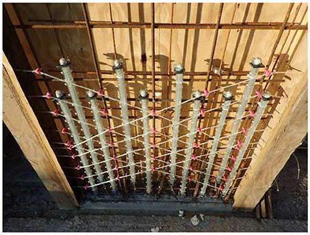
Figure 8. Layout of SMP tendons and flow networks in Panel B.
Panel C: Bacteria Concrete and Flow Networks
Following laboratory experiments in which different potential strains were investigated, the bacteria concrete mix developed by the University of Bath for use in the site trial contained spores of Bacillus pseudofirmus DSM 8715, infused into lightweight perlite aggregate particles. An organic mineral precursor, which included yeast extract and calcium acetate, was also included in separate aggregate particles as a food source for the bacteria.
Due to the challenge of producing a sufficient quantity of spores for an entire panel, it was decided that Panel C would contain three lifts. The first was a 250 mm layer of structural concrete using the control mix, the second a 500 mm layer of bacteria concrete in the zone in which the panels had been designed to crack, and the third a layer of the control mix to complete the panel. Panel C also contained flow networks as a potential feeding system for the bacteria in the later stages of testing. These networks were formed in the same way as in Panel B.
Panels D and E: Controls
Panels D and E were cast as controls. Panel D was cast using the control mix without any additions, while Panel E used the control mix together with flow networks as in Panels B and C. This was to investigate any impact on the structural properties because of the incorporation of these networks.
Loading Configuration, Monitoring, Measurement and Loading Procedure
Loading Configuration for the Panels
The cracks that were to be investigated for healing were created by damaging the panels using controlled loading. A threaded bar and a hollow ram hydraulic jack system was adopted to apply the load. This system had a bar running through the center each panel and reaction wall at 1.5 m above the base slab. The loading was distributed across the full width of the panel using a rectangular hollow steel waling beam, 100 × 100 mm in section and 10 mm in thickness. On the back face of the reaction wall, the threaded bar passed through a load cell and steel cradle to allow the load to be “locked off” once it had been applied. A hollow ram, hydraulic jack connected to a hand pump was then attached to the bar beyond the cradle to enable a load to be applied to the panels. The general arrangement of this loading system is shown in Figure 9. The reaction wall was designed to be of sufficient strength and stiffness to allow the loading to damage the panels whilst experiencing minimal damage and displacement itself. In this way, the panels were loaded as cantilever structures and the fractures appeared on their “front” faces to allow easy monitoring over time.
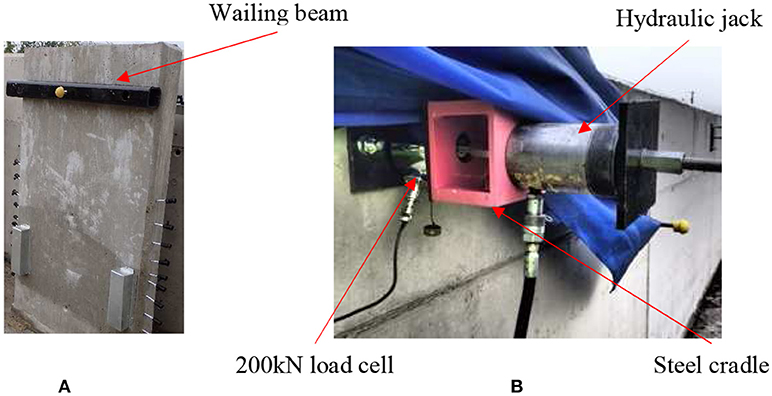
Figure 9. Loading arrangement (A) Front face of trial panel (B) Rear face of reaction wall.
Monitoring Equipment
Throughout the site trial, crack widths, deflections, strains, permeability, and applied loading were all monitored. These measurements were taken using a combination of DEMEC pips, optical microscope (Veho vms-004 20-400x), linear variable displacement transducers (unguided LVDT), load cells (200 kN annular compression), in-situ air permeability (Torrent Permeability Tester), an ultrasonic pulse velocity meter (Pundit PL-200) and a Digital Image Correlation (DIC) camera (LaVision Imager X-lite 8M CCD camera with DaVis software, 2015). National Instruments equipment and the LabVIEW (2014) software was used to collect all the data. Panel B also contained temperature monitoring equipment and an electrical activation system for the SMP tendons.
The surface of each panel was painted with white then black emulsion paint to create a speckled pattern that could be picked up by the dual-camera DIC system. For Panels A, C and D the pattern was only applied to half of the panel width to allow a comparison to be made between the permeability measurements obtained on the painted and unpainted surfaces. The surfaces of Panels B and E were completely covered in the speckled pattern to allow monitoring of the strain development over the whole of the panel to determine the performance of the SMP tendons.
Crack Width and Displacement Measurements
Six LVDTs were used to monitor each panel and the locations of these are shown in Figure 10. The two LVDTs were placed on the front face to monitor cracks opening and four LVDTs were located between each panel and the reaction wall to monitor the displacement of the panel and reaction wall during loading. The LVDTs were attached to a RHS steel column, which was in turn bolted to the base slab using chemical anchor bolts, to provide displacement readings of the panel independent of the reaction wall. All LVDTs were covered with aluminum sheet boxes to protect them from the weather.
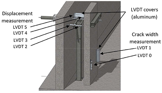
Figure 10. Locations of LVDTs on trial panels.
In addition to the LVDTs 3 sets of DEMEC pips, with a gauge length of 100 mm, were placed on the front left and right face of each panel, as shown in Figure 11. Five crack width measurements were taken at the change of section (CoS) location across the width of each panel using a hand held microscope. A notched gauge was used as a scale for each image and the crack width was measured perpendicular to the crack direction using ImageJ software (Schneider et al., 2012). Three measurements were made from each image, at approximately equal spacing across the field of view and then averaged to give a single crack width value for that location.
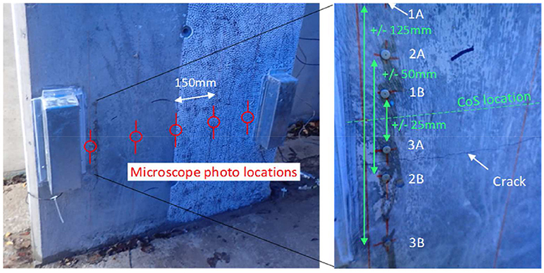
Figure 11. Location of DEMEC pips and microscope images for crack width measurements.
Air-Permeability Measurements
A non-destructive air permeability measurement device (Torrent device) was used to measure the permeability of Panels A, B, C, and D prior to cracking and just after unloading. These values provided a base line for comparison with permeability measurements taken over the entire monitoring period. For all panels three permeability measurements were taken in the expected cracking location prior to loading. For Panels A and C, a further 3 measurements were taken over the height of the panel to monitor any permeability variations due to the addition of the self-healing techniques. After unloading, permeability measurements were taken only in the cracked region.
Loading Procedure
The testing and monitoring schedule adopted is shown in Table 3. Each panel was loaded at a rate of ~200 N/s until a visible crack appeared at the CoS location ~500 mm above the base slab. The panels were then further loaded until a 0.5 mm crack was recorded by the front of panel LVDT measurements, and this resulted in a significant residual crack when the load was removed. Panels B and E were loaded to 20 kN post-cracking to ensure repeatability following activation of the polymer tendons. The load in Panel E was then “locked off” by tightening the locking nut to ensure that any losses in load could be attributed to creep of the panel. Prior to activating the SMPs tendon, Panel E was unloaded from the locked off state and together with Panel B was again loaded and unloaded to 20 kN, to remove the contribution of short term autogenous healing.
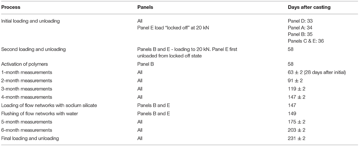
Table 3. Site trial testing and monitoring schedule.
The crack width was then measured by taking photos of the crack at the five locations across the width of each panel, and measuring the distance between the DEMEC pips as described in section Results and Discussion. Once the crack width had been measured, the load was reduced back to zero in a controlled manner over a period of a few minutes. At zero load, the crack widths were measured again. Throughout the loading, sustained loading and the unloading cycle the DIC camera system was used to take sequential images for post-processing.
Measurements from all of the LVDTs were taken continuously at a sample rate of 4 Hz during the loading and unloading stages. Single displacement measurements for each LVDT were also taken at 28-day intervals following the initial loading/unloading stage, together with optical microscope crack width and DEMEC gauge measurements.
Results and Discussion
One of the aims of the M4L project was to demonstrate that the self-healing techniques that were being investigated could be employed in large-scale applications and this was successfully achieved as evidenced in Figure 12. Although it was originally intended to cast six panels, the central panel wasn't used, being kept as a reserve in case of unforeseen problems during construction. The following sections describe some of the many valuable lessons learnt from the construction of these panels.
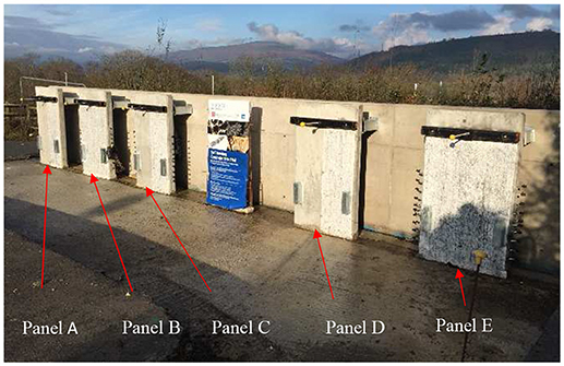
Figure 12. Site trial panels after initial loading.
Scaling-Up of Self-Healing Techniques
The site trials were an opportunity to take the healing techniques out of the laboratory and to apply them at a larger scale in a construction environment. The M4L self-healing concrete trials achieved this primary aim as all four individual healing technologies were successfully deployed. The physical implementation was shown to be a relatively straightforward process with many positive indicators. The microcapsules were manufactured in bulk, by Lambson, and were readily mixed into the concrete on site. The bacteria infused concrete preparation took significantly longer than expected, however the development of an automated manufacturing capacity, capable of producing a sufficient volume for commercial use should be relatively straightforward. The crack closure forces generated by the SMP polymers are very much dependent on the shrinkage stress generated in the individual tendons. The compromise between the shrinkage stress generated and hence the number of tendons embedded into the concrete showed that this technique is feasible at this larger scale. The installation of the flow networks in these full scale panels was straightforward and demonstrated that it was feasible to repeatedly flush healing agent through the cracks in the panels.
Concrete Strength
The target characteristic cube strength of the concrete for the panels was 40 MPa and when measured at 28 days in accordance with BS EN 12390-2 was found to be 59.3 MPa. The bacteria infused concrete was measured at 35.1 MPa, which is below the control concrete, but very close to the target strength. This was the first time the bacteria mix had been tried in this quantity and outside the lab environment. The retention of workability of this mix was significantly less than expected, which made it extremely difficult to manufacture a reliable cube specimen after the wall had been cast. Likewise, although previous work (Giannaros et al., 2016; Kanellopoulos et al., 2016) had indicated that the addition of microcapsules would not significantly affect the strength of the concrete, the 28-day results obtained from the site trials were very inconsistent, with a mean strength of 42.2 MPa. The reason for this was that difficulties were experienced in hand compacting the cube specimen as a consequence of casting them at the very end of the casting sequence having double handled the concrete to enable the microcapsules to be added to the mix. This meant that the workability of the concrete used for the cubes had deteriorated significantly by the time they were being cast, which resulted in some honeycombing and the lower than anticipated strength. Similar workability issues were not experienced while placing the concrete in the panel itself and therefore it is reasonable to conclude that the strength of the panel was not compromised by the inclusion of the microcapsules.
Structural Behavior
The load/displacement curves for all panels during the initial loading stage are presented in Figure 13. This comparison explores the differences in the stiffness and flexural strength of the panels. The displacement values were obtained from LVDTs 2 and 4 positioned at the level of the loading bar (Figure 10) and measured the displacement of the panel relative to the mounting column. For the purposes of comparing overall displacement, the average value of the two transducers was used, taking account of any twisting in the panels.
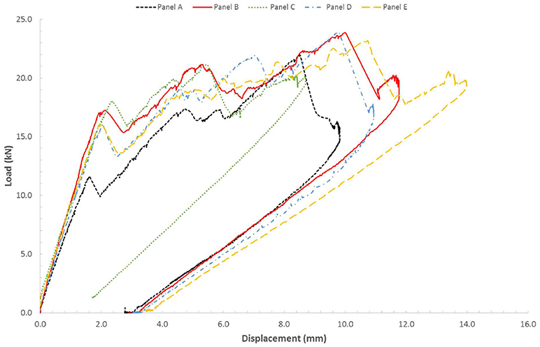
Figure 13. Load-displacement curves for all panels during the initial loading stage.
The load-displacement profiles are similar for all panels, but with some key discrepancies. For Panels B, C, D, and E, initial small reductions in load can be observed between 16 and 18 kN and this corresponds to the first cracks at the base of the wall. Fluctuations in load are observed beyond 18 kN with a second significant reduction in load at around 21–22 kN corresponding to a second crack about 200–300 mm above the base. Panel A, containing microcapsules, experienced initial cracking at about 250 ± 20 mm above the base at the much lower load of 11.6 kN, however, this panel did crack at the base of the panel at around 17 kN which is consistent with the other panels. Further load was then applied until a crack formed at the CoS location. Panel C, containing the bacterial concrete layer, experienced cracking at the CoS location with the least amount of deflection and Panel E had the largest deflection at 14.35 mm.
It can also be seen that the gradient of the initial loading curve for Panel B is slightly greater than that of all of the other panels. This indicates that this panel has a greater stiffness, probably due to the contribution of the PET tendons. The loading curve of Panel A has the smallest gradient, indicating that this panel has the lowest stiffness. This could be a result of the inclusion of the polymeric capsules into the mix or the slightly higher water-cement ratio of this concrete compared to the control, and it is consistent with the cube strength results presented in section Concrete Strength.
Figure 14 shows DIC images of all five panels immediately following cracking at the CoS. The loads displayed are indicative of the peak load immediately before the formation of these cracks. As indicated when discussing the experimental set-up, Panels A, C and D are shown as half-panels, to enable permeability measurements to be taken across the non-painted side of the panels.
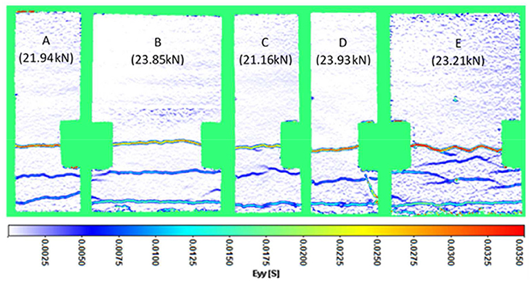
Figure 14. DIC images of all panels at peak load during initial loading.
The DIC images show some branching of the cracks. This is particularly evident on Panel E, which has flow networks in addition to the control concrete. The presence of these multiple cracks and a larger displacement of the panel at higher loads suggests that there is a loss of strength but an increase in ductility due to the inclusion of the flow networks.
Table 4 compares the load and displacement of each panel at various points in the trial. The values of the load to cause cracking 500 mm above the base are consistent with what might be anticipated to be the tensile strength of the concrete based on the cube strengths, with the cracking loads of the microcapsule and bacteria panels being ~8% and 11% lower than those of the panels with the control mix in them. Comparison of the loads and displacements immediately prior to unloading with those achieved after 6 months does not provide any evidence of any regain in strength as a result of self-healing. However, given the relatively short period between these loading events and the wintry weather conditions experienced during this time, it is unlikely that the levels of autogenic and mineral healing that could be achieved would be sufficient to have any real impact on the strength and stiffness of the panels.
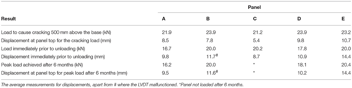
Table 4. Loading-displacement comparison at various points in initial and final loading.
Visual Assessment of Healing
The tests were designed to minimize any autogenous healing due to early hydration and to focus attention on the functionality of the healing techniques 28 days after casting. Figure 15 shows microscope images of typical cracks at the locations shown in Figure 11 after (a) initial loading, (b) 6 months, and (c) final loading. However, visual quantification of healing proved challenging at this larger scale because the images were only a snapshot of the whole crack length. Furthermore, visual assessment only provides an indication of surface cracking, although as can be seen in Figure 15b), there is some evidence of healing as indicated by material precipitation in the cracks of all the panels.
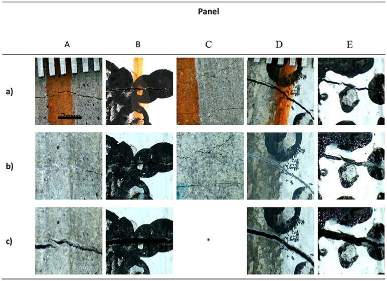
Figure 15. Selected microscope images of cracks after (a) initial loading, (b) 6 months, and (c) final loading. (* Panel not loaded after 6 months).
The Effect of Healing Techniques on the Crack Width
A summary of the peak and residual crack width values as measured using the optical microscope are shown in Table 5. The optical microscope measurements were thought to be the most applicable since they were a direct measurement of the crack. The LVDT measurements imply larger crack width values as they have a longer gauge length and therefore measure multiple micro-cracks within this length. The measurements taken from the microscope photos and from the DEMEC pips spanning the crack at the CoS location are very similar, giving confidence in the reliability of the measurements of crack width that were obtained. The residual crack measurements show that, following unloading of the panels, a significant residual crack remained in each panel (between 0.06 and 0.16 mm).
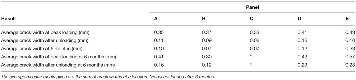
Table 5. Crack widths during and after loading.
Although the intention was to produce very similar crack widths in all panels, the nature of the cracking process resulted in some variability between the panels. It is unlikely that this was due to the presence of the self-healing techniques but was more probably a result of the inherent variability that there is in site based testing. The changes in the average crack width after 6 months were relatively small, both before loading, at the peak load and after unloading, but generally they had reduced over time. The one exception was Panel E, which exhibited an unexplained increase before loading at 6 months. During loading at 6 months, Panel B exhibited a reduction in crack width at the peak load, which may have been a consequence of the presence of the activated SMP.
Conclusions
This paper has described the use of four techniques, developed as part of the Materials for Life research project, to facilitate the self-healing of concrete. Details of the design, construction, and subsequent testing and monitoring of five full-scale reinforced concrete trial panels have been given. These self-healing concrete trials have been successful in achieving their primary aim, which was to scale-up the four individual healing technologies and implement them in a full-scale structure on a live construction site. The physical implementation was shown to be a relatively straightforward process, but a number of lessons have been learnt from these trials, which will enable the techniques to be enhanced and their application to become more commonplace.
What was very evident from these trials is that the different self-healing techniques will be best suited to different applications and that it will therefore be necessary to clearly identify the damage mechanism that is being targeted to tailor the technique that is adopted. Further research is now being undertaken under the auspices of the RM4L programme grant (EP/P02081X/1), which seeks to extend significantly the range of damage that can be addressed and to enhance the reliability, autonomy and applicability of the techniques that are available. These initial results are sufficiently positive to give confidence that these techniques warrant further investigation, working toward reducing and removing the requirement for inspection, maintenance and repair of concrete structures.
Data Availability Statement
The datasets generated for this study can be found in the Cardiff University data archive at http://doi.org/10.17035/d.2018.0055749445.
Author Contributions
RL was the PI of the project. AJ, AA-T, DG, and KP were the Co-Is. RD, MP, TS, and AK were the four RAs responsible for the site trials and OT was the Costain sponsored PhD student responsible for liaising with the contractors on site and for undertaking the majority of the testing.
Funding
The work reported in this paper was carried out as part of the EPSRC funded project Materials for Life (M4L), reference EP/K026631/1 and supported with PhD studentship funding from Costain Group PLC.
Conflict of Interest Statement
The authors declare that the research was conducted in the absence of any commercial or financial relationships that could be construed as a potential conflict of interest.
Acknowledgments
Thanks must go to the EPSRC for their funding of the Materials for Life (M4L) project (EP/K026631/1) and to the Costain Group PLC. for their industrial sponsorship of the project, PhD and lead author. This site trial was a major component of OT PhD thesis and the team are very appreciative of his hard work and dedication. The authors are also particularly grateful to Aled Philips of Arup, Cardiff for the suggestion of what form the site trial might take and Toby Bedford of Costain for coordinating the activities on site.
References
Alazhari, M., Sharma, T., Heath, A., Cooper, R., and Paine, K. (2018). Application of expanded perlite encapsulated bacteria and growth media for self-healing concrete. Constr. Build. Mater. 160, 610–619. doi: 10.1016/j.conbuildmat.2017.11.086
Davies, R., Jefferson, A. D., Lark, R. J., and Gardner, D. R. (2015). “A novel 2D vascular network in cementitious materials,” in fib Symposium 2015. (Copenhagen).
de Rooij, M., Tittelboom, K.V., Belie, N.D., Schlangen, E. (2013). Self-Healing Phenomena in Cement-Based Materials: State-of-the-Art Report of RILEM Technical Committee 221-SHC: Self-Healing Phenomena in Cement-Based Materials. Springer Science & Business Media.
Dunn, S. C., Jefferson, A. D., Lark, R. J., and Isaacs, B. (2011). Shrinkage behavior of poly(ethylene terephthalate) for a new cementitious-shrinkable polymer material system. J. Appl. Polym. Sci. 120, 2516–2526. doi: 10.1002/app.33109
Gardner, D., Jefferson, A., Hoffman, A., and Lark, R. (2014). Simulation of the capillary flow of an autonomic healing agent in discrete cracks in cementitious materials. Cement Concrete Res. 58, 35–44. doi: 10.1016/j.cemconres.2014.01.005
Giannaros, P., Kanellopoulos, A., and Al-Tabbaa, A. (2016). Sealing of cracks in cement using microencapsulated sodium silicate. Smart Mater. Struct. 25:084005. doi: 10.1088/0964-1726/25/8/084005
Hazelwood, T., Jefferson, A. D., Lark, R. J., and Gardner, D. R. (2015). Numerical simulation of the long-term behaviour of a self-healing concrete beam vs standard reinforced concrete. Eng. Struct. 102, 176–188. doi: 10.1016/j.engstruct.2015.07.056
Isaacs, B., Larks, R., Jefferson, T., Davies, R., and Dunn, S. (2013). Crack healing of cementitious materials using shrinkable polymer tendons. Struct. Concrete 14, 138–147. doi: 10.1002/suco.201200013
Jefferson, A., Joseph, C., Lark, R., Isaacs, B., Dunn, S., and Weager, B. (2010). A new system for crack closure of cementitious materials using shrinkable polymers. Cement Concrete Res. 40, 795–801. doi: 10.1016/j.cemconres.2010.01.004
Kanellopoulos, A., Giannaros, P., and Al-Tabbaa, A. (2016). The effect of varying volume fraction of microcapsules on fresh, mechanical and self-healing properties of mortars. Constr. Build. Mater. 122, 577–593. doi: 10.1016/j.conbuildmat.2016.06.119
Kanellopoulos, A., Qureshi, T. S., and Al-Tabbaa, A. (2015). Glass encapsulated minerals for self-healing in cement based composites. Construc. Build. Mater. 98, 780–791. doi: 10.1016/j.conbuildmat.2015.08.127
Schneider, C. A., Rasband, W. S., and Eliceiri, K. W. (2012). NIH image to imagej: 25 years of image analysis. Nat. Methods 9, 671–675. doi: 10.1038/nmeth.2089
Teall, O. (2016). Crack Closure and Enhanced Autogenous Healing of Structural Concrete using Shape Memory Polymers. PhD. Cardiff University. Available online at: http://orca.cf.ac.uk/id/eprint/100250
Keywords: self-healing, concrete, site-trials, materials for life, design, construction, testing
Citation: Davies R, Teall O, Pilegis M, Kanellopoulos A, Sharma T, Jefferson A, Gardner D, Al-Tabbaa A, Paine K and Lark R (2018) Large Scale Application of Self-Healing Concrete: Design, Construction, and Testing. Front. Mater. 5:51. doi: 10.3389/fmats.2018.00051
Received: 01 June 2018; Accepted: 02 August 2018;
Published: 04 September 2018.
Edited by:
Xiangming Zhou, Brunel University London, United KingdomCopyright © 2018 Davies, Teall, Pilegis, Kanellopoulos, Sharma, Jefferson, Gardner, Al-Tabbaa, Paine and Lark. This is an open-access article distributed under the terms of the Creative Commons Attribution License (CC BY). The use, distribution or reproduction in other forums is permitted, provided the original author(s) and the copyright owner(s) are credited and that the original publication in this journal is cited, in accordance with accepted academic practice. No use, distribution or reproduction is permitted which does not comply with these terms.
*Correspondence: Robert Davies, daviesre11@cardiff.ac.uk