Rotating structures in low temperature magnetized plasmas—insight from particle simulations
 Jean-Pierre Boeuf
- 1Université de Toulouse; UPS, Institut National Polytechnique de Toulouse; LAPLACE (Laboratoire Plasma et Conversion d'Energie), Toulouse, France
- 2Centre National de la Recherche Scientifique, LAPLACE, Toulouse, France
The E × B configuration of various low temperature plasma devices is often responsible for the formation of rotating structures and instabilities leading to anomalous electron transport across the magnetic field. In these devices, electrons are strongly magnetized while ions are weakly or not magnetized and this leads to specific physical phenomena that are not present in fusion plasmas where both electrons and ions are strongly magnetized. In this paper we describe basic phenomena involving rotating plasma structures in simple configurations of low temperature E × B plasma devices on the basis of PIC-MCC (Particle-In-Cell Monte Carlo Collisions) simulations. We focus on three examples: rotating electron vortices and rotating spokes in cylindrical magnetrons, and azimuthal electron-cyclotron drift instability in Hall thrusters. The simulations are not intended to give definite answers to the many physics issues related to low temperature E × B plasma devices but are used to illustrate and discuss some of the basic questions that need further studies.
Introduction
In discharges devices operating at low pressure, the electron mean free path is longer than the discharge dimensions and plasma sustainment by electron impact ionization is possible only if the electrons are confined. This can be achieved by using an external magnetic field with a proper space distribution. In a dc discharge, the presence of an external magnetic field B perpendicular to the electron path from cathode to anode (i.e., perpendicular to the applied electric field E) can significantly increase the residence time of electrons in the discharge because electron trajectories tend to be trapped along the magnetic field lines. The magnetic field acts as a barrier to electron transport from cathode to anode. Such E × B configuration is common to a large variety of low pressure discharge devices, from Penning discharges (Penning ionization gage) to cylindrical and planar magnetrons, and to End-Hall ion sources, anode layer thrusters, and Hall thrusters. In the presence of crossed electric and magnetic fields electrons are also subject to a drift in the E × B direction and an essential feature of all E × B devices is that efficient electron confinement is achieved only if the E × B direction does not intercept a wall, i.e., the E × B direction must close on itself (“closed drift” devices). Typical E × B devices are therefore based on a cylindrical geometry with the E × B drift in the azimuthal direction.
The E × B configuration is in principle efficient for electron confinement but the large E × B electron current (Hall current) can also be very favorable to the development of instabilities leading to “anomalous transport” across the magnetic field. These instabilities can generate azimuthal plasma non-uniformities and polarization, leading to the formation of an azimuthal electric field which may break the electron confinement by inducing electron drift across the magnetic field. Although the possible existence of such instabilities is well known, a qualitative and quantitative description of them is missing in most practical situations and design is still largely empirical.
In this paper we discuss, on the basis of results from Particle-In-Cell Monte Carlo Collisions (PIC-MCC) simulations, the formation of plasma non-uniformities perpendicular to the magnetic field in cylindrical magnetrons and Hall thrusters that can be responsible for anomalous transport across the magnetic field. The goal of the paper is not to provide a complete review of instabilities and anomalous transport in low temperature E × B devices (this would be a formidable task), but to address these questions on a few specific examples that are of interest because they correspond to very basic situations or to important applications. The references to works by other groups on this topic are therefore far from being exhaustive. We also restrict ourselves to relatively low current conditions where the magnetic field induced by the plasma current is negligible with respect to the external magnetic field.
Crossed-Field Discharge Devices and Instabilities
Classical Electron Transport in E × B Configurations
Before describing the principles of typical low temperature E × B plasma devices, we briefly recall here the elementary and classical transport properties of charged particles in perpendicular electric and magnetic fields in the presence of collisions. In the presence of a magnetic field perpendicular to the electric field the electron drift velocity parallel to E, v⊥, is reduced by a factor (1 + Ω2e⧸v2) with respect to the unmagnetized case, where Ωe = eB⧸m is the electron cyclotron angular frequency and ν the electron collision frequency. Introducing the Hall parameter h = Ωe⧸v the mean velocity parallel to the electric field E and to the E × B direction, can be written respectively as:
In the absence of collisions the h parameter becomes infinite, and the drift parallel to the electric field tends to zero (electrons are trapped around the magnetic field) and the amplitude of the E × B drift velocity tends to the collisionless limit E⧸B. When the Hall parameter h is small but not zero one can write, to the first order in h : v⊥ ≈ −E⧸Bh and vE×B ≈ E⧸B. The electron mobility in the direction of the electric field is therefore μe⊥ = μ*e1⧸(1 + h2) where μ*e = e⧸mν is the mobility without magnetic field, and tends to μe⊥ ≈ μ*e⧸h2 = 1⧸Bh for h ≫ 1.
The equations above are in principle also valid for ions. However, in a number of practical low temperature E × B plasma devices, the Larmor radius of ions is not small with respect to the dimensions of the system and the ions can be considered as unmagnetized.
In this classical theory, the Hall parameter h controls electron confinement. In typical applications (magnetron sputtering, ion sources) the pressure is in the 1–10 mtorr range and the magnetic field in in the 10–100 mT range. Therefore, the Hall parameter is between 10 and 104 (h can be much larger in Penning discharges or magnetrons used as pressure gages, see below).
E × B Plasma Devices
As said in the introduction, efficient electron confinement is obtained only if the Hall current is closed. This can be achieved if E × B is in the azimuthal direction of a cylindrically symmetric geometry. B can be axial and E radial as in the Penning cell and cylindrical magnetron geometry of Figures 1A–C, or, inversely, E can be axial and B radial as in the planar magnetron and Hall ion sources of Figures 1D,E. We briefly summarize here the principles and properties of these crossed-field discharges. More details and references can be found in the early review of low pressure magnetically confined discharges by Hooper [1], in the paper on instabilities in low pressure crossed-field devices by Redhead [2] and in the more recent reviews on E × B devices by Keidar and Billis [3], and Abolmasov [4]. Depending on pressure, magnetic field, and applied voltage, different regimes of the discharges in the E × B configurations of Figure 1 can be observed and Abolmassov [4] proposed a classification of these regimes based on the categories defined by Schuurman [5] for Penning discharges. We will not go in the details of this classification here, but we will distinguish two important regimes where the physics and applications are quite different:
(1) The low pressure regime (typically below 10−4 torr) where the electron confinement time is much longer than the ion transit time in the device and the “plasma” is non-neutral. The main applications of this regime correspond to pressure gages and sputter-ion pumps [2].
(2) The “high-pressure” regime (above 10−4 torr, typically 1–10 mtorr in the applications) where the plasma is quasi-neutral and the main applications are in surface processing and ion sources.
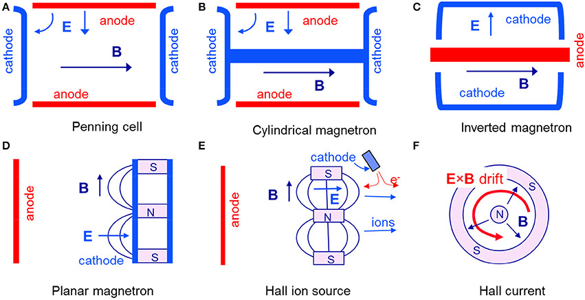
Figure 1. Schematic representation of the geometry of different E × B devices. The devices are cylindrically symmetric (horizontal axis). (A–C): axial B, radial E; (D–F): axial E, radial B. (E) does not represent a real device but shows the principle of Hall ion sources which are similar to planar magnetrons (D) but with an electron emitting cathode instead of a planar cathode; in this configuration the potential drop due to the applied voltage takes place in the plasma volume and not in a cathode sheath, leading to extraction and acceleration of the ions out of the device; many variations are possible depending on the position of the magnetic barrier and on the anode geometry.
The operation of a low pressure (below 10−4 torr) magnetically confined cold-cathode discharge was demonstrated by Phillips [6] in 1898, and Penning [7], Penning [8] showed in the 1930s that such sources could be used as pressure gages. The Penning gage also called Phillips Ionization Gauge (PIG) has been improved over the years and can now operate at pressure as low as 10−10 torr. Penning also observed that the gage was exhibiting a pumping effect and the sputter-ion pump was invented in the 1950s (Redhead [2] and references therein). A sputter-ion pump uses a Penning cell discharge to sputter titanium atoms from a target; the gas is pumped by chemisorption on the titanium film deposited on the anode.
In the 1–10 mtorr pressure range E × B discharges are used in important and different applications such as surface treatment (magnetron sputtering and deposition of thin films) and satellite propulsion (gridless ion sources, lower end of this pressure range). Magnetron discharges can efficiently combine sputtering and deposition. Ions are accelerated to high energy in the cathode sheath and sputter the cathode target, and because of the low pressure, sputtered atoms can be easily and efficiently deposited on a remote substrate. In reactive magnetron sputtering compound films, such as nitrides, oxides, carbides or their combinations can be obtained by the sputtering of metallic targets in the presence of reactive gasses [9]. There has been a considerable literature [9–13] on magnetron sputtering in the last 30 years, with an increasing number of publications on high power impulse magnetron sputtering (HiPIMS). In HiPIMS, the peak power can be very high, leading to a high plasma density and a high ionization fraction of the sputtered vapor and thus to a better control of the energy and direction of the deposition species [12, 13]. In some applications, high-current low-energy ion beams are used in conjunction with thin-film deposition to increase adhesion, modify stress, increase density or hardness of the film. Specific ion sources such as the End-Hall ion source have been designed for these applications [14] (see also the modeling of End-Hall ion sources in Oudini et al. [15], Oudini et al. [16]). The End-Hall ion sources are part of a larger class of Hall ion sources whose principle is shown on Figure 1D. A magnetic barrier is placed between the anode and an emitting cathode. In the example of Figure 1D, the applied electric field is axial and the magnetic field, perpendicular to the electric field, must be radial to allow closed drift electron current. Because the cathode is emitting electrons the ion sheath around the cathode is neutralized and the electric field associated with the applied voltage distributes in the plasma volume, in the region where the electron conductivity is lowered by the magnetic field, i.e., in the magnetic barrier. Ions are practically insensitive to the magnetic field and are collisionless; they are accelerated by this electric field out of the device. This gridless extraction and acceleration of ions is the basis of Hall thrusters [17].
Instabilities, Rotation of Spatial Structures and Anomalous Transport in E × B Devices
Instabilities are often present in low temperature magnetized plasmas as well as in fusion or space plasmas. They can lead to waves and field fluctuations that can play a role similar to the role of collisions and enhance electron transport across the magnetic field (“anomalous transport”). Another feature which is specific to E × B configurations such as those described above is the fact that the large electron drift in the E × B direction (Hall current) can also lead to instabilities and to charge separation and the formation of plasma non-uniformities and a non-zero component, EH, of the space charge field along this direction. Such an azimuthal component of the electric field can in turn generate an axial EH × B current, i.e., an electron current across the magnetic barrier. Because of the E × B configuration the plasma non-uniformities or plasma structures formed in the azimuthal direction are rotating around the symmetry axis.
For pressure below 10−4 torr and typical device dimensions (few centimeters) and magnetic field intensity (in the 0.01–0.1 T range), the electron confinement time in Penning or magnetron discharges is much larger than the ion transit time. Therefore, the electron density is larger than the ion density and the plasma is not quasineutral or a large region of the electrode gap is not quasi-neutral (such region is sometimes termed as “electron sheath” [18] but we see below that this “electron sheath” often evolves into electron vortices). In this regime it is suspected that diocotron type instabilities play an important role (there is no consensus on this [18]). The diocotron instability [19] is known to occur in low density (ω2pe << Ω2e, where ωpe is the electron plasma frequency and Ωe the electron cyclotron frequency) non-neutral electron plasma columns radially confined by a uniform axial magnetic field and is driven by a strong shear in the azimuthal rotation velocity E × B (analog to a Kelvin-Helmhotlz instability in fluid mechanics). The diocotron instability was first investigated theoretically by McFarlane and Hay [20], Levy [21], Levy [22], and observed in experiments by Webster [23]. An interesting feature of the diocotron instability is that it leads to the formation of two-dimensional (2D) electron vortices parallel to the magnetic field and that interact through the space charge potential. The diocotron instability in non-neutral plasmas has been thoroughly studied in dedicated experiments where pure electron columns are confined in a Penning-Malmberg trap by an axial magnetic field and electrostatically trapped in the axial direction [24]. Such systems are excellent for the study of 2D fluid vortices, turbulence, and self-organization since the 2D drift-Poisson equations governing a magnetized electron column are isomorphic to the Euler equation governing a constant density inviscid fluid [25, 26]. We will see below [Section Electron Vortices at Low Pressure (<10−4 torr)] that PICC MCC simulations predict that electron vortices also form in self-sustained low pressure magnetized discharges under conditions where these discharges are used in applications as pressure gages.
For applications of low temperature magnetized plasmas to surface processing or ion sources, the operating pressure is above 10−4 torr, typically in the 1–10 mtorr range, and most of the discharge volume is filled with a quasi-neutral plasma. Fluctuations of the discharge current and of the plasma density in a large frequency range have been measured in a number of studies in simple cylindrical or planar magnetron configurations [27–29]. In the more complex configuration of planar magnetrons it is generally admitted that instabilities and anomalous transport across the magnetic field are present but there is no real quantification of these effects. In high power magnetrons (HiPIMS), researchers have recently reported the presence of rotating structures, termed as “rotating spokes” [30–32]. These rotating spokes are described as rotating regions of enhanced ionization associated with an electric potential structure with an azimuthally directed electric field. The role of plasma-electrode interactions (secondary electron emission, sputtering) or of phenomena induced by particle and energy balance in the volume of the magnetized plasma in the formation of these rotating spokes is still to be clarified. Some authors of the studies of rotating spokes in HiPIMS mention a possible analogy with the rotating spokes reported in pulsed high-power homopolar E × B discharges studied in the 1970s–1980s in the context of fusion and of the Critical Ionization Velocity (CIV) concept introduced by Alfven [33], Piel [34]. We show in Section Rotating Spokes at Higher Pressure (>10−3 torr) recent PIC MCC simulation results in a cylindrical magnetron geometry, that appear to be very consistent with some theoretical interpretation of rotating spokes in homopolar discharges.
Azimuthally rotating spokes have also been observed in Hall thrusters and were described in the 1960s by Janes and Lowder [35] who suggested that the rotation of the spoke could be due to a coupling between the density non-uniformities and the ionization process. More recent papers also describe the observation of rotating spokes in Hall thrusters [36–38]. The group at PPPL [37] showed evidence, in a cylindrical Hall thruster, of the presence of spokes rotating at about 10% of the local E × B speed, and deduced from measurements on a segmented anode that on the average 50% of the total current was conducted by the spoke. The physical mechanism responsible for the spoke was not clearly identified although the authors mention that the mechanism could be ionization related. Many other types of oscillations and azimuthal instabilities are present in Hall thrusters [39] and some of them certainly play a role in cross-field electron transport. Among those, the azimuthal electron-cyclotron drift instabilities evidenced in the work of Adam et al. [40], Ducrocq et al. [41], Adam et al. [42] is discussed in Section Electron Cyclotron Drift Instability in a Hall Thruster Type Magnetic Barrier.
Particle-In-Cell Simulation
The principles of Particle-In-Cell Monte Carlo simulations applied to low temperature plasmas have been described in a number of papers and the model we use [43, 44] is standard. We only mention here the features that are specific to our problem. Although three-dimensional PIC MCC simulations are possible they are still quite cumbersome even for low temperature plasmas and need massively parallel computing. We restrict ourselves here to 2D simulations. The difficulty of using PIC MCC simulations to model self-consistent discharges is that the time to reach steady state can be very long with respect to the inverse of the plasma frequency and to the collision time. The discharge must be simulated on time scales much longer than the charged particle transit time between the electrodes, which can be quite large in magnetized plasmas. So even 2D simulations are time consuming and it is difficult to simulate large devices or large plasma densities. In order to grasp the possible formation of instabilities related to the E × B drift it is essential that the 2D simulation domain be perpendicular to the external magnetic field. Using 2D models obviously limits the parameter domain where the simulations represent a reality but 2D simulations may be appropriate in a number of practical situations where the 3rd dimension does not play an essential role in the physics or can be taken into account in a simplified way. This is the case in magnetized plasma columns operating in a flute mode where the plasma can be considered homogenous along the magnetic field and if plasma waves in the axial direction are negligible. The plasma is however generally bounded at the end of the column and it may be important to take into account possible charged particle losses at these boundaries. In pure electron plasmas electrons are electrostatically trapped along the column axis and the 2D approximation is very good provided that the length of the column is much larger than its radius. In cylindrical magnetrons, the ends of the column (see Figures 1B,C) are metallic plates that are generally at the cathode potential and can collect positive ions and (possibly) electrons.
To account for the charged particle losses at the end walls, we proceed as follows. We assume that the electric potential along the magnetic field (in the direction parallel to the magnetic field) is constant (zero axial electric field). The electron trajectories are followed in the three directions (the electric field is calculated only in 2D, i.e., in the plane perpendicular to the magnetic field). When an electron reaches one of the end plate the electron is lost if its energy in the direction parallel to the magnetic field is larger than the potential drop between the plasma and the end plate (sheath voltage), otherwise it is reflected back in the plasma. The ion losses are estimated by defining a loss frequency equal to 2uB⧸L where uB = (kTe⧸m)1/2 is the Bohm velocity deduced from the local electron temperature Te. At each time step, a Monte Carlo technique is used to choose, according to this frequency, the ions that will be lost to the end walls assuming that the ions are distributed uniformly along the plasma column. The approximation of a uniform density along the plasma column could certainly be improved and this would lead to a correcting factor in the ion loss frequency 2uB⧸L. We consider that this approximation is sufficient for the purpose of this paper.
Most of the results presented below have been obtained in argon using the electron-neutral cross-section of Phelps database [45] and a constant ion-neutral charge-exchange collision cross-section of 8 × 10⁻¹⁹ m2, as in Boeuf and Chaudhury [46]. The simulation of electron-cyclotron drift instabilities of section Electron Cyclotron Drift Instability in a Hall Thruster Type Magnetic Barrier have been performed in xenon using the electron-neutral cross-sections of Siglo database [47]. Finally we note that the 2D simulations presented in this paper have be performed in Cartesian (rectangular) coordinates.
Electron Vortices and Rotating Spokes in Cylindrical Magnetrons
In this section we present PIC MCC simulations results for conditions corresponding to a cylindrical magnetron discharge. The discharge is sustained by electron impact ionization combined with secondary electron emission due to ion impact on the cathode (constant secondary electron emission, equal to 0.1). We consider the “low pressure” and “high pressure” regimes defined in Section E × B Plasma Devices.
Electron Vortices at Low Pressure (<10−4 torr)
We consider a discharge in argon at 0.05 mtorr with a cathode-anode gap of 2 or 2.5 cm. The magnetic field is between 50 and 150 mT, and the applied voltage is on the order of 1 kV or more. In these conditions electrons are trapped by the magnetic field, ions are not sensitive to the magnetic field and are practically collisionless, and the electron gyroradius is smaller than the electron Debye length. The residence time of electrons is much larger than that of ions and the electron density can be large with respect to the ion density in some regions of the discharge (non-neutral regime). It is difficult at this stage to predict the pressure at which the transition between the non-neutral regime described in this section and the higher pressure quasineutral regime [Section Rotating Spokes at Higher Pressure (>10−3 torr)] takes place because, as we will see below, electron transport (and thus the electron residence time) cannot be simply described by classical collisional transport coefficients. In the conditions of gap length, magnetic field intensity and applied voltages considered here the transition between the two regimes occurs between 0.1 and 1 mtorr. The formation of a non-neutral “electron sheath” in the anode region in the low pressure regime has been speculated in different papers [18, 48].
1D PIC MCC simulations results are displayed in Figure 2 for three values of the magnetic and predict the formation of an electron sheath region next to the anode. For low values of the magnetic field the non-neutral anode sheath region can be as large as the electrode gap (50 mT case). When the magnetic field increases, the width of the anode sheath decreases. At 100 mT, the width of the electron sheath is a little more than half the gap length while at 150 mT, the sheath width is smaller and is about 5 mm, i.e., 1/4 of the gap length, the rest of the gap being filled with a quasi-neutral plasma.
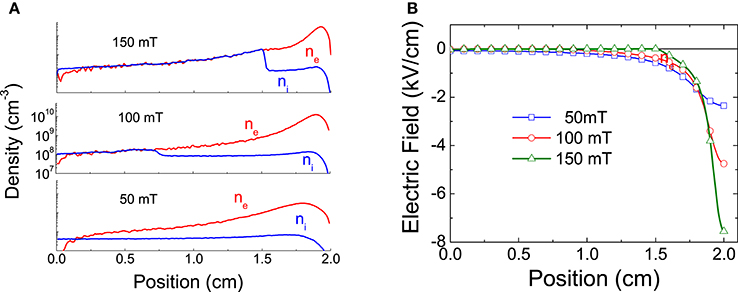
Figure 2. (A) distributions of the electron and ion densities between cathode and anode, and (B) of the electric field in a magnetized discharge in argon, 0.05 mTorr, 1 kV applied voltage and for three values of the magnetic field (perpendicular to the discharge axis). Results from a 1D Cartesian rectangular PIC MCC simulation.
The results of Figure 2 are steady state results i.e., the charged particle densities and electric field no longer evolve in time after a transient period whose duration depends on the initial conditions.
An order of magnitude of the sheath width can be obtained from a simple analytical treatment first derived by Kervalishvili and Zharinov [48] (see also Abolmassov et al. [18]). Neglecting the ion density in the anode sheath, assuming that the electron density in the sheath, nes, is constant and noting ds the sheath width, Poisson's equation gives an estimation of the electric field on the anode, Ea⧸ds = −enes⧸ε0 = −2Va⧸d2s (Va is the anode voltage). Using the classical collisional mobility and neglecting diffusion, the electron current density at the anode is: .
This current must be equal to the ion current density on the cathode jic (neglecting the secondary electron current at the cathode). Assuming that most of the electron impact ionization takes place in the electron sheath with a constant ionization frequency νi, we can write (d is the gap length):
The numerical values obtained with this expression of the electron sheath width are smaller than those obtained from the numerical simulations of Figure 2 because the assumption of a constant electron density in the sheath is not very good. Nevertheless, the analytical expression gives a good order of magnitude and provides a reasonable scaling. We see also that for a given applied voltage, the sheath width increases with decreasing magnetic field and that there is a critical value of the magnetic field below which ds ≥ d, i.e., the discharge plasma is non-neutral over the whole gap length. Note that the expressions above assume classical collisional electron transport, which is reasonable in the frame of this 1D model, but doubtful in a more realistic 2D situation (see below).
The 1D PIC MCC results above are steady state i.e., the space distributions of the plasma properties predicted by the simulations and plotted in Figure 2 no longer evolve on time scales much larger than the time constants of the problem. This is in contradiction with the recent theory developed by Abolmasov et al. [18]. This theory states that the instabilities observed in low pressure magnetron discharges are not of the diocotron type but are the results of periodic travel of the electron sheath through the discharge gap. The 1D PIC MCC simulations do not reproduce such oscillations.
1D simulations cannot describe the possible formation of non-uniformities in the azimuthal direction, so simulations in a 2D cylindrical geometry were performed. In the 2D simulations the electron sheath next to the anode was not stable and the sheath transformed into rotating electron vortices (see Figure 3). The vortices evolved in time on a time scale much longer than the rotation period.
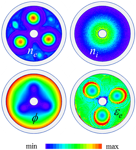
Figure 3. Distributions of the electron density, ne, ion density, ni, electric potential ϕ, and electron mean energy εe at a given time in a cylindrical magnetron (cathode and anode diameters 1 and 6 cm respectively); argon at 0.05 mTorr, applied voltage 2 kV, magnetic field 50 mT. The magnetron length is 10 cm and the end plates are biased at −100 V with respect to the cathode. The plots are linear, in the (min, max) ranges (0, 3 × 10¹⁵ m−3) for ne, (0, 0.2 × 10¹⁵ m−3) for ni, (−60, 2000 V) for ϕ, (0, 120 eV) for εe. The period of rotation of the structure is about 70 ns, on the order of E/B at the vortex location.
The three vortices of Figure 3 are relatively large and easily interact through their space charge potential. In the conditions of the figure, the self-organized structure of three electron vortices is stable for duration on the order of 10 μs only (the electron collision time in these conditions is on the order of 2 μs and the ionization time is about 5 μs). The number of electron vortices evolves in time and their size depend on the magnetic field intensity and on the electrode gap. At the instant represented in the figure, the size of the electron vortices is on the order of 1 cm. The ion density is azimuthally symmetric and is about 10 times smaller than the electron density in the vortices. The space charge of the electron vortices creates large potential perturbations (potential drop in the vortices) as can be seen on Figure 3. Electrons rotate inside the vortices and in the azimuthal direction due to E × B drift. The electron mean energy displayed in Figure 3 is rather large in these conditions due to the very large value of the reduced “effective field” [49–52] (reduced field that would give the same electron energy gain per unit time in the direction of the electric field, without magnetic field), which is on the order of (E⧸p)eff ≈ (E⧸p) ν⧸Ωe ≈ 1 kV/cm/torr). Electron vortices are also present for lower values of the effective field and electron mean energy. The orbits of the vortices are not perfectly stable and evolve in time. In the example of Figure 3, the three vortices rotate for a long time (10 μs) compared with the period of rotation (70 ns) before destabilization. Abrupt changes in the structure happen periodically and are associated with abrupt losses of electrons from the system. This can be seen on the sequence of Figure 4 which shows the electron density distribution in the gap at different times during the evolution of the vortex structure. The right part of Figure 4 shows the time evolution of the number of electrons in the system, during this sequence. Figure 5 also shows (but on a longer time scale) the time evolution of the number of electrons in the device, together with the variations of the electron current to the anode and to the end plates as a function of time. We see on Figure 4 at time indicated 2, that one of the electron vortices reaches the anode. This leads to an abrupt decrease of the number of electrons in the system, associated with an electron current pulse on the anode and followed by a complete redistribution of the electron density in the gap.
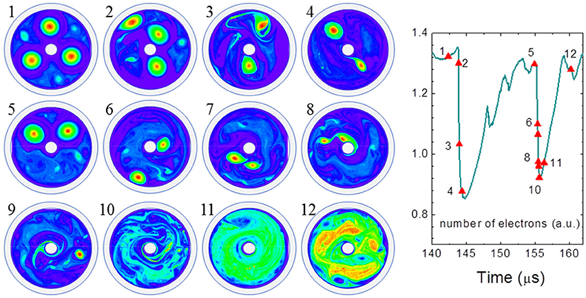
Figure 4. Left: particular sequence in the evolution of electron vortices in the conditions of Figure 3; Right: number of electrons as a function of time in the sequence (each time of the left plot is indicated by a triangle symbol). The (min, max) range is (0, 3 × 10¹⁵ m−3) except for times 11, and 12, 13, where it is respectively (0, 1.5 × 10¹⁵ m−3) and (0, 1015 m−3) (Same color bar as Figure 3).
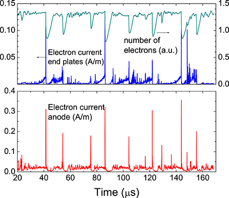
Figure 5. Electron current to the anode and to the end plates as a function of time in the conditions of Figures 3, 4. The variation with time of the total number of electrons in the magnetron is also plotted.
The two other vortices are first pushed toward the cathode (time 2), then the outer vortex, close to the anode, merges with one of the two others (times 2–3). The two remaining vortex then continue to evolve and grow (times 3–5) until each one touches one of the electrodes (time 6). They incompletely merge at time 7 and then the system evolves toward a more chaotic distribution of electron density (times 8–11). After some time the density reorganizes and a new system of well-defined electron vortices will emerge.
We see in Figure 5 that the electron current to the anode is composed of large pulses superimposed on a quasi-continuum. The continuum corresponds to the background density of electrons outside the vortices (typically 10 times smaller than in the vortices). These electrons slowly flow to the anode through collisional transport across the magnetic field. The pulses correspond to events such as those described above and apparent on Figure 4. The charged particle losses to the end plates in the direction of the magnetic field play an important role in the overall particle balance. An interesting feature is that although the end plates are biased at −100 V with respect to the cathode, there is a non-zero electron current to the end plates and electrons are also ejected in bursts to the end plates. It appears on Figure 5 that there is a clear correlation between the bursts of electron current to the end plates and the electron current pulses to the anode.
This is because each event (e.g., vortex reaching one electrode) induces a complete reorganization of the potential and an abrupt drop of the potential in the vortex leads to the ejection of electrons to the end plates (the minimum potential in the vortices in −60 V at the time of Figure 3, but this minimum evolves in time). We have also observed situations where the potential in a small region in a vortex or close to a vortex drops below the end plate potential, leading to a large and short electron current pulse to the end plates.
The presence of electron vortices in low pressure cylindrical magnetrons and Penning cells has been discussed in the literature mainly by N.A. Kervalishvili and his group on the basis of current and probe measurements [53–56]. Kervalishvili and his group inferred from their current and probe measurements the presence of the electron vortices and proposed a qualitative description of the formation, interaction, and dynamics of these vortices that is remarkably and strikingly consistent with the PICC MCC simulation results described above. Kervalishvili et al. suggested some possible mechanisms to explain the formation and stability of long-lived solitary vortices in these discharges [57], and discuss, in a more recent paper, the comparative properties of vortex structures in gas discharges and pure electron plasmas [58]. They also deduce from the measurements that the electron current measured on the end plates is due to the presence of “anomalously high energy electrons” that escape to the end plate when two vortices approach each other (the electrons are supposed to be able to accumulate energy in the direction parallel to the magnetic field because of collisions). The explanation provided by the model is slightly different but not inconsistent with Kervalishvili's interpretation: during the interaction and merging of two vortices, the potential can drop locally close or even below the end plate potential, leading to a short current pulse.
Rotating Spokes at Higher Pressure (>10−3 torr)
If the pressure is raised to around 1 mtorr and above in cylindrical magnetrons of diameter of a few cm, the ion density increases because of collisions while electron trapping by the magnetic field becomes less efficient, and a quasi-neutral plasma forms. The magnetron discharge is a glow discharge that can operate at much smaller pressure that non-magnetized glow discharges because of the electron confinement. In a non-magnetized glow discharge without positive column, part of the electrons and ions produced in the negative glow adjacent to the cathode sheath diffuse together toward the anode.
This ambipolar diffusion is associated with a potential maximum and a field reversal in the glow (see, e.g., Boeuf and Pitchford [59]). In a magnetized glow discharge the collisional electron mobility is smaller than the ion mobility and the sign of the electric field cannot reverse, at least in the context of a simple 1D model of the discharge. As illustrated in Figure 6, 1D PIC MCC simulations of a cylindrical magnetron (see also van der Straaten et al. [60], van der Straaten et al. [61], Boeuf and Chaudhury. [46]) predict that the electric field in the plasma is negative in the whole gap and increases to allow the generation of ions through ionization to ensure plasma quasineutrality and current continuity (note that small amplitude oscillations may develop in the 1D solutions as discussed in van der Straaten et al. [60], van der Straaten et al. [61] and the results of Figure 6 are integrated in time).
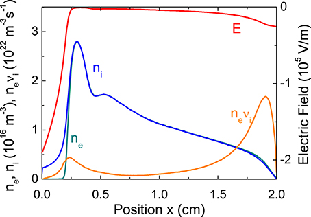
Figure 6. Distribution of charged particle densities, ionization rate, and electric field in a 2 cm gap magnetron discharge in argon, 10 mTorr, 400 V, 30 mT, secondary electron emission by ion impact 0.1. The cathode is at x = 0.
The 1D PIC MCC solution of Figure 6 is actually not stable in a 2D geometry and a 2D PIC MCC simulation gives a very different picture of the discharge as shown by Boeuf and Chaudhury [46] and discussed below. The large radial plasma electric field seen in Figure 6, which is necessary to draw the electron current to the anode in the 1D solution, does not form in the 2D solution and the system finds another way to carry the electron current to the anode. The fact that solutions of 1D models of the cylindrical magnetron may not be stable had been discussed by van der Straaten and Cramer [62] following their publications on 1D PIC MCC simulations [60, 61]. The work of Straaten and Cramer was a generalization of the theory of Simon [63], Hoh [64] who showed that in an E × B plasma, a situation where the plasma density gradient and electric field are in the same direction (as in Figure 6) is unstable. This instability (Simon-Hoh instability) is related to the fact that due to collisions, the E × B velocity of ions is lower than that of electrons. This causes a charge separation between electrons and ions and therefore the formation of a perturbed azimuthal electric field. It was shown later by Sakawa et al. [65], Sakawa and Joshi [66] that a similar type of instability (the modified Simon-Hoh instability) is also present in a collisionless plasma under conditions were the electrons are magnetized while the ions are not or are less magnetized (this also results in a lower E × B velocity of ions).
Figure 7 illustrates the 2D PICC MCC solutions for a magnetron discharge in the same conditions as the 1D solution of Figure 6. We see on this figure that the plasma properties are not azimuthally symmetric. The electric potential in the plasma presents an abrupt azimuthal drop which defines a sharp separation (that we call below the front of the instability, or the spoke) between two plasma regions. Ahead of the front in the azimuthal direction, the plasma potential is close to the anode potential (400 V). Behind the front the potential drops abruptly (about 10 V over 1–2 mm) and reaches a minimum 20 V below the anode potential. The potential then goes up slowly (over about 1/3 of the azimuthal direction) to values close to the anode potential.
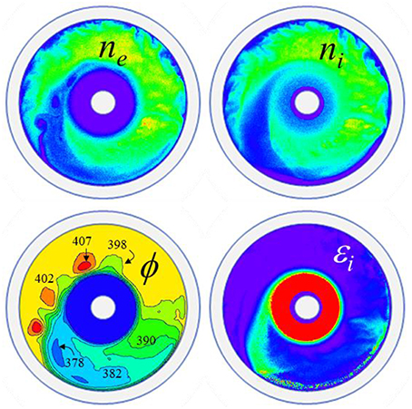
Figure 7. Distribution of the electron density, ne, ion density, ni, electric potential, ϕ, and ion mean energy εi at a given time of a steady state magnetron discharge in argon, 10 mTorr, applied voltage 400 V, magnetic field 30 mT. The cathode (inner cylinder) diameter is 1 cm and the anode diameter is 5 cm. The scales are linear and the (min, max) values are (0, 0.3 × 10¹⁶ m−3) for ne and ni, [370, 400 V] for ϕ (the blue region around the cathode is below 370 V and includes the cathode sheath), (0, 10 eV) for εi (mean energies much larger than 10 eV are reached in the cathode sheath –red region, with a maximum of up to 250 eV of the mean ion energy on the cathode surface). The structures appearing on these plots rotate clockwise in about 16 μs (Same color bar as Figure 3).
The region of lower potential behind the spoke is termed below as the “plasma structure.” The spoke and the whole plasma structure rotate around the cylindrical axis in about 16 μs. The potential drop in the front is associated with the formation of a double layer. Ions are accelerated azimuthally across the potential drop as can be seen on the distribution of the ion mean energy in Figure 7. Note that the maximum plasma density in these simulations is on the order of 3 × 10¹⁵ m−3, i.e., 10 times lower than in the 1D simulations because of the completely different electron transport from cathode to anode (note that there are typing errors in the units of the electron density and ionization rates in the captions to Figures 2,3 of Boeuf and Chaudhury [46]; the units should be 10 times lower than indicated in the captions).
The formation of the spoke allows a complete redistribution of the electron current in the plasma, very different from the simple radial current flow predicted by the 1D model of Figure 6. The abrupt potential drop in the front of the spoke generates a large, quasi-azimuthal electric field as can be inferred from the potential distribution of Figure 7 and is illustrated in Figure 8. This electric field (on the order of 5–10 kV/m) induces a large radial E × B velocity and associated E × B electron flux. It is interesting to note that the sheath associated with the electric field in the front is directly connected to the anode sheath as can be seen on Figure 8. The lower plasma potential region is surrounded by large electric field layers (large electric field in the anode sheath and in the spoke front, lower electric field in the back of the structure). This generates an E × B electron flow illustrated by the blue arrows of Figure 8. Note that the E × B flow is perpendicular to E and therefore parallel to the equipotential contours. We see that electrons flow from the end of the cathode sheath to the anode in the back of the plasma structure. The potential variations are much less abrupt in this region than in the front so the electron flux from cathode to anode is less intense than in the front but is distributed over a large region. When they reach the anode sheath, the electrons flow in the E × B direction along the sheath, some of them being captured by the anode due to collisional drift across it or because their Larmor radius is larger than the sheath. The electron flow along the anode sheath turns radially toward the cathode, following the equipotential lines at the location of the spoke, reaches the cathode sheath, follows the cathode sheath edge etc… In term of electron transport from cathode to anode these results can be summarized by saying that there is a large, localized electron flux from anode to cathode at the spoke front, and a smaller but more distributed electron flux from cathode to anode at the back of the cathode. To have a net flux from cathode to anode, the total electron flow in the back of the structure must be larger than in the front.
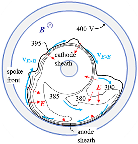
Figure 8. Diagram showing the directions of the electric field E and electron mean velocity and flux in the conditions of Figure 7. The equipotential lines in the plasma (between 380 V and the anode potential at 400 V) are also shown. The electron flux is mainly in the E × B direction, i.e., parallel to the equipotential lines (with a small component due to collisional drift in the direction opposite toE), i.e., parallel to the front in the spoke while the direction of the ion flux is close to the electric field direction, i.e., perpendicular to the spoke front in the spoke region.
To better understand the cross-field electron transport from cathode to anode we can measure, in the simulation, the electron current collected by a particular section of the anode as could be done in an experiment with a segmented anode. This current is shown in Figure 9. We see that the current collected by the anode segment is modulated in time, with a period equal to the period of rotation of the spoke. This current increases when the spoke reaches the anode segment and decreases as the spoke moves away from it. On the ionization rate displayed at three different times in Figure 9, one can see the larger ionization rate in the spoke region. The collected current passes through a maximum just after the spoke has reached the azimuthal position of the collector. This confirms that electrons flow to the anode due to the radial E × B transport induced by the azimuthal potential gradient in the back of the structure.
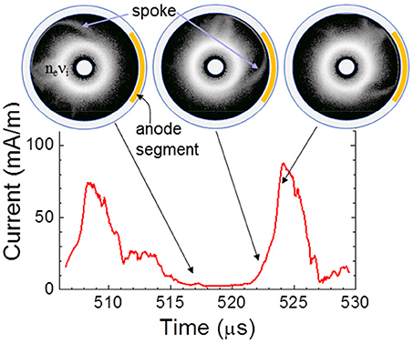
Figure 9. Electron current as function of time collected by a segment of the anode (indicated by an orange line on the right side of the anode). The distribution of the ionization rate (integrated over 200 ns) is also displayed at three different times (log scale, three decades, maximum 1022 m−3s−1, darker regions corresponds to lower ionization rates). The positions of the spoke front at the three times can be seen on the ionization rate plots.
We now focus on the properties of the plasma in the spoke. Figure 10 shows the distribution of charged particle densities and electric field in a direction perpendicular to the front, at a particular radial position. The plasma is strongly inhomogeneous and we see the formation of a double layer with a larger density of ions in the front (left of the figure) and a larger density of electrons in the back. The maximum electric field associated with the double layer is between 5 and 10 kV/m, corresponding to E⧸B drift velocities of a few 105 m/s. The ionization rate presents a maximum in the spoke front (as can be seen also in Figure 9).
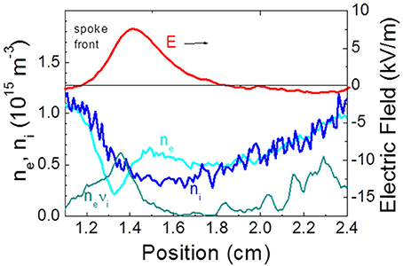
Figure 10. Distribution of the charged particle densities and electric field at a given radial position at the front of the spoke in the same conditions as Figure 7, showing the double layer and associated electric field. The ionization rate profile (neνi) is also shown (unit 2 × 10²⁰ m−3 s−1). The results are integrated in time over 100 ns.
The large E × B electron flow is in the back of the double layer, i.e., in the negative space charge region. Instabilities form in the spoke front, in the region of low electron density and are associated with the large E × B electron velocity along the azimuthal sheath. These instabilities, visible in Figures 7, 9, 11, travel at the E × B velocity and are likely to be two-stream instabilities. The decrease of the ion density from the front to the back is due to ion acceleration by the double layer electric field. The ion mean energy in the front reaches values on the order of 5 eV (Figure 7), about half of the potential in the front because of charge exchange collisions and of the fact that some ions are created by ionization in the front and do not see the whole potential drop. The velocity of argon ions at this energy is about Vi ≈ 5 × 10³ m/s and is consistent with the velocity of the rotating spoke (2πR⧸T with R ≈ 1 cmand T ≈ 15 μs), i.e., the rotation of the spoke is directly related to the ion acceleration through the double layer.
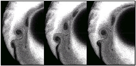
Figure 11. Distribution of the electron density (enlargement of the front region) at three successive times separated by 20 ns showing the two-stream instability in the spoke front. Darker regions correspond to lower electron densities (same conditions as Figure 7).
The properties of the rotating spoke as predicted by the PIC MCC simulations present striking similarities with the model proposed by Piel et al. [67] to explain the rotating spokes observed in the 1970s–1980s (see the reviews by Piel [34], Brennings [33]) in pulsed high-power homopolar E × B discharges studied in the context of fusion and also in relation with the concept of CIV. The CIV concept was introduced by Alfven in a model of the formation of the solar system. This model states that when a neutral gas cloud falls, due to the sun gravity, on a magnetized plasma, rapid ionization occurs and an ionization front (and a double layer) forms when the gas velocity reaches a critical value called the CIV. The falling gas is therefore ionized, is trapped by the magnetic field and is prevented from falling further in the gravitational field of the sun. It has been suggested that this mechanism can explain the formation of planets of different mass compositions at different distances from the sun. In our problem or in the studies of homopolar discharges, the gas is at rest and the ionization front is moving but the physics is similar. The basic idea of the CIV concept is that the double layer is sustained by ionization in the front. Electrons are trapped by the magnetic field and drift along the E × B direction while ions are accelerated by the double layer field, just as in Figure 10. To sustain ionization in the double layer, the potential drop must be on the order of the ionization potential of the gas, Ui, and a physical mechanism must transfer this energy to the electrons to allow ionization. The velocity of the ions accelerated by the double layer is therefore on the order of the CIV defined by where M is the ion mass. The mechanism by which the electrons gain energy from the double layer field has been the subject of a number of papers and theories summarized by Piel et al. [67]. One mechanism that was invoked to explain this energy transfer to the electrons was a two-stream instabilities due to the large E × B velocity of the electrons. This instability was supposed to provide the electron heating necessary for ionization in the front. In our 2D PIC MCC simulations an instability of the E × B electron flow in the front is clearly present (see the electron density and electric potential in the spoke front in Figure 7, and the enlargement of the region of instability at three different times in Figure 11) but the role of this instability in the collisionless heating of the electrons in the front is not easy to quantify.
As shown in Figure 8 the electron transport is complex and electrons flowing in the spoke front could equally well have gained energy by collisional transport across the cathode sheath, anode sheath, or even in the double layer field itself (as discussed in Boeuf and Chaudhury [46]). It is therefore difficult to conclude in our conditions that the potential drop in the spoke front should be equal to the ionization potential or that collisionless electron heating plays an important role. Nevertheless, the numerical results show that the potential drop in the front is not far from the ionization potential and the ion velocity and rotating spoke velocity are smaller but close to the CIV. Moreover, calculations performed with different ion masses (keeping the same electron and ion cross sections and changing artificially the ion mass) showed that the spoke velocity was directly related to the ion mass and varied roughly as M−1/2.
To conclude this section we can say that the 2D PIC MCC in this simple magnetron configuration provide very interesting results that seem closely related to the concepts of rotating spokes and CIV which were thoroughly discussed in the 1970s–1980s in the context of more complex homopolar discharge experiments or of Alfven theory of the solar system formation. We have however to keep in mind that these results are only two-dimensional and correspond to flute modes where the plasma is supposed to be uniform along the magnetic field. Numerical results not mentioned here also show that the spoke rotation is not always very regular, that the system can sometimes exhibit a m = 2 mode (two spokes) or transition between a m = 1 and m = 2 mode, or present a much less organized or more chaotic behavior. Due to computational limitations, the numerical results presented here have been obtained at relatively low plasma densities (less than 1010 m−3). It is not clear if the global physical picture of the rotating spoke provided by the simulations at these low densities would hold at much higher plasma densities (although we note that plasma density in the rotating spokes observed in homopolar discharges was two or three orders of magnitudes larger than in the present simulations). Further work is also needed to quantify clearly the role of the instability on the average electron transit time from cathode to anode, and to compare more systematically the “anomalous electron transport” predicted by the 2D simulations with the classical, collisional transport results provided by the 1D model (both in the neutral regime of section Electron Vortices at Low Pressure (<10−4 torr) and in the quasineutral regime described in this section).
Finally we must mention that a magnetron discharge is just one of many different ways of sustaining a magnetized plasma column. Many experiments and theoretical works have been devoted to the study of low temperature magnetized plasma columns sustained by electron beams [68, 69], by filaments, or by inductive sources or helicons [70]. Reports of the presence of rotating structures in these devices are numerous (see, e.g., evidence of rotating structures in the MISTRAL plasma column, shown by Laser Induced Fluorescence measurements [71]) but very little self-consistent modeling of these structures has been published.
Electron Cyclotron Drift Instability in a Hall Thruster Type Magnetic Barrier
We have seen in the section above on the “high pressure” regime of cylindrical magnetrons, that 1D PIC MCC simulations predict a large value of the electric field in the plasma to compensate for the low electron conductivity and ensure continuity of the current across the discharge. In a 2D treatment of the same problem, the radial electric field in the plasma collapses because the 1D solution is not stable and the plasma “organizes itself” in such a way that the electron current can flow to the anode without the presence of a large radial field. This shows that establishing a large electric field in the plasma by lowering the electron conductivity with a magnetic field barrier is not straightforward to achieve because “anomalous” transport across the magnetic field can be easily driven by instabilities or non-uniformities of the plasma and enhance the plasma conductivity.
Hall thrusters (Figure 12A) are very interesting examples of E × B devices where a large electric field can indeed be generated in the plasma due to the lowering of the plasma conductivity by a magnetic barrier (Figure 12B). The large electric field in the plasma is used to accelerate ions toward the outside of the thruster. The operating conditions are very sensitive to a number of parameters such as the dimensions of the plasma channel, the length of the magnetic barrier, the intensity of the magnetic field, the applied voltage, the gas flow rate etc… Moreover, Hall thrusters operate in a regime where the gas injected on the anode side is almost completely ionized by the electrons flowing from cathode to anode through the magnetic barrier. The gas density is therefore not constant but decreases from the anode to the exhaust plane and the plasma conductivity is not controlled simply by the magnetic field distribution, but also by the gas density distribution which is not imposed but is the self-consistent result of ionization. The electric field distribution in the plasma is thus related to the magnetic field distribution, plasma density profile, gas density profile and ionization rate distribution. Another important aspect of the strongly non-linear physics of a Hall thruster is that although a large electric field can be established in the plasma, meaning that the electron conductivity is successfully and significantly reduced in the magnetic barrier, models based on the classical theory of collisional conductivity fail to quantitatively reproduce the experimental observations.
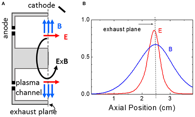
Figure 12. (A) Schematic of a Hall thruster. The plasma is generated between two concentric dielectric cylinders. The magnetic barrier is generated in the exhaust plane by a system of coils and a magnetic circuit; (B) axial profiles of the external radial magnetic field and of the calculated axial electric field (2D PIC MCC simulation, adapted from Adam et al. [42]) along the middle of the channel. The axial electric field is generated by the drop of electron conductivity in the magnetic barrier.
The classical conductivity associated with electron-neutral and electron-ion collisions is too low by one order of magnitude or more (see, e.g., Meezan et al. [72], Adam et al. [42] and references therein) to describe the electron current in the exhaust region of the thruster. This is the reason why Hall thruster models are still not predictive and the detailed design of these thrusters is still empirical.
A considerable research effort has been devoted to the study of the physical mechanisms that could be responsible for anomalous electron transport across the magnetic barrier in a Hall thruster. The identified possible mechanisms are: electron interaction with the walls (scattering, secondary electron emission), instabilities and turbulence (e.g., “rotating spokes,” high frequency drift instabilities, resistive instabilities, sheath instabilities coupled with the E × B drift, …). In the configuration of a Hall thruster, it seems natural to look for pure plasma instabilities but the experiments show that the electron current and plasma conductivity are also dependent on the wall material. Therefore, the role of electron-wall interactions on electron transport across the magnetic barrier cannot be neglected. Recent studies propose some combined effect of plasma instabilities and plasma-wall interaction [73, 74]. Reviewing the instabilities that could be responsible for anomalous electron transport in a Hall thruster is far beyond the scope of this paper. Oscillations in the 1 kHz–60 MHz frequency range are discussed by Choueiri [39] in a 2001 paper. A more recent review of the low frequency azimuthal instabilities can be found in the paper by Escobar and Ahedo [75] while the paper by Frias et al. [76] discusses and re-visits the fluid theory of long wavelength gradient drift instability. The effect of secondary electron emission from the channel walls of a thruster on electron transport and instabilities have been studied using particle simulations in a series of recent papers [77–81].
Since one of the purposes of this paper is to illustrate how PIC MCC simulation can help identify and understand instabilities in E × B devices, we focus below on a particular micro-turbulence in the mm scale that has been predicted by PIC MCC simulations [40–42, 73], observed by collective scattering experiments [28, 42, 82–84] and leads to an increase of electron conductivity consistent with the measurements. This instability is termed as “electron-cyclotron drift instability” and results from the resonant coupling between Bernstein electron modes and ion acoustic waves. This is a kinetic instability that had been studied theoretically [85] and simulated [86, 87] in the 1970s in the context of the propagation of shock waves perpendicular to a magnetic field and more recently in the context of Hall thrusters.
The dispersion relation for the electron-cyclotron drift instability [41, 84] predicts a wave vector ky in the direction E × B close to:
where is the electron drift velocity and n is an integer. This corresponds to very short wavelengths close to or below the electron gyroradius. The Bernstein waves at frequencies multiple of Ωe are Doppler-shifted toward low frequency by the high drift velocity Vd and can couple with the ion acoustic wave, which gives rise to the instability.
The presence of electron-cyclotron drift instabilities has been predicted by 2D PIC MCC simulations in the axial—azimuthal plane [40, 42] or in the radial—azimuthal plane [73] (these 2D simulations were limited to a relatively short length in the azimuthal direction and assuming periodic boundary conditions). The 2D PIC MCC simulations in the conditions of a Hall thruster are very cumbersome because of the large plasma density and the computation time is large even with implicit and parallelized codes. It seems therefore natural to try to use simpler kinetic simulations of the electron-cyclotron drift instability to infer quantitative information on cross-field electron transport that could be used in simpler fluid or hybrid models. This can be done with 1D particle models.
The goal of the results presented and discussed below is twofold:
(1) To illustrate the fact that the electron-cyclotron drift instability is present under the large E × B drift velocities of Hall thrusters and appear very easily in 1D PIC MCC simulations.
(2) To stimulate critical thinking and discussions regarding the feasibility or relevance of using such kinetic simulations to deduce macroscopic parameters to be used in fluid models of electron transport in Hall thrusters.
Ducrocq et al. [41] developed a 1D Particle-In-Cell simulation in the E × B direction to study the effect of the distortion of the electron velocity distribution function on the instability predicted by the theoretical dispersion relation (the theoretical dispersion of the electron-cyclotron drift instability is based on the assumption of a Maxwellian electron distribution function.). The accelerating electric field, the magnetic field and the plasma density were given and the 1D PIC simulation was used to study the collisionless development of the instability in the direction perpendicular to the electric and magnetic fields. Ducrocq et al. showed that the instability evolves into a comb of unstable modes developing for each ky Vd = nΩe with a maximum growth rate shifting to decreasing values of ky as the distribution function is deformed by the instability. The instability was saturated in these simulations only because of the finite length of the simulation domain in the azimuthal direction. One can understand that there is no real (i.e., not due to the limited size of the simulation domain) saturation of the instability in such simulation since the electrons only gain energy in the applied field E0 during their transport across the magnetic field (this transport being made possible by the instability). Therefore, such simulation cannot provide any information on macroscopic transport properties of the electrons such as a cross-field mobility.
In order to try to define and quantify the anomalous mobility associated with the electron-cyclotron drift instability, we performed 1D PIC simulations similar to those of Ducrocq et al. [41] but including some physical effects that lead to a saturation of the instability. In a real device, the saturation of the instability can occur because of the finite length of the acceleration channel, because of electron collisions with neutral atoms or interaction with the walls. The PIC MCC simulations described below include electron-atom collisions and assume a finite length of the acceleration channel.
We consider an initially uniform neutral plasma of density n0 in a given, constant electric field E0 (the axial electric field of a Hall thruster parallel to the x direction) and with a given, constant gas density ng, considered as a parameter of the simulation. A magnetic field B0 is applied perpendicularly to the electric field, in the z direction. The plasma is supposed to be uniform in the directions parallel to the electric and magnetic fields, and we look for the development of instabilities in the E0 × B0 direction (the “azimuthal direction,” y). Electrons and ions are subject to the imposed field E0 and B0 and to the self-consistent space charge field Ey associated with the instability (if any) in the E0 × B0 direction and deduced from the solution of Poisson's equation in this direction. The trajectories of electrons and ions under the effect of these fields and of collisions with neutrals are integrated during each time step. At the end of each time step, the charged particle densities along the E0 × B0 direction can be deduced from the charged particle positions, and the electric field Ey is re-calculated, as in standard PIC MCC simulations. We consider a simulation length Ly in the y direction, with periodic boundary conditions (this is a way to account for the fact that the E0 × B0 direction is closed—the total azimuthal length of a real thruster is too long to be taken into account in the simulation). To keep the average plasma density n0 constant, ionizing collisions are treated as excitation (the number of charged particles in the simulation stays constant). Finally the charged particles are followed over a finite acceleration length, Lx, supposed to be equal to 1 cm (this is consistent with the 2D simulation of Figure 12B). When the charged particles reach the end of the acceleration region, a new particle is injected at the other end according to a Maxwellian distribution of temperature 2 eV for electrons and 0.1 eV for ions, and at a random position along the y direction.
Figure 13A shows an example of distribution of the azimuthal electric field and charged particle density profiles obtained at steady state under conditions where the instability saturates (the system reached steady state in about 1 μs). The amplitude of the azimuthal electric field oscillations is very large, on the same order as the imposed axial electric field E0. The wave is associated with a large plasma polarization and with large fluctuations of the plasma density whose amplitude is more than 10% of the average plasma density. The ion phase space of Figure 13B shows the ion trapping in the azimuthal wave potential and the high velocity ions traveling with the wave (Landau effect). The wave in Figure 13A exhibits a well-defined period with a wavelength on the order of 1 mm. The wave velocity is about 5–10 km/s which gives, with a wavelength of 1 mm, a wave frequency in the 10 MHz range.
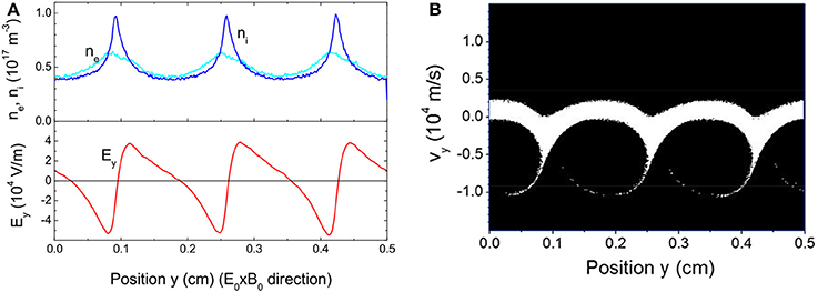
Figure 13. (A) Example of electron-cyclotron drift instability obtained with a 1D PIC MCC simulation. The charged particle densities and electric field distributions are plotted along the azimuthal direction (only a finite length Ly = 5 mm of this direction is simulated, with periodic boundary conditions. The given axial electric field and radial magnetic field are 2 × E0 = 104 V/m and B0 = 2 × 10⁻² T. The average plasma density, n0 is 5 × 10¹⁶ m−3, and the xenon gas density is ng = 1.6 1020 m−3 (0.005 torr at 300 K). The length of the acceleration region is Lx = 1 cm. The instability is saturated by electron-neutral collisions and by the finite acceleration length, and steady state is reached in about 1 μs; (B) Phase diagram (vy, y) of the ions along the azimuthal direction showing ion trapping in the wave potential and Landau absorption (conditions of Figure 13A). The ions are collisionless and unmagnetized in this simulation.
During the time evolution to steady state, the instability actually first forms (in about 100 ns) with a smaller wavelength. As the electron energy distribution function (EEDF) is modified by the instability and by collisions (the electron-neutral collision frequency is on the order of 3 × 10⁷ s−1 for the conditions of Figure 13) the wave number shifts to lower values. This is illustrated in Figure 14A and is consistent with the results of Ducrocq et al. [41].
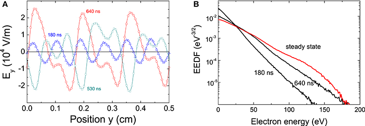
Figure 14. (A) Distribution of the azimuthal wave electric field at different times before the steady state of Figure 13A is reached (same conditions as Figure 13); (B) electron energy distribution function (EEDF) at three different times in the same conditions.
Figure 14B shows the deformation of the EEDF which is coupled to the development of the instability. The calculated electron temperature at steady state is 25 eV. The electron mobility can also be deduced from these calculations and is equal to 3 m2/V/s, to be compared with the classical collisional mobility which is about 0.9 m2/V/s in these conditions.
From simulations such as those described in Figures 13, 14 and provided that a steady state is reached, different macroscopic parameters (e.g., the cross-field electron mobility) can be deduced for the set of parameters used in the simulation: accelerating electric field E0, external magnetic field B0, gas density ng, plasma density n0.
The results of the simulations can be summarized as follows. For very low plasma densities or in the limit of zero plasma density no significant azimuthal wave develops and the electron mobility tends to the classical, collisional mobility (circle symbols of Figure 15). For a non-zero plasma density and for given E0 and B0, if the gas density is large (pressure above about 0.1 torr) a steady state solution is reached, with no instability and with an electron mobility also close to the classical, collisional mobility. When the gas density decreases but is still sufficiently large, instabilities develop but the space averaged electron distribution function reaches a steady state corresponding to a global balance between energy gain due to the applied electric field E0, and losses due to collisions.
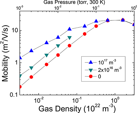
Figure 15. Calculated steady state cross-field mobility as a function of xenon gas density for different values of the average plasma density n0, and for E0 = 2 × 10⁴ V/m and B0 = 2 × 10⁻²T. The circle symbols corresponds to the classical cross-field electron mobility (no instability), obtained for low plasma densities, and the triangle symbols correspond to the electron mobility enhanced by the instability for n0 = 2 × 10¹⁶ m−3 and n0 = 1017 m−3. These results show that the anomalous mobility due to the electron-cyclotron drift instability is a strong function of the plasma density.
From the simulation results we can try to infer a qualitative understanding of the mechanisms leading to cross-field electron transport in the instability. Adam et al. suggested [40] that the stochastic motion of electrons in the wave field is responsible for the non-collisional electron transport. Some electrons trajectories can be resonant with the wave, leading to sudden jumps in the electron velocities that can have the same effect as collisions. Similar effects had been described by Karney [88, 89] in the context of ion heating by a monochromatic lower hybrid wave.
The observation of electron trajectories in our 1D PIC MCC simulations lead to a simpler conclusion. We find that resonant effects are not dominant and are not needed to explain electron transport across the magnetic field. The electrons trajectories are strongly deformed by the wave field and elongated in the direction parallel to E0. This is globally equivalent to a significant increase of the electron Larmor radius, i.e., to a lowering of the magnetic field and therefore to an increase of the electron mobility. Note that with this interpretation, collisions (or scattering with the walls) are still necessary to explain transport. The effect of the wave is just to increase the mobility by modifying the electron trajectories.
The description above of electron transport in a magnetic barrier under conditions close to those of a Hall thruster is clearly oversimplified since it neglects any effect of gradients (of electron density, magnetic field, gas density) in the axial direction and assumes a constant axial electric field E0. The concept of local mobility is of course questionable in the conditions of Hall thrusters: the acceleration region may be too short to reach an equilibrium between momentum or energy gain and losses, the gas density can be very low in this region at the moment of peak current [40, 90], etc…
Nevertheless, this description may be useful because it provides approximate quantitative information on how the electron-cyclotron drift instability modifies the electron mobility under conditions where such a mobility can be defined, and on how this mobility depends on parameters such as gas density and plasma density. For example, the strong dependence of the anomalous mobility on the plasma density is clearly shown by the simulations of Figure 15. Engineering models of Hall thrusters cannot be based on PIC MCC simulations and even though, strictly speaking, the concept of mobility may be not fully relevant, simpler models using this concept can be useful if the anomalous mobility can be scaled with relevant parameters (gas density, magnetic field, plasma density) and is not only a simple adjustable parameter [90–92]. We conclude from the simulations that if the concept of anomalous mobility is to be used in a fluid model of electron transport in Hall thrusters, and if the dominant source of anomalous transport is the electron-cyclotron drift instability, this anomalous electron mobility should be strongly dependent on the plasma density. The results above or some improved versions of these results (e.g., including the effect of wall scattering etc…) could provide a scaling of the anomalous mobility with the parameters (electric and magnetic fields, gas density, plasma density) that is more satisfactory than a simple empirical adjustment of the mobility.
Although the simulations show that the electron cyclotron drift instability easily forms and has a large growth rate, it is very likely (as the formidable literature on this topic indicates) that it co-exists with other types of instabilities that can also contribute to anomalous transport. The difficulty in Hall thruster research is to assess what is the dominant mechanism and how particular properties of the thruster (magnetic field distribution and gradients, channel dimensions etc…) can affect or change the dominant mechanism of cross-field transport.
Concluding Remarks
We have illustrated in this paper the question of electron transport in three typical but simplified E × B configurations of low temperature plasma sources on the basis of results from PIC-MCC simulations. With the help of the simulations, we have shown evidence of the formation of electron vortices in the conditions of low pressure magnetron discharges (typical of Penning or magnetron gages), we have reported and described the formation of rotating spokes and its contribution to electron transport in cylindrical magnetron discharges in the 10 mtorr range, and we have discussed the possible role of an azimuthal electron-cyclotron drift instability in the anomalous transport of electrons through a magnetic barrier in the presence of a large perpendicular electric field (and large Hall current). The physics involved in these devices is extremely rich and complex, and it clear from the discussions of the results that despite decades of research effort our understanding of this physics is still poor. The examples shown in this paper prove that particle simulations can be an extremely powerful tool to unravel some of the mysteries of electron transport in low temperature E × B devices. The simulations of steady state discharge devices is still difficult even in two-dimensions and for plasma densities larger than 1016 m−3 and dimensions of a few cm. Two approaches are equally valuable and should be developed more extensively in the future: (1) use of PIC MCC simulations under simplified conditions to get a better insight in the physics and to help building simpler models, (2) high performance computing with the development of massively parallel PICC MCC simulation tools that can address more realistic problems in term of plasma density and device geometry.
Conflict of Interest Statement
The author declares that the research was conducted in the absence of any commercial or financial relationships that could be construed as a potential conflict of interest.
References
1. Hooper EB. A review of reflex and penning discharges. Adv Electronics Electron Phys. (1969) 27:295–343. doi: 10.1016/S0065-2539(08)60040-2
2. Redhead PA. Instabilities in crossed-field discharges at low pressures. Vacuum (1988) 38:901–6. doi: 10.1016/0042-207X(88)90489-7
3. Keidar M, Beilis II. Electron transport phenomena in plasma devices with E×B drift. IEEE Trans Plasma Sci. (2006) 34:804–14. doi: 10.1109/TPS.2006.874852
4. Abolmasov SN. Physics and engineering of crossed-field discharge devices. Plasma Sources Sci Technol. (2012) 21:035006. doi: 10.1088/0963-0252/21/3/035006
5. Schuurman W. Investigation of a low pressure penning discharge. Physica (1967) 36:136–60. doi: 10.1016/0031-8914(67)90086-9
6. Phillips C. The action of magnetised electrodes upon electrical discharge phenomena in rarefied gases. Proc R Soc (Lond). (1898) 64:172–6. doi: 10.1098/rspl.1898.0088
7. Penning F. The spark discharge in low pressure between coaxial cylinders in an axial magnet field. Physica (1936) 3:873–84. doi: 10.1016/S0031-8914(36)80313-9
8. Penning F. A new manometer for low gas pressures especially between 10(-3) and 10(-5) mm. Physica (1937) 4:71–5. doi: 10.1016/S0031-8914(37)80123-8
9. Musil J, Baroch P, Vlčk J, Nam KH, Han JG. Reactive magnetron sputtering of thin films: present status and trends. Thin Solid Films (2005) 475:208–18. doi: 10.1016/j.tsf.2004.07.041
10. Safi I. Recent aspects concerning DC reactive magnetron sputtering of thin films: a review. Surf Coat Technol. (2000) 127:203–19. doi: 10.1016/S0257-8972(00)00566-1
11. Vlčk J, Pajdarova J, Musil J. Pulsed dc magnetron discharges and their utilization in plasma surface engineering. Contrib Plasma Phys. (2004) 44:426–36. doi: 10.1002/ctpp.200410083
12. Bradley JW, Welzel T. Physics and phenomena in pulsed magnetrons: an overview. J Phys D Appl Phys. (2009) 42:093001. doi: 10.1088/0022-3727/42/9/093001
13. Gudmundsson JT, Brenning N, Lundin D, Helmersson U. High power impulse magnetron sputtering discharge. J Vac Sci Technol A (2012) 30:030801. doi: 10.1116/1.3691832
14. Kaufman HR, Robinson RS, Seddon RI. End-Hall ion source. J Vac Sci Technol. (1987) 5:2081. doi: 10.1116/1.574924
15. Oudini N, Hagelaar GJM, Boeuf JP, Garrigues L. Physics and modeling of an end-Hall (gridless) ion source. J Appl Phys. (2011) 109:073310. doi: 10.1063/1.3572053
16. Oudini N, Garrigues L, Hagelaar GJM, Boeuf JP. Numerical study of the characteristics of the ion and fast atom beams in an end-Hall ion source. J Appl Phys. (2012) 112:073310. doi: 10.1063/1.4759314
17. Morozov AI. The conceptual development of stationary plasma thrusters. Plasma Phys Rep. (2003) 29:235–50. doi: 10.1134/1.1561119
18. Abolmasov SN, Samukawa S, Bizyukov AA. Theory of instabilities in crossed-field discharges at low pressures. Phys Plasmas (2007) 14:093501. doi: 10.1063/1.2768022
20. Mac Farlane C, Hay H. Wave propagation in a slipping stream of electron - small amplitude theory. Proc R Soc Lond. (1950) B63:409–27.
21. Levy RH. Diocotron instability in a cylindrical geometry. Phys Fluids (1965) 8:1288–95. doi: 10.1063/1.1761400
22. Levy RH. Computer experiments on low-density crossed-field electron beams. Phys Fluids (1968) 11:766–71. doi: 10.1063/1.1691997
23. Webster H. Breakup of hollow electron beams. J Appl Phys. (1955) 26:1386–7. doi: 10.1063/1.1721916
24. Malmberg JH, deGrassie JS. Properties of nonneutral plasma. Phys Rev Lett. (1975) 35:577–80. doi: 10.1103/PhysRevLett.35.577
25. Driscoll CF, Fine KS. Experiments on vortex dynamics in pure electron plasmas. Phys Fluids (1990) B2:1359–66. doi: 10.1063/1.859556
26. Driscoll CF, Jin DZ, Schecter DA, Dubin DHE. Vortex dynamics of 2D electron plasmas. Physica C (2002) 369:21–7. doi: 10.1016/S0921-4534(01)01216-3
Pubmed Abstract | Pubmed Full Text | CrossRef Full Text | Google Scholar
27. Bilyk O, Holík M, Marek A, Kudrna P, Tichy M, Behnke JF. Fluctuations of the magnetically-supported dc discharge in coaxial configuration. Vacuum (2004) 76:437–45. doi: 10.1016/j.vacuum.2004.06.001
28. Tsikata S, Lemoine N, Pisarev V, Gresillon DM. Dispersion relations of electron density fluctuations in a Hall thruster plasma, observed by collective light scattering. Phys Plasmas (2009) 16:033506. doi: 10.1063/1.3093261
29. Pal AR, Chutia J, Bailung H. Observation of instability in presence of E×B flow in a direct current cylindrical magnetron discharge plasma. Phys Plasmas (2004) 11:4719–26. doi: 10.1063/1.1792283
30. Brenning N, Lundin D, Minea T, Costin C, Vitelaru C. Spokes and charged particle transport in HiPIMS magnetrons. J Phys D Appl Phys. (2013) 46:084005. doi: 10.1088/0022-3727/46/8/084005
31. Winter J, Hecimovic A, de los Arcos T, Böke M, Schulz-von der Gathen V. Instabilities in high-power impulse magnetron plasmas: from stochasticity to periodicity. J Phys D Appl Phys. (2013) 46:084007. doi: 10.1088/0022-3727/46/8/084007
32. Anders A, Ni P, Rauch A. Drifting localization of ionization runaway: unraveling the nature of anomalous transport in high power impulse magnetron sputtering. J Appl Phys. (2012) 111:053304. doi: 10.1063/1.3692978
33. Brenning N. Review of the CIV phenomenon. Space Sci Rev. (1992) 59:209–314. doi: 10.1007/BF00242088
34. Piel A. Review of laboratory experiments on Alfven's critical ionization velocity. Adv Space Res. (1990) 10:7–16. doi: 10.1016/0273-1177(90)90267-4
35. Janes CS, Lowder RS. Anomalous electron diffusion and ion acceleration in a lowdensity plasma. Phys Fluids (1966) 9:1115–23. doi: 10.1063/1.1761810
36. McDonald M, Gallimore S. Rotating spoke instabilities in Hall thrusters. IEEE Trans Plasma Sci. (2011) 39:2952–3. doi: 10.1109/TPS.2011.2161343
37. Ellison CL, Raitses Y, Fisch NJ. Cross-field electron transport induced by a rotating spoke in a cylindrical Hall thruster. Phys Plasmas (2012) 19:013503. doi: 10.1063/1.3671920
38. Jorns BA, Hofer RR. Plasma oscillations in a 6-kW magnetically shielded Hall thruster. Phys Plasmas (2014) 21:053512. doi: 10.1063/1.4879819
39. Choueiri E. Plasma oscillations in Hall thrusters. Phys Plasmas (2001) 8:1411–26. doi: 10.1063/1.1354644
40. Adam JC, Héron A, Laval G. Study of stationary plasma thrusters using two-dimensional fully kinetic simulations. Phys Plasmas (2004) 11:295–305. doi: 10.1063/1.1632904
41. Ducrocq A, Adam JC, Héron A, Laval G. High-frequency electron drift instability in the cross-field configuration of Hall thrusters. Phys Plasmas (2006) 13:102111.
42. Adam JC, Boeuf JP, Dubuit N, Dudeck M, Garrigues L, Gresillon D, et al. Physics, simulation and diagnostics of Hall effect thrusters. Plasma Phys Control Fusion (2008) 50:124041. doi: 10.1088/0741-3335/50/12/124041
43. Boeuf JP, Chaudhury B, Garrigues L. Physics of a magnetic filter for negative ion sources. I. Collisional transport across the filter in an ideal, 1D filter. Phys Plasmas (2012) 19:113509. doi: 10.1063/1.4768676
44. Boeuf JP, Claustre J, Chaudhury B, Fubiani G. Physics of a magnetic filter for negative ion sources. II. E x B drift through the filter in a real geometry. Phys Plasmas (2012) 19:113510. doi: 10.1063/1.4768804
45. Phelps database. Available online at: http://www.lxcat.laplace.univ-tlse.fr. (retrieved August 9, 2013)
46. Boeuf JP, Chaudhury B. Rotating instability in low-temperature magnetized plasmas. Phys Rev Lett. (2013) 111:155005. doi: 10.1103/PhysRevLett.111.155005
Pubmed Abstract | Pubmed Full Text | CrossRef Full Text | Google Scholar
47. Siglo database. Available online at: http://www.lxcat.laplace.univ-tlse.fr. (retrieved August 9, 2013)
48. Kervalishvili NA, Zharinov AV. Characteristics of low pressure discharge in a transverse magnetic field. Sov J Plasma Phys. (1966) 10:1682–7.
49. Tonks L. Drift of ions and electrons in a magnetic field. Phys Rev. (1937) 51:744–7. doi: 10.1103/PhysRev.51.744
50. Tonks L, Allis W. Plasma electron drift in a magnetic field with a velocity distribution function. Phys Rev. (1937) 52:710–3.
51. Heylen AED. Electrical ionisation and breakdown of gases in a crossed magnetic field. IEE Proc. (1980) 127A:221–44.
52. White RD, Robson ER, Ness KF. On approximations involved in the theory of charged particle transport in gases in electric and magnetic fields at arbitrary angles. IEEE Trans Plasma Sci. (1999) 27:1249–53. doi: 10.1109/27.799800
53. Kervalishvili NA. Rotational instability of a charged plasma in crossed fields and generation of electrons of anomalously high energy. Sov J Plasma Phys. (1989) 15:98–102.
54. Kervalishvili NA. Rotating regular structures in a charged plasma in crossed electric and magnetic fields. Sov J Plasma Phys. (1989) 15:211–2.
55. Kervalishvili NA. Evolution of non-linear structures in charged plasmas in crossed fields. Sov J Plasma Phys. (1989) 15:436–7.
56. Kervalishvili NA. Electron vortices in a nonneutral plasma in crossed EXH fields. Phys Lett A (1991) 157:391–4. doi: 10.1016/0375-9601(91)90875-9
57. Kervalishvili NA, Kervalishvili G. The mechanism of stability of long-lived, self-organized solitary vortex in nonenutral electron plasma. J Georgian Geophys Soc. (1999) 4B:115–23.
58. Kervalishvili NA. Formation and dynamics of vortex structures in pure and gas-discharge nonneutral collisionless electron plasmas. J Georgian Geophys Soc. (2012) 15B:120–36.
59. Boeuf JP, Pitchford LC. Field reversal in the negative glow of I I a DC glow discharge. J Phys D Appl Phys. (1995) 28:2083. doi: 10.1088/0022-3727/28/10/013
60. van der Straaten T, Cramer T, Falconer I, James B. The cylindrical DC magnetron discharge: I. Particle-in-cell simulation. J Phys D Appl Phys. (1998) 31:177–90.
61. van der Straaten TA, Cramer NF, Falconer I, James B. The cylindrical DC magnetron discharge: II. The negative space charge mode. J Phys D Appl Phys. (1998) 31:191–206. doi: 10.1088/0022-3727/31/2/005
62. van der Straaten TA, Cramer NF. Transverse electric field and density gradient induced instabilities in a cylindrical magnetron discharge. Phys Plasmas (2000) 7:391. doi: 10.1063/1.873808
63. Simon A. Instability of a partially ionized plasma in crossed electric and magnetic fields. Phys Fluids (1963) 6:382–6. doi: 10.1063/1.1706743
64. Hoh FC. Instability of penning-type discharges. Phys Fluids (1963) 6:1184–91. doi: 10.1063/1.1706878
65. Sakawa Y, Joshi C, Kaw P, Jain V, Johnston T, Chen F, et al. Nonlinear evolution of the modified Simon-Hoh instability via a cascade of sideband instabilities in a weak beam plasma system. Phys Rev Lett. (1992) 69:85–8. doi: 10.1103/PhysRevLett.69.85
Pubmed Abstract | Pubmed Full Text | CrossRef Full Text | Google Scholar
66. Sakawa Y, Joshi C. Growth and nonlinear evolution of the modified Simon-Hoh instability in an electron beam-produced plasma. Phys Plasmas (2000) 7:1774–80. doi: 10.1063/1.873998
67. Piel A, Möbius E, Himmel G. The influence of the plasma inhomogneity on the critical velocity phenomenon. Astrophys Space Sci. (1980) 72:211–21. doi: 10.1007/BF00642180
68. Jaeger S, Pierre T, Rebont C. Direct observation of a cross-field current-carrying plasma rotating around an unstable magnetized plasma column. Phys Plasmas (2009) 16:022304. doi: 10.1063/1.3076931
69. Gravier E, Brochard F, Bonhomme G, Pierre T, Briancon JL. Low-frequency instabilities in a laboratory magnetized plasma column. Phys Plasmas (2004) 11:529–37.
70. Franck CM, Grulke O, Stark A, Klinger T, Scime EE, Bonhomme G. Measurements of spatial structures of different discharge modes in a helicon source. Plasma Sources Sci Technol. (2005) 14:226–35. doi: 10.1088/0963-0252/14/2/003
71. Rebont C, Claire N, Pierre T, Doveil F. Ion velocity distribution function investigated inside an unstable magnetized plasma exhibiting a rotating nonlinear structure. Phys Rev Lett. (2011) 106:225006. doi: 10.1103/PhysRevLett.106.225006
Pubmed Abstract | Pubmed Full Text | CrossRef Full Text | Google Scholar
72. Meezan N, Hargus W, Cappelli M. Anomalous electron mobility in a coaxial Hall discharge plasma. Phys Rev E (2001) 63:026410. doi: 10.1103/PhysRevE.63.026410
Pubmed Abstract | Pubmed Full Text | CrossRef Full Text | Google Scholar
73. Heéron A, Adam JC. Anomalous conductivity in Hall thrusters: effects of the non-linear coupling of the electron-cyclotron drift instability with secondary electron emission of the walls. Phys Plasmas (2013) 20:082313. doi: 10.1063/1.4818796
74. Frias W, Smolyakov AI, Kaganovich ID, Raitses Y. Wall current closure effects on plasma and sheath fluctuations in Hall thrusters. Phys Plasmas (2014) 21:062113. doi: 10.1063/1.4885093
75. Escobar D, Ahedo E. Low frequency azimuthal stability of the ionization region of the Hall thruster discharge. I. Local analysis. Phys Plasmas (2014) 21:043505. doi: 10.1063/1.4870963
76. Frias W, Smolyakov AI, Kaganovich ID, Raitses Y. Long wavelength gradient drift instability in Hall plasma devices. I. Fluid theory. Phys Plasmas (2012) 19:072112. doi: 10.1063/1.4736997
77. Kaganovich ID, Raitses Y, Sydorenko D, Smolyakov A. Kinetic effects in a Hall thruster discharge. Phys Plasmas (2007) 14:057104. doi: 10.1063/1.2709865
78. Sydorenko D, Kaganovich I, Raitses Y, Smolyakov A. Breakdown of a space charge limited regime of a sheath in a weakly collisional plasma bounded by walls with secondary electron emission. Phys Rev Lett. (2009) 103:145004. doi: 10.1103/PhysRevLett.103.145004
Pubmed Abstract | Pubmed Full Text | CrossRef Full Text | Google Scholar
79. Campanell MD, Khrabrov AV, Kaganovich ID. General cause of sheath instability identified for low collisionality plasmas in devices with secondary electron emission. Phys Rev Lett. (2012) 108:235001. doi: 10.1103/PhysRevLett.108.235001
Pubmed Abstract | Pubmed Full Text | CrossRef Full Text | Google Scholar
80. Campanell MD, Khrabrov AV, Kaganovich ID. Absence of Debye sheaths due to secondary electron emission. Phys Rev Lett. (2012) 108:255001. doi: 10.1103/PhysRevLett.108.255001
Pubmed Abstract | Pubmed Full Text | CrossRef Full Text | Google Scholar
81. Smolyakov AI, Frias W, Kaganovich ID, Raitses Y. Sheath-induced instabilities in plasmas with ExB drift. Phys Rev Lett. (2013) 111:115002. doi: 10.1103/PhysRevLett.111.115002
Pubmed Abstract | Pubmed Full Text | CrossRef Full Text | Google Scholar
82. Tsikata S, Honore C, Gresillon D, Lemoine N. Collective light scattering for the study of fluctuations in magnetized plasmas: the Hall thruster case study. Contrib Plasma Phys. (2011) 51:119–25. doi: 10.1002/ctpp.201000057
83. Tsikata S, Honore C, Gresillon D. Collective Thomson scattering for studying plasma instabilities in electric thrusters. J Instrum. (2013) 8:C10012. doi: 10.1088/1748-0221/8/10/C10012
84. Cavalier J, Lemoine N, Bonhomme G, Tsikata S, Honore C, Gresillon D. Hall thruster plasma fluctuations identified as the E x B electron drift instability: modeling and fitting on experimental data. Phys Plasmas (2013) 20:082107. doi: 10.1063/1.4817743
85. Gary SP, Sanderson JJ. Longitudinal waves in a perpendicular collisionless plasma shock - I. Cold ions. J Plasma Phys. (1970) 4:739–60. doi: 10.1017/S0022377800005390
86. Forslund D, Morse R, Nielson C. Electron cyclotron drift instability. Phys Rev Lett. (1970) 25:1266–70. doi: 10.1103/PhysRevLett.25.1266
87. Forslund D. Electron cyclotron drift instability and turbulence. Phys Fluids (1972) 15:1303–18. doi: 10.1063/1.1694082
88. Karney C. Stochastic ion heating by a lower hybrid wave. Phys Fluids (1978) 21:1584–99. doi: 10.1063/1.862406
89. Karney C. Stochastic ion heating by a lower hybdrid wave: II. Phys Fluids (1979) 22:2188–209. doi: 10.1063/1.862512
90. Boeuf J, Garrigues L. Low frequency oscillations in a stationary plasma thruster. J Appl Phys. (1998) 84:3541–54. doi: 10.1063/1.368529
91. Hagelaar GJM, Bareilles J, Garrigues L, Boeuf JP. Role of anomalous electron transport in a stationary plasma thruster simulation. J Appl Phys. (2003) 93:67–75. doi: 10.1063/1.1527218
Keywords: magnetized plasma, cross-field transport, plasma instabilities and turbulence, magnetron discharges, Hall thrusters, electron vortices, rotating spoke
Citation: Boeuf J-P (2014) Rotating structures in low temperature magnetized plasmas—insight from particle simulations. Front. Phys. 2:74. doi: 10.3389/fphy.2014.00074
Received: 28 September 2014; Paper pending published: 25 October 2014;
Accepted: 19 November 2014; Published online: 12 December 2014.
Edited by:
Yevgeny Raitses, Princeton University Plasma Physics Laboratory, USAReviewed by:
Andrei Smolyakov, University of Saskatchewan, CanadaRalf Schneider, Ernst-Moritz-Arndt University Greifswald, Germany
Copyright © 2014 Boeuf. This is an open-access article distributed under the terms of the Creative Commons Attribution License (CC BY). The use, distribution or reproduction in other forums is permitted, provided the original author(s) or licensor are credited and that the original publication in this journal is cited, in accordance with accepted academic practice. No use, distribution or reproduction is permitted which does not comply with these terms.
*Correspondence: Jean-Pierre Boeuf, Université de Toulouse; UPS, INPT, LAPLACE (Laboratoire Plasma et Conversion d'Energie); 118 route de Narbonne, F-31062 Toulouse Cedex 9, France e-mail: jpb@laplace.univ-tlse.fr