Extraordinary Manifestation of Evanescent Wave in Biomedical Application
 Oleg V. Angelsky
 Claudia Yu Zenkova
 Steen G. Hanson
 Jun Zheng1
- 1Research Institute of Zhejiang University, Taizhou, China
- 2Physical, Technical and Computer Sciences Institute, Chernivtsi National University, Chernivtsi, Ukraine
- 3DTU Fotonik, Department of Photonics Engineering, Roskilde, Denmark
The idea of the proposed paper is a demonstration of the evanescent wave effect on nano-objects of inorganic and organic (in particular, formed blood elements) origin localized in a biological medium, in the direction perpendicular to the direction of the Pointing vector action. On the one hand, this opens up (illustrates) new possibilities in the optical control of the direction of motion and speed of the studied nanoobjects in a layer of biological fluid. On the other hand, the very choice of objects of this type suggests the possible prospects for their use in biology, medicine, pharmacology, and precision chemistry. So, in particular, gold nanoparticles, being non-toxic to the body, are able to penetrate through the cell biomembranes, accumulate in them, thereby contributing to the diagnosis of the cell state with subsequent optical exposure to them, up to destruction in case of cancer pathologies. The role of red blood cells (RBS) in the body is generally unique and controlling their motion contributes to the complex saturation of tissues with oxygen. The choice of just the evanescent wave is explained by the need for near-surface manipulation of optical energy flows, which is especially important in the situation of studying biological complexes and structures. Exclusive manifestation of the evanescent wave action became possible under specially selected experimental condition of evanescent wave exitation. A total internal reflection was realized at the interface between the prism and a biological medium by a linearly polarized wave with the azimuth of polarization of ±45°. The result of such an excitation mechanism was a complex distribution of the optical flow density, which is accompanied by a change in the energy density both in the longitudinal direction coinciding with the direction of the wave vector and in the transverse direction perpendicular to the wave vector. The paper summarizes the latest theoretically and experimentally obtained results illustrating the rectilinear and rotational motion of investigated objects in a biological environment.
Introduction
At the turn of the 20th and 21st centuries, structured optical beams became especially attractive because they possess the unique properties that allow them to be used in modern technologies for manipulating micro and nano-objects by controlling the parameters of the beam itself.
Recent studies [1–3], devoted to the investigation of evanescent waves, have revealed a set of properties that demonstrate the extraordinary action of these waves. Traditionally, such an action is detected and evaluated only when the wave interacts with an object or substance. Typically, the electromagnetic wave possesses linear momentum and angular momentum [2–5].
Unlike the traditional classical electromagnetic wave, evanescent waves are characterized by a richer and rather complex structure of local moment components and spatial distribution of the spin. The evanescent wave carries helicity independent transverse spin and helicity dependent transverse spin momenta. The study of the momentum distribution and their manifestation as the acting optical force or corresponding rotation mechanism has been given exceptional attention recently [1, 2, 5–7].
For structured fields, which include evanescent fields, helicity dependent force, determined by the density of the corresponding momentum, is directed perpendicular to the wave vector, proportional to the ellipticity of local polarization, and determines the direction of motion of the studied object in the direction different from the wave vector.
A feature of the helicity dependent force manifestation, proposed for consideration in this paper, is the result of the excitation of an evanescent wave at the interface of a prism—biological medium by the linearly polarized wave with the azimuth of polarization of 45°. In this case, helicity dependent force can be represented by a set of components, one of which is oriented along the wave vector, the other is perpendicular to it. The transverse spin component of the evanescent wave is realized in this case. The value of both the transverse and the longitudinal components substantially depends on the polarization of the incident wave and, accordingly, on the polarization of the excited evanescent wave.
Recent works [1, 6–12] are devoted to the study of the action of the transverse component of the optical force on micro and nano-objects, in which—in particular—the possibilities for controlling and manipulating micro-objects of biological origin are described [8–10, 13]. In this connection, evanescent waves are of particular interest, as they are confined in a thin layer propagate along the surface and are able to transmit their own angular momentum to the nano-objects localized on the surface, thus setting a certain direction of their displacement.
The dynamics of the spatial displacement of nanoobjects in an evanescent field can be realized due to specially selected experimental conditions, i.e., the angle of incidence of the beam at which the TIR condition is executed/broken, the value of the azimuth of polarization of the beam at 45°, under which the transverse component of the optical force generated in the evanescent field will determine the preferred direction of motion of the investigated object.
The aim of this work will be the presentation of generalized results describing the action of the transverse component of helicity dependent optical force from the evanescent field on bioobjects and nanoscale objects of inorganic origin localized in a biological environment.
Transverse spin component of the evanescent wave
To demonstrate the mechanical action of the transverse spin component of the evanescent wave on the object of study, a linearly polarized wave with the azimuth of polarization of 45° at the interface “bio-tissue/liquid (water)” was chosen. At the same time, it was possible to realize TIR at this interface and create an elliptically polarized evanescent wave. A feature of this excitation approach is the achievement of the maximum ellipticity of the wave, when the value of the polarization components in the plane of incidence and perpendicular to it are equal. Among other identical conditions of the evanescent wave excitation, in such experimental approximation, the value of the transverse spin component is maximum.
We are interested in the action of an evanescent wave on nano-objects of complex shape with different optical properties. The calculation of the optical force components generated by the evanescent wave in the plane of wave propagation is traditional: it is necessary to estimate the value of the density of the spin and orbital momentum in the transverse y and longitudinal z directions, followed by the estimation of the value of the force in the corresponding directions [2, 4].
The spin momentum density which is expressed as possesses both longitudinal and transversal components [2, 6]. The orbital momentum density is connected with the light pressure and directed along the direction of the Poynting vector.
Here , is the exponential decay rate, is the polarization state of an evanescent wave [2], where m1 is the polarization state of the probing beam impinging on the interface plate–air being equal to unity for linear polarization with the azimuth of polarization 45°, γ is the incidence angle on the surface, where TIR takes place.
The electrical strength of the field of an evanescent wave is , where is the transmission coefficient [2, 6], andT//, T⊥ are the Fresnel transmission coefficients, E0 —electrical strength of the field at the interface bio-tissue/liquid (water).
After some mathematical transformations, we obtain the final expressions for the density of spin and orbital momentum.
The resulting momentum density in the z-direction is given by
and the transversal momentum density caused by the vertical spin is represented as
where .
The action of the evanescent wave is manifested through interaction with particles, to which the Mie scattering theory is applied. In this approach, the optical force can be calculated as
where is the change of momentum density. The illuminated area is calculated assuming a beam aperture of 6°, and is used in our computer simulation and experimental setup.
Application
The object of study is gold particles above the surface of a section of biological tissue in a physiological environment, and RBS in blood plasma. The choice of research objects is dictated by the prospect of their use in biomedical practice for solving the problems of diagnosis and treatment of pathologically altered structures, for example, biological tissues.
In particular, gold nanoparticles, which are easily controlled by an evanescent field, are biologically inactive elements, but easily penetrate through the cell membrane with the ability to accumulate in these cells. Controlling the direction of particle motion by using an optical evanescent field allows, on the one hand, to accumulate of these particles in target cells, and then using a laser beam to act on them, destroying these cells due to the resonant absorption of optical radiation by these particles. One sees the possibility of the formation of monolayers of hydrosol of gold, significantly enhancing the fluorescence intensity of molecules coated with a layer of nanoparticles.
On the other hand, the action of laser radiation on RBCs for optical trapping and moving, as well as for realization of precise control of such objects at the nanoscale level provides desirable velocity of motion in the evanescent field due to changing polarization of a laser beam and change in illumination conditions. This approach enables control of blood vessels using low-power laser systems and gradual renewing the blood supplying necrotic tissues.
Evanescent Wave Action on Gold Particles in Biological Medium
Let us consider the influence of the transverse spin of an evanescent wave on the objects of investigation, revealed by the action of the optical force component in the transverse direction on gold particles, that are usually localized over a section of biological tissue and used as a transfer element of the micro-dose of medicine for potential medical applications. We take into account that the section of biological tissue, as a rule, is birefringent. A birefringent medium is selected, in which macroscopic anisotropy is caused by the fibrillar structure of partially oriented closely packed fibers [14]. Muscle tissue, tendon and derma, i.e., bio-tissues are examples of such tissues. The derma thickness usually amounts to about 50–100 μm. Such thickness values ensure the coherence and polarization of laser radiation as it penetrates deep into the structure [14]. Choosing the wavelength of the laser radiation within the “transparency window” (800–1,500 nm) [14] for biological tissues facilitates total internal reflection at the bio-tissue/liquid interface. Moreover, this means it is possible to realize the transversal spin component of an evanescent wave with further transportation of gold nanoparticles in the desired direction.
The optical anisotropy of the tissue is determined by the structural characteristics and the difference between the refractive indices of collagen fibers and the base material [15]. Using a two-component model with the representation of collagen fibers in the form of long cylinders [16], the optical anisotropy Δn becomes
where c is the volume fraction of collagen fibers, ncol, nbas are the refractive indices for collagen and the base material, respectively. To evaluate the refractive index of collagen fibers, we used the dispersion formula [17] , where the wavelength λ = 980 nm was chosen within a transparency window and corresponded to the wavelength of the semiconductor laser used in our experimental setup. Collagen has a refractive index of 1.45 (1.445 is calculated), and is immersed in a dielectric medium with the refractive index 1.37. Calculation of the refractive indices of ordinary (no) and extraordinary (ne) rays in an anisotropic bio-tissue medium was carried out in the approximation of the model of parallel dielectric cylinders uniformly distributed in the interval from 80 to 120 nm with a volume fraction of cylinders equal to f = 0.8 and a radius of 50 nm, which is close to typical morphological parameters characterizing the fibrillar structure of the derma [18].
According to Zymnyakov et al. [18], the refractive indices of ordinary and extraordinary beams are
where is the polarization ability of dielectric cylinders.
To avoid the destruction of biological tissue when heated by laser radiation, it is necessary to select both the duration of the radiation pulse (the duration of the radiation exposure to minimize the damage zone and irreversible temperature changes) and the temperature interval of tissue heating [19].
For a laser with a depth of penetration into biological tissue of up to 1 mm, the pulse duration is chosen to be approximately 1 μs, which provides a heating of the biological tissue to 50–60°, while the optical properties of the tissue are unchanged.
For a complete analysis of the action of the evanescent wave on gold particles under the TIR at the “biotissue-liquid” (water) boundary of a linearly polarized incident wave of azimuth 45°, it is necessary to assess: the component of optical force and torque in the biotissue slice, and the magnitude of the component of the optical force at the action of the evanescent wave on gold microparticles being localized over the interface.
We use the following terminology: the beam impinging on the first surface of the slice will be referred to as the probing beam, while the beam impinging on the second surface is the incident beam.
Figure 1 illustrates the scheme of propagation of a light beam through a birefringent slice of a biological tissue and a set of optical force components acting on a gold particle from the evanescent wave. By changing the azimuth of the linear polarization of the probing beam and varying the angle of propagation of the incident beam in the slice, the following conditions were achieved:
1. compensation in the biological tissue section optical forces and torques produced by an elliptically polarized beam that propagates in the direction toward the interface “birefringent section-tissue fluid” (), and in the opposite direction ();
2. the coincidence of the orientation of the main optical axis of the birefringent slice with the orientation of the electrical strength vector of the beam incident on the outer surface of the slice so that the polarization azimuth of the incident beam is 45°;
3. the change of the spin momentum density of an elliptically polarized wave propagating in the slice would set such a value of the optical force that not affect the character of the slice motion itself and the gold particles above it.
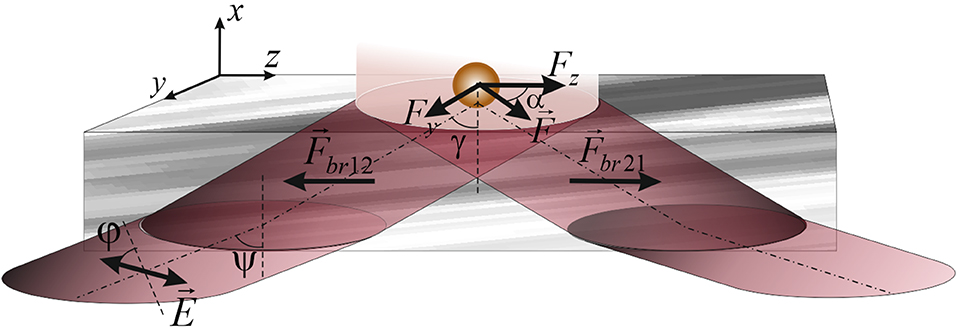
Figure 1. Scheme showing the propagation of a beam through the birefringent section of biotissue during the formation of vertical spin of an evanescent wave above the surface of the section. Here, φ, the azimuth of polarization of the probing beam;Ψ the angle of incidence of the probing beam, γ, the angle determining the propagation direction of the incident beam. , optical force directed to the external surface of the section and , optical force acting in the opposite direction. Fy, Fz, the components of the optical force determined by the action of the evanescent wave on the gold particles above the surface of the section, the resultant of which determines the direction of the particles motion (α).
The motion of gold particles above the birefringent biological slice is determined by the optical power generated by the evanescent wave.
Estimation of the rotational action of an elliptically polarized wave that propagates in a biological medium can be carried out as
is the time-averaged Maxwell stress tensor in SI-units determining the interrelation between the optical forces and the mechanical moment. Here ⊗ is the dyadic product, I is the unit matrix, is the surface-normal vector, is the magnetic inductance vector, and ε is the media permittivity. –is the electrical strength of the probing beam. Changing the angle of incidence ψ of the probing beam for different section thickness d, the polarization azimuth φ of this beam is selected, where the compensation of the optical torque (τbr12, τbr21) becomes possible.
Among the possible options for compensating the optical force in the volume of a biological section, we choose the optimal one, with respect to its experimental implementation. It can be shown that having the polarization azimuth of the incident wave at 45° at the ‘tissue-fluid' interface is realized when the incidence angle of a linearly polarized probing beam at the first surface of the section with the polarization azimuth of 79° is about 60° for the thickness of the section 100 μm. These parameters of the probing beam ensure complete internal reflection on the external surface of the section and the realization of an evanescent wave above the interface. This choice of parameters enables experimentally visualization of the transverse motion of gold particles in the surface layer of the tissue fluid, caused by an evanescent wave.
Consequently, the fixed motion [10] of gold particles over the surface of the biological section in the transverse direction can be explained by the action of the transverse spin component of the evanescent wave, which is generated under the above conditions.
Using expressions (1)–(4), the components of the optical force (Fy, Fz) of an evanescent wave were calculated.
The route of the nanoparticle motion in the evanescent wave is determined by the angle between the Poynting vector propagation along the z-axis and the resultant direction of the particle motion, which does not coincide with either the longitudinal (Fz) or the transverse (Fy) directions of the optical force components action.
As modeling results show, for the chosen incidence angle of 60°, the angle determining the direction of nanoparticles motion is about 11° as observed in the experiment.
In general, Brownian motion hampers the control of the nanoparticle motion in a homogeneous evanescent field. However, in this paper we are not interested in the process of capturing particles by the evanescent wave, but their displacement in this field, as demonstrated experimentally. Showing such a motion is rather a qualitative than a quantitative demonstration of the possibilities of using this phenomenon.
Figure 2 shows the experimental scheme.
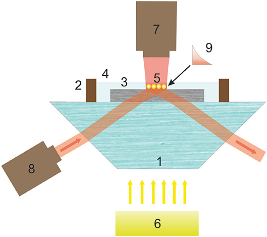
Figure 2. Scheme of experimental setup for demonstrating controlled motion of gold nanoparticles by an evanescent wave in the near-surface layer of a birefringent section. Here, 1, prism; 2, cuvettes with tissue fluid 4; 3, birefringent section; 5, gold nanoparticles controlled by evanescent wave 9; 6, white-light illuminating source; 7, laser beam provided particle trapping; 8, laser radiation source producing an evanescent wave.
As a radiation source the semiconductor laser 8 (980–4,000 mW Laser from Wavespectrum is used having the ability to control the beam power to 50–100 mW, which ensures the integrity of the biological tissue during irradiation. The laser was focused on the interface of the section—physiological medium 4 without spatial frequency filtration. The aperture of the beam was 6°.
The use of a prism to form a condition for TIR is an alternative to other approaches associated with the use of waveguides, fluorescence technology or microspheres [19–22]. The availability of this optical element determining the simplicity of achieving the necessary conditions for total internal reflection facilitates the evanescent wave creation. This establishes a significant advantage of the experimental realization of the transverse spin component.
In the suggested experiment, the focal spot was almost of square shape, with a diagonal of about 50 μm. The azimuth of the linear polarization of the test and incident beams was controlled by rotating the light source. The receiver of the radiation was a 1.3-megapixel CCD camera without a protective glass, sensitive in the infrared (IR) region. This enabled us to study both the particles, using the illumination in the visible region, and the position of the incident IR beam on the section. The radiation intensity was limited to work with biological objects.
To control the nanoparticles' motion it is necessary to avoid the particle interaction with the anisotropic mechanical environment nearby a solid interface [23]. An additional laser source 7 (660-nm laser) provides an optical trapping mechanism displacing the particles from the surface. This makes the particles remain in the area of the evanescent wave action (cf. Figure 2).
The results of the experiment are presented in the next picture (Figure 3). The flux of particles entrained by the evanescent wave moved in the transverse direction of the near-surface fluid layer, which is due to deviation from the original horizontal direction of motion.
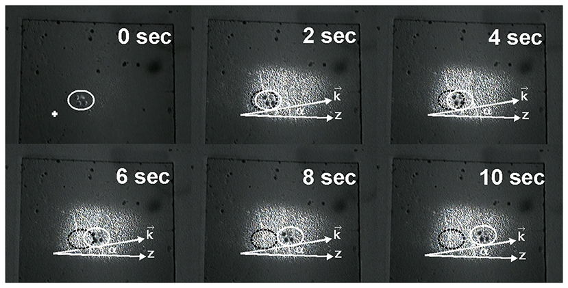
Figure 3. Photos demonstrating the change of gold nanoparticles about 60 nm size locations by the action of the evanescent wave, produced in the near-surface layer of the tissue: white ellipse notes the position of managed nanoparticles at different moments of time; black ellipse notes the initial position of these particles. α is the angle between directions z and (vector determining the direction of the resulting optical force action).
It was possible to approximate the average velocity of particle motion in our experiment to be in the vicinity of 35 . Angle α of particles deflection in the transverse direction under the action of the evanescent wave is about of 11°, which correlates with theoretical predicted results.
It is natural to assume that by changing the parameters of the probing beam, we are able to control the movement of nanoparticles in the super-surface layer of the biological object, thereby increasing the possibilities of transporting the correct amount of drugs to handle pathological biostructures.
RBS Manipulation by Evanescent Field
The next example, which demonstrates the evanescent field action on nanoobjects of organic origin, is the result obtained under the influence of the transverse spin component on shaped blood elements, in particular RBCs. In this case we form the evanescent field in which the action of the transverse component of the optical force becomes evident.
A distinctive feature of the results presented at this paper is the demonstration of the controlled motion of erythrocytes by an evanescent wave in a transverse direction that differs from the Poynting vector orientation that coincides with the direction of wave propagation.
The normal human erythrocyte has the shape of concavo-concave disc. The diameter of an erythrocyte is 7.82 ± 0.62 μm, and its minimal and maximal thickness at the center and at the limb are 0.81 ± 0.35 μm and 2.58 ± 0.27 μm, respectively. The mean magnitude of the cell volume of an erythrocyte is 94 ± 14 μm3, and the mean magnitude of the cell surface area is 135 ± 16 μm2. The mentioned sizes of an erythrocyte stem from photomicrographs [24]. The model of a concavo-concave disc corresponds well to native erythrocytes experimentally proven [25]. Considering an erythrocyte as a uniform disc with the mean erythrocyte volume, one can use the concept of single light-scattering by a cell where the cell organelles, and the cell membrane is believed to be thin enough to neglect their influence of its real thickness on the light scattering properties. The Mie theory of light scattering applied for such cases provides a comprehensive description of the energy transfer to the erythrocyte [25].
Observation of motion of isolated erythrocytes in whole blood is hampered by high concentration of cells. Concentration of erythrocytes is here diminished using an isotonic solution. However, the simplest use of physiological solution is not practical due to the lower viscosity of the solution changing the elasticity of erythrocytes. Consequently, we diminished the erythrocyte concentration using the natural medium of cells, viz. a blood plasma. Following this approach, both computer simulation and experimental demonstration of erythrocyte motion are carried out in blood plasma with refractive index (nsol = 1.37). To realize the total internal reflection, we use a flint prism with an index of refraction npr= 1.61, above which an erythrocyte with the refraction index ner = 1.407 is located [25] in the blood plasma. To avoid the temperature effects and irreversible temperature changes due to heating and destroying cells under illumination, one sets the power of radiation below 100 mW and the pulse repetition rate of about one μs.
By changing the angle of incidence of the beam at the prism, changes of the parameters of the evanescent wave, which propagates in the erythrocyte, are achieved. Thus, it is possible to set the maximum depth of penetration of the evanescent wave into the erythrocyte, which is about of 0.9 μm. The description of the mechanism of interaction of the evanescent wave with the erythrocyte suggests the use of the model [26], according to which the surface is divided into a set of facets of equal areas 0.01 μm2. The chosen size of the facets is necessary and sufficient for the description of the erythrocyte surface interacting with an evanescent wave. One computes the components of the optical force Fx, Fy, Fz and the magnitude of torque τ for each facet. In doing so, one takes into account the angle of incidence of radiation at the corresponding facet and the optical characteristics of the erythrocyte surface. Computer simulations were carried out for 3,340 facets interacting with an evanescent wave adding up the derived components of the optical force for three directions for each facet.
This model [24], makes it possible to define the spatial location of each of the facets, to determine the orientation of the plane of incidence of the evanescent wave on the facet. This enables description of the interaction of the wave with all obtained facets finding the part of the energy, which forms the component of the optical force for providing the motion of the erythrocyte.
Determination of the optical force (Figure 4) in the horizontal (YOZ)-plane with the components in the longitudinal and transversal directions (being typical for an evanescent wave) for the azimuth of polarization of the incident wave ±45° requires traditionally computation of the density of the spin and orbital angular momenta at the transversal (OY) and longitudinal (OZ) directions. The components are initially computed for each facet, followed by adding the corresponding components. The magnitudes of the components of the refracted evanescent wave at each facet are used for estimating the spin, orbital momentum density and the orbital angular momentum density in the longitudinal and transversal directions.
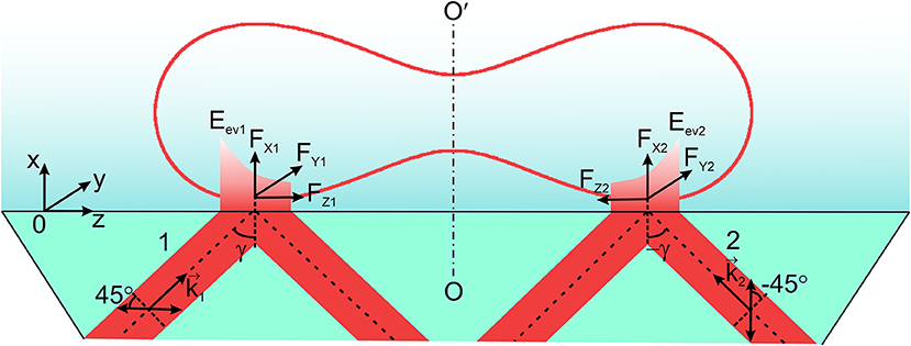
Figure 4. Two linearly polarized beams 1 and 2 with azimuths of polarization ± 45° with respect to the plane of incidence are incident on the prism at the angle (±γ). Here are the wavevectors of the incident beams; FX1, FX2, FY1, FY2, FZ1, FZ2 are the components of the optical force of the evanescent waves Eev1 and Eev2. OO′ is the axis of symmetry of an erythrocyte.
Following the expressions (1)–(3), taking into account the orientation of the i-th facet and the condition of illumination of the erythrocyte by the evanescent wave, the resulting momentum density at the i-th facet in the OZ—direction was determined.
and the transversal momentum caused by the vertical spin in the OY-direction
Here [t//]i, [t⊥]i are the refraction coefficients for the parallel and perpendicular components of an evanescent wave that impinges onto the i-th facet of an erythrocyte, is the angle between the normal to the facet at the point of incidence of the beam and the evanescent wave propagating along the OZ-direction, δi—is the orientation of the plane of incidence with respect to the vertical (XOZ)-plane.
In the framework of Mie light-scattering theory [2, 8] , where Δpi is the change of momentum density at the corresponding facet Si interacting with the evanescent wave for i = 1 to N, where N is the number of facets. We calculate the change of momentum density in y- and z-directions for the given i-th facet obtaining the quantities Δ[py]i and Δ[pz]i for the estimation of the components of the optical force [FY]i and [FZ]i.
The evanescent wave—being inhomogeneous in energy—is a source of gradient of the optical force in the OX direction, connected with the direction of propagation of the beam refracted at the i-th facet of the beam. The evanescent wave refracted at the i-th facet, in the OX direction, also determines another force component , where is the component of the time-averaged Maxwell's stress-vector, according to Equation (5).
The total component of the optical force in the OX-direction for the i-th facet is [FX]i = [Fx]i+[Fgradx]i. The next calculation step consists in recalculation of the found set of optical force components for each of the specified facets, [FX]i, [FY]i, [FZ]i, into the resulting components (FX, FY, FZ), by summation of the corresponding force components over all facets of the erythrocyte surface, , m = X, Y, Z.
A specially chosen scheme of two oppositely directed evanescent waves of the same amplitude and frequency forming above the prism provides the condition for transverse motion of the erythrocyte under the action of an evanescent field (Figure 4). In this model experiment, the longitudinal components of the optical force of the evanescent waves onto the erythrocyte are compensated leaving only the transversal components. Let us emphasize that the discussed effect only becomes possible if one uses two linearly polarized incident waves with the azimuths of polarization +45° and −45° with respect to the plane of incidence, so that two oppositely directed evanescent waves are of the same elliptical polarization.
For the symmetrical incidence of the beams with respect of the axis of symmetry OO′, the total longitudinal component of the optical force, FZ = FZ1 + FZ2, becomes equal zero. FZ1, Z2 are the longitudinal components of the evanescent waves excited by the linearly polarized incident waves with azimuths of polarization ±45°. The resulting rotational motion of a cell is compensated as well, and all this provides the condition for observation of a rectilinear motion of an erythrocyte in the transversal direction FY = FY1 + FY2, where FY1, Y2–are the transversal components of two evanescent waves.
The maximal magnitude of the resulting optical force occurs for an angle of incidence of 63°.
Transverse motion of an erythrocyte in blood plasma is caused by the action of the resulting force , where Fopt = FY is the optical force. At low Reynolds numbers, the damping factor or drag coefficient is found by approximating the disk shape of an erythrocyte by a sphere of the same cross-sectional area [25, 27], giving the Stokes force Fst = 3πηDv. Here η = 1.236 ×10⁻³Pa · s is the dynamic viscosity of blood plasma, D is the diameter of the corresponding cross sectional area of the cell, and v is the velocity of an erythrocyte. The equation of erythrocyte motion is , providing the estimation of the cell velocity. We emphasize that the RBC velocity will significantly depend on the angle of incidence of the beams.
In our experiment, specially prepared samples of blood plasma with isolated erythrocytes were used [8, 9].
The optical arrangement for experimental demonstration of erythrocyte motion in an evanescent field is shown in Figure 5. Semiconductor laser 1 with the wavelength λ = 980 nm was used in our experiment. We varied the radiation power from 5 to 500 mW. Moving erythrocytes are observed in white light from an LED display 9 using a micro-objective 10 (magnification 60x) and CCD-camera 12. Light filter 11 cuts off radiation from the IR laser.
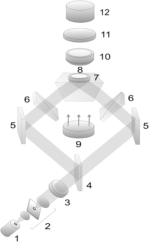
Figure 5. Optical arrangement for study of moving erythrocytes in an evanescent field: 1, laser; 2, beam expander with a spatial filter; 3, quarter-wave plate; 4, beam splitter; 5, mirrors; 6, polarizers; 7, total reflection prism; 8, cuvette with erythrocytes; 9, LED display; 10, micro-objective; 11, light filter; 12, CCD-camera.
The experimental results are shown in the following image (Figure 6). Over time, the position of the RBC changes in the transverse direction, due to the action of the transverse spin component of the evanescent wave.
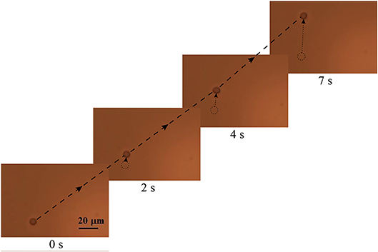
Figure 6. The change in the position of the RBC over time. Single arrows mark the movement of the erythrocyte in the transverse direction. A long dash-dotted line marks the trajectory of the erythrocyte.
The discrepancy of the results of computer simulation and the experimental study of the cell motion velocity does not exceed 30%.
Using of the proposed experimental setup and chosen theoretical approach allows us to obtain results demonstrating the controlled motion of the RBC under the action of the evanescent wave in the transversal direction, which can expand the prospects for the creation of a new generation of optical manipulators. Moreover, using of non-toxic materials for the body, carbon nanoparticles, based on the considered method, can successfully be applied for the needs of modern pharmacology and medicine.
Conclusions
This paper promotes results that illustrate the possibility for controlling of nano- and microobjects located in a biological environment by an evanescent wave. The transverse spin component of the evanescent wave generates a transverse component of the optical force, causing the motion of investigated objects in the transversal direction. At the same time, the rotational motion of nano-objects due to the circular polarization of the evanescent wave in the vertical and horizontal planes is realized. Such features of the evanescent wave arise at the TIR of a linearly polarized wave with the azimuth of polarization of 45° at the interface of the prism-biological medium. The consequence of such an influence of the evanescent wave is a complex pattern of motion of the studied objects—gold micro particles and red blood cells in a biological environment. The obtained experimental results are consistent with the results predicted theoretically.
Data Availability Statement
The datasets generated for this study are available on request to the corresponding author.
Author Contributions
OA: writing, theory. CZ: theory. JZ: experiment. SH: writing.
Conflict of Interest
The authors declare that the research was conducted in the absence of any commercial or financial relationships that could be construed as a potential conflict of interest.
References
1. Antognozzi M, Bermingham CR, Hoerber H, Dennis MR, Bekshaev AY, Harniman RL, et al. Direct measurements of the extraordinary optical momentum and transverse spin-dependent force using a nano-cantilever. Nat Phys. (2016) 12:731–5. doi: 10.1038/nphys3732
2. Bliokh KY, Bekshaev AY, Nori F. Extraordinary momentum and spin in evanescent waves. Nat Commun. (2014) 5:4300. doi: 10.1038/ncomms4300
3. Neugebauer M, Bauer T, Aiello A, Banzer P. Measuring the transverse spin density of light. Phys Rev Lett. (2015) 114:063901. doi: 10.1103/PhysRevLett.114.063901
4. Angelsky OV, Bekshaev AY, Maksimyak PP, Maksimyak AP, Mokhun II, Hanson SG, et al. Circular motion of particles suspended in a Gaussian beam with circular polarization validates the spin part of the internal energy flow. Opt Exp. (2012) 20:11351–6. doi: 10.1364/OE.20.011351
5. Angelsky OV, Bekshaev AY, Maksimyak PP, Maksimyak AP, Hanson SG, Zenkova C Y. Orbital rotation without orbital angular momentum: mechanical action of the spin part of the internal energy flow in light beams. Opt Exp. (2012) 20:3563–71. doi: 10.1364/OE.20.003563
6. Angelsky OV, Hanson SG, Maksimyak PP, Maksimyak AP, Zenkova CY, Polyanskii PV, et al. Influence of evanescent wave on birefringent microplates. Opt Exp. (2017) 25:2299–1. doi: 10.1364/OE.25.002299
7. Zenkova CY, Ivanskyi DI, Kiyashchuk TV. Optical torques and forces in birefringent microplate. Opt Appl. (2017) 47:483–3. doi: 10.5277/oa170313
8. Angelsky OV, Maksymyak PP, Zenkova CY, Maksymyak AP, Hanson SG, Ivanskyi DD. Peculiarities of control of erythrocytes moving in an evanescent field. J Biomed Opt. (2019) 24:055002–11. doi: 10.1117/1.JBO.24.5.055002
9. Angelsky OV, Zenkova CY, Maksymyak PP, Maksymyak AP, Ivanskyi DI, Tkachuk VM. Peculiarities of energy circulation in evanescent field. Application for Red Blood Cells. Opt Mem Neural Netw. (2019) 28:11–20. doi: 10.3103/S1060992X19010028
10. Angelsky OV, Zenkova CY, Ivanskyi DI. Mechanical action of the transverse spin momentum of an evanescent wave on gold nanoparticles in biological objects media. J Optoelectron Adv Mater. (2018) 20:217−23.
11. Ushenko AG, Ermolenko SB, Burkovets DN, Ushenko YA. Polarization microstructure of laser radiation scattered by optically active biotissues. Opt Spectrosc. (1999) 87:434–8. doi: 10.1117/12.370450
12. Zenkova CY, Gorsky MP, Ryabyi PA. The phase problem solving by the use of optical correlation algorithm for reconstructing phase skeleton of complex optical fields. Proc. SPIE. (2015) 9258:92582B. doi: 10.1117/12.2070415
13. Sabatini DM. Leading Edge Nanotechnology Research Developments. New York, NY: Nova Science Publishers (2007). 307 p.
14. Tuchin VV. The study of biological tissues by light scattering methods. Phys Uspekhi. (1997) 40:495–515. doi: 10.1070/PU1997v040n05ABEH000236
15. Zymnyakov DA, Simonenko GV, Tuchin VV. Dispersion dependence of optical anisotropy and degree of depolarization of fibrous tissues. Opt J. (2010) 77:69–74 (in Russian). doi: 10.1364/JOT.77.000577
16. Gryshchenko AY. Mechanooptics of Polymers. Sn. Petersburg, SP: SPSU edition (1996). 196 p. (in Russian).
17. Bashkatov AN, Genina EA, Kochubey VI, Tuchin VV. Estimation of wavelength dependence of refractive index of collagen fibers of scleral tissue. Proc SPIE. (2000) 4162:265–8. doi: 10.1117/12.405952
18. Zymnyakov DA, Sinichkin YP, Ushakova OV. Optical anisotropy of fibrous biological tissues: analysis of the impact of structural characteristics. Quant Electron. (2008) 37:777–83. doi: 10.1070/QE2007v037n08ABEH013611
19. Raichlin Y, Katzir A. Fiber-optic evanescent wave spectroscopy in the middle infrared. Appl Spectrosc. (2008) 62:55A−72. doi: 10.1366/000370208783575456
20. Soria S, Berneschi S, Brenci M, Cosi F, Conti GN, Pelli S, et al. Optical microspherical resonators for biomedical sensing. Sensors. (2011) 11:785–805. doi: 10.3390/s110100785
21. Skelton SE, Sergides M, Patel R, Karczewska E, Maragó OM, Jones PH. Evanescent wave optical trapping and transport of micro- and nanoparticles on tapered optical fibers. J Quant Spectrosc Radiat Transf. (2012) 113:2512–20. doi: 10.1016/j.jqsrt.2012.06.005
22. Hassanzadeh A, Nitsche M, Mittler S, Armstrong S, Dixon J, Langbein U. Waveguide evanescent field fluorescence microscopy: thin film fluorescence intensities and its application in cell biology. Appl Phys Lett. (2008) 92:233503. doi: 10.1063/1.2937840
23. Liu L, Kheifets S, Ginis V, Donato AD, Capasso F. Elliptical orbits of microspheres in an evanescent field. PNAS. (2017) 114:11087–91. doi: 10.1073/pnas.1714953114
24. Zhong MC, Wei XB, Zhou JH, Wang ZQ, Li YM. Trapping red blood cells in living animals using optical tweezers. Nat Commun. (2013) 4:1768. doi: 10.1038/ncomms2786
25. Tuchin VV. Optical Biomedical Diagnostics, Vol. 1. 2nd Revised ed. Bellingham, WA: SPIE Press (2017). 864 p.
26. Grover SC, Gauthier RC, Skirtach AG. Analysis of the behaviour of erythrocytes in an optical trapping system. Opt Exp. (2000) 7:533–9. doi: 10.1364/OE.7.000533
27. Fedele D, Fusi F. Energy for Health. Available online at: https://www.asalaser.com/sites/default/files/documenti/energy-for-ealth/e4h6_thermal_effects_nir_laser_radiation_10_15.pdf (accessed April 29, 2020).
Keywords: evanescent wave, vertical spin, bio-optic model, red blood cells, nano (micro) particle, biological tissue
Citation: Angelsky OV, Zenkova CY, Hanson SG and Zheng J (2020) Extraordinary Manifestation of Evanescent Wave in Biomedical Application. Front. Phys. 8:159. doi: 10.3389/fphy.2020.00159
Received: 20 January 2020; Accepted: 17 April 2020;
Published: 08 May 2020.
Edited by:
Olivier J. F. Martin, Federal Institute of Technology in Lausanne, SwitzerlandReviewed by:
Abdollah Hassanzadeh, University of Kurdistan, IranPradeep Kumar Gupta, Raja Ramanna Centre for Advanced Technology, India
Copyright © 2020 Angelsky, Zenkova, Hanson and Zheng. This is an open-access article distributed under the terms of the Creative Commons Attribution License (CC BY). The use, distribution or reproduction in other forums is permitted, provided the original author(s) and the copyright owner(s) are credited and that the original publication in this journal is cited, in accordance with accepted academic practice. No use, distribution or reproduction is permitted which does not comply with these terms.
*Correspondence: Oleg V. Angelsky, o.angelsky@chnu.edu.ua