Model-Free Position Control for Cardiac Ablation Catheter Steering Using Electromagnetic Position Tracking and Tension Feedback
 Junghwan Back
 Lukas Lindenroth
 Kawal Rhode
 Hongbin Liu
- 1Department of Informatics, King’s College London, London, United Kingdom
- 2Biomedical Engineering, King’s College London, London, United Kingdom
Cardiac ablation therapy is an effective minimally invasive treatment for cardiac arrhythmia. Catheter steering in the constrained environment during the procedure is considered difficult, particularly in providing accurate catheter tip positioning for ablating or for diagnosing the cardiac tissue. These difficulties and inaccuracies in the catheter tip positioning are a common reason for severe complications and a prolonged duration of the procedure. To improve the maneuverability and hence the accuracy of the catheter tip navigation, a model-free catheter tip position control with a new robotic catheter system is proposed in this article. A model-free tension control algorithm for steering the catheter has been developed and implemented in the robot. As seen in the experimental validation of the system, the model-free control is able to minimize position error up to 0.5 ± 0.2 mm from 80 mm position error within 7 ± 2 s. Furthermore, it shows the capability to react efficiently to external disturbances, such as external contacts or unwanted catheter shaft movement.
Introduction
Cardiac catheterization uses thin steerable tubes known as catheters for minimally invasive cardiac treatment (Biase et al., 2009). Through direct contact with intracardiac myocardial tissue, cardiac catheters are widely used for measuring cardiac electrophysiological function, and are also commonly employed for delivering ablation energy to the myocardium, as required for the treatment of cardiac arrhythmias (Natale, 2013). Steerable catheter tubes are inserted into the heart’s cambers through the femoral artery, allowing the targeted areas to be ablated (Hoffmann et al., 2010). These minimally invasive techniques provide significant advantages that include minimal incisions, quicker recovery time, less bleeding, and other economic benefits. However, the complex and delicate nature of those procedures make it difficult to steer the catheter manually, even for an experienced operator, which also causes prolonged operation times and complication by ablating ectopic location. Hence, extensive training is required for the clinician to perform such procedures, requiring development of task-specific manual dexterity and co-ordination (Halperin and Kolandaivelu, 2010). In addition, the procedures are mostly guided using X-ray images, thus the often long procedure times increase the radiation burden for both the clinician and patient. Frequently, the most time-consuming steps during the catheter ablation procedure are multisite diagnostic testing and ablation delivery. Therefore, fast and accurate catheter position control during the procedure is likely to reduce cardiac ablation procedure time significantly and to improve outcomes of the procedure.
A potential solution for these concerns is a robot assisted cardiac catheterization process. Over the past decade, various research platforms have been developed for this purpose, such as those described in Guo et al. (2007, 2010), Deng et al. (2013), Kesner and Howe (2014), and Rosa et al. (2015). Commercial robot catheter systems are also available, such as Sensei (Hansen Medical), Amigo (Catheter Robotics), and CorPath (Corindus Vascular Robotics). These commercially available robotic catheter systems provide teleoperative steering control and permit clinicians to be away from radiation during the procedure. However, the procedure time has not been demonstrated to be notably reduced (Kanagaratnam et al., 2008).
A number of methods have been studied to achieve precise and effective positioning of the catheter tip. The pseudorigid body 3R model was developed to control the position of conventional catheter tips in Khoshnam and Patel (2013). Jacobian-based position control has been derived in Penning et al. (2012). An actuated catheter system with 3D ultrasound image guidance to compensate for fast motion of cardiac tissue was proposed in Kesner and Howe (2011). In the latter, the catheter steering mechanism was optimized for single planar deflection, and twisting of the conventional catheter tip. The theoretical curve model based on the constant curvature assumption was reported for four-way tendon driven catheter position control (Camarillo et al., 2008). In Vasilyev et al. (2015), a new device to remove target tissue in the heart has been reported. The device was attached at end of the concentric tube manipulator and was positioned using a forward kinematic model. A miniature mobile robot has been developed for exploring the inner surface of the beating heart using a vacuum line in the robot (Patronik et al., 2009). This robot demonstrated accurate positioning with an error of about 0.7 mm, but the surface following to reach a target could only be achieved with slow navigation.
Recent studies have been conducted without considering catheter translation, using a rigid catheter shaft or excluding external contact (Kesner and Howe, 2011; Penning et al., 2012; Khoshnam and Patel, 2013). Cardiac catheters comprise of a flexible shaft for safer insertion of the catheter into the heart’s chamber through the complex vasculature. The shaft, however, is stiffer than catheter tip for independent deflection of the catheter tip under increasing tension. We observed that the catheter shaft also deflects under loading, as shown in Figure 1A. The catheter shaft deflection can be an error source in catheter kinematic models. Additionally, the internal tendon friction and hysteresis of the flexible material must be considered (Eppinger and Seering, 1987; Chiaverini et al., 1999) to provide accurate kinematics for position control. Furthermore, external contacts along catheter body by contacts in the vasculature should also be considered as external forces in the kinematics model as shown in Figure 1B. Considering the dynamic muscle contractions in the heart and the blood flow acting on the catheter, the performance of a model-based control could lose accuracy and efficiency (Kesner and Howe, 2011; Samuel and Robert, 2011). Predictive algorithms for beating heart motion have been reported in Bachta et al. (2009) and Tuna et al. (2013). These predictions, however, were evaluated under a regulated heart rhythm and at frequencies slower than real-time. Arrhythmic heart rhythm could therefore make difficult to predict heart motion. An alternative way to compensate for the heart beat is by compensation in the robotic catheter control. Accounting for these above mentioned physical phenomena can result in a high level of complexity in a model-based control approach. To address the previously mentioned model limitations Eppinger and Seering (1987), Chiaverini et al. (1999), Camarillo et al. (2008), Patronik et al. (2009), Kesner and Howe (2011), Samuel and Robert (2011), and Vasilyev et al. (2015), we develop a model-free catheter tip position control. The model-free controller is implemented on a new robotic catheter steering system for autonomous catheter position control. To increase controllability and dexterity, a four-way tendon driven catheter tip as proposed in Ataollahi et al. (2013) is utilized. To reduce the backlash associated with rotary motors, each tendon is driven by a linear actuator. Four tension sensors using cantilever beam structures and strain gages are designed and calibrated to provide tension feedback. Each tendon is tied to an individual tension sensor, which is fixed on the linear actuator. Two magnetic trackers (NDI Aurora® EM) are inserted into base and end point of the catheter tip to provide catheter position feedback. The catheter position is adjusted iteratively based on the position and tension feedback to reach the desired target location. Therefore, the contributions of this study are the evaluation of the model-free catheter position control which is capable of compensating the position error from the shaft deflection as well as the external contact induced by heart contraction and collision.
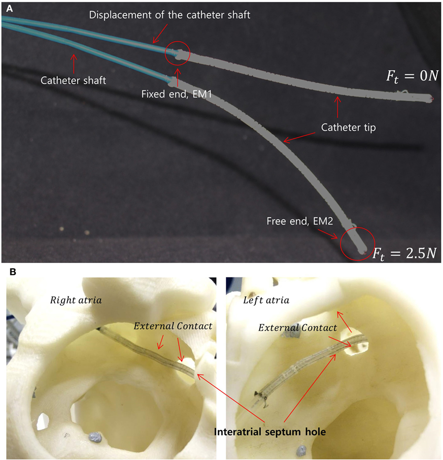
Figure 1. (A) Two different catheter shapes under different tension magnitudes indicating the catheter shaft displacement under the increasing load. The locations of the electromagnetic (EM) trackers in the catheter tip are shown as EM1 and EM2. (B) Example scenario of external loads on the catheter tip due to interatrial hole contact (also known as the trans-septal puncture) and heart chamber wall.
During the evaluation of the model-free control, the catheter tip was able to reach a location with 0.5 ± 0.2 mm error in five repeated trials. Additionally, the model-free control was compared to an inverse Jacobian method using the constant curvature assumption. The results showed that the model-free approach was 1.5 times faster following a straight line than the inverse Jacobian method based on constant curvature model in the free space experiment. When the shaft was constrained by an external contact, the inverse Jacobian method showed comparable results such as 0.5 ± 0.2 mm and about 10 s to minimize the position error. Furthermore, the catheter tip was capable of following the target circles (∅ 48 mm, ∅ 24 mm, and ∅ 14 mm) with a selected 3 mm error margin and a catheter tip velocity of 5 mm/s.
Overview of the Linearly Actuated Catheter Robot System
The tension sensing and tension control implemented in this study were adopted from our previous work presented in Back et al. (2015). The entire robotic catheter system is shown in Figure 2.
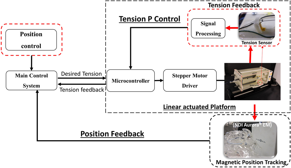
Figure 2. Schematic diagram showing the configuration of the linear actuated catheter robot.
The robotic catheter system comprises of a linearly actuated tendon-driven robot platform, a steerable four-way tendon-driven catheter tip which has been introduced in Back et al. (2015), as well as catheter position tracking and tension sensors to satisfy the requirements of the catheter position control based on tension adjustment.
In order to provide position feedback to the catheter control, the catheter tip in Ataollahi et al. (2013) has been modified for inserting electromagnetic (EM) tracker at the catheter tip free end and fixed end as shown in Figure 1A. Employing the four-tendon catheter allows to achieve a 3D works space without requiring the twist of the catheter (Ataollahi et al., 2013).
Inherent mechanical characteristic of the helix structure in the segment provided for good repeatability, low hysteresis, high maneuverability and flexibility for safety. The catheter was made with 12 segments and the total length of the catheter tip was 117 mm. A polyethylene fishing line (G = 1.04 × 10⁵N/mm2) was inserted into the catheter to be used as the tendons as shown in Figure 3. We observed that the catheter obtained the maximum bending when 5 N is applied to a tendon. The tendon extension is negligible under this level of load.
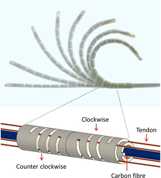
Figure 3. Bending motions of the catheter tip and helical segment structure with alternating clockwise and counter-clockwise helix orientations.
The linearly actuated tendon driven robot platform comprises of five linear guides to avoid backlash, slack, and tangled tendons. The five linear actuators are controlled by the catheter control algorithm via a microcontroller (Arduino Mega). The tension sensors are developed using strain gages and special cantilever beam structure for tension feedback (Back et al., 2015). The tension sensor communicates with the main Linux computer via a microcontroller. For safer catheter control, over tension on the tendons and mechanical slack are both prevented by achieving desired tension values. During the catheter position control, the desired tension value is achieved using a P controller. The catheter is navigated using the added magnetic trackers, and its tip is represented on a 3D reconstructed surface rendering of a phantom heart in the ROS visualization virtual environment. The system proposed in this work allows for improved manageability of the catheter tip, safer catheter controlling with real-time tension sensing.
Tension Sensing
A cantilever beam structure-based tension sensor is created to investigate interplay between the tension driven actuation and the catheter tip whilst the catheter is controlled (Back et al., 2015). Detecting the loosening tension on the tendons enables the controller to prevent slack and backlash.
A strain gage is attached to the surface of the cantilever beam structured sensor body as shown in Figure 2. The bending of the cantilever beam structure changes resistance value of the strain gage, thus the output voltage value is changed depending on the magnitude of the applied tension. The four tension sensors are examined to observe hysteresis and repeatability as shown in Figure 4. The resolution, the average accuracy, and the hysteresis of the tension sensor are determined as 0.03 N, 97.5%, and 6%, respectively. The tension sensing can therefore be considered reliable enough for the use in the tension-based control system.
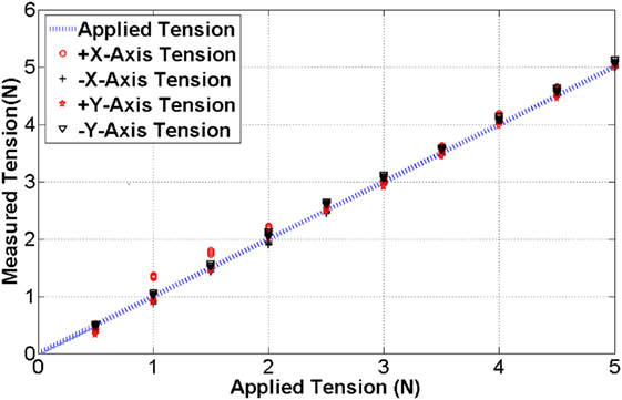
Figure 4. The blue line indicates the benchmark tension while the black and red dots are measured tension during the calibration.
Tension Control
Tension feedback control in the model-free control is an essential requirement to continuously maintain the desired tension value. Another requirement in the tension control is the avoidance of tension overshoot which introduces unwanted contact or general position overshoot during catheter steering. Consequently, the aim of the tension control is maintaining tension accurately with a fast rise time. Standard PID controller provides a sophisticated solution for feedback control. However, the deflection of the sensor structure is less than 0.3 mm and therefore requires high resolution and highly responsive linear actuation with highly responsive PID controller. To reduce the demands to such a controller, the linear travel distance is extended using a spring. A spring is tied up to the tension sensor as shown in Figure 5.
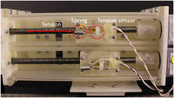
Figure 5. Integrated linear actuator with tension sensor and spring.
The use of the spring shows an increase of the travel distance from 0.3 mm to 4 cm under maximum tension (5 N). Therefore, the spring introduces a suspension effect to the tension feedback control eliminating the need for a highly responsive PID controller. In the following, a P controller is utilized to control the tendon tensions. The P gain value is determined experimentally and set to 120 in this study. To evaluate the tension control, step tensions from 1 to 5 N in 1 N increments are given as desired targets and the tension control with spring and without spring are compared. The target tension is held over a period of 25 s. The system responses are shown in Figure 6.
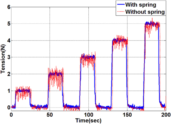
Figure 6. Tension control results by applying target tensions between 1 and 5 N. The resulting tension in the evaluation with a spring is indicated by the blue line and the tension result without a spring is shown as the red line.
As indicated by the results shown in Figure 6, the setup with the added spring shows a significantly lower steady state error. Vibration of the catheter tip position has been observed during the tension control without the spring but was eliminated by the spring effect. The tension is maintained accurately following the given target tension with ±0.03 N tolerance error. The settling speed is 0.5 s/N. It is therefore concluded that the proportional tension controller with the travel distance extension using the spring is sufficient for the given application with a suitable setting time, negligible tension error and minimal overshoot during the control.
Model-Free Tension Control for Catheter Steering
Position control of catheters using inverse kinematic models, such as the pseudorigid body 3R model or constant curvature based Jacobian methods have been studied by a number of research groups (Kesner and Howe, 2011; Penning et al., 2012; Khoshnam and Patel, 2013). Moreover, kinematic control of a continuum manipulator using EM tracker and fuzzy control has been proposed in Qi et al. (2016). Proposed solutions rely on the assumption that the catheter is fixed on a rigid frame and operated in free space with the contact force applied on the catheter tip. However, we observed experimentally that there are sources of errors during catheter position control inside a constrained space such as the heart’s chambers. Developing an accurate analytical kinematics model is therefore difficult. First, due to the compliance of the catheter shaft as well as the surrounding arteries, when the tension is applied to the catheter tip, both the catheter tip and the shaft may bend as illustrated in Figure 1A. Since the mechanical properties of the environment are often not known, the shaft deflection cannot be predicted analytically. Moreover, when the catheter tip is steered inside a tightly constrained workspace, an unpredicted contact could happen at any part of the catheter tip, as show in Figure 1B. In this case, an inverse kinematic model based on the assumption of single contact at the tip end becomes invalid. Therefore, we propose a simple yet robust tension based catheter position control method based on a PID control method for iteratively compensating position errors. A schematic description of the catheter tip bending is shown in Figure 7A. As shown in Figure 7A, there are four tendons inside the catheter; one pair of tendons generates bending about the x-axis, the other pair generates bending about the y-axis.
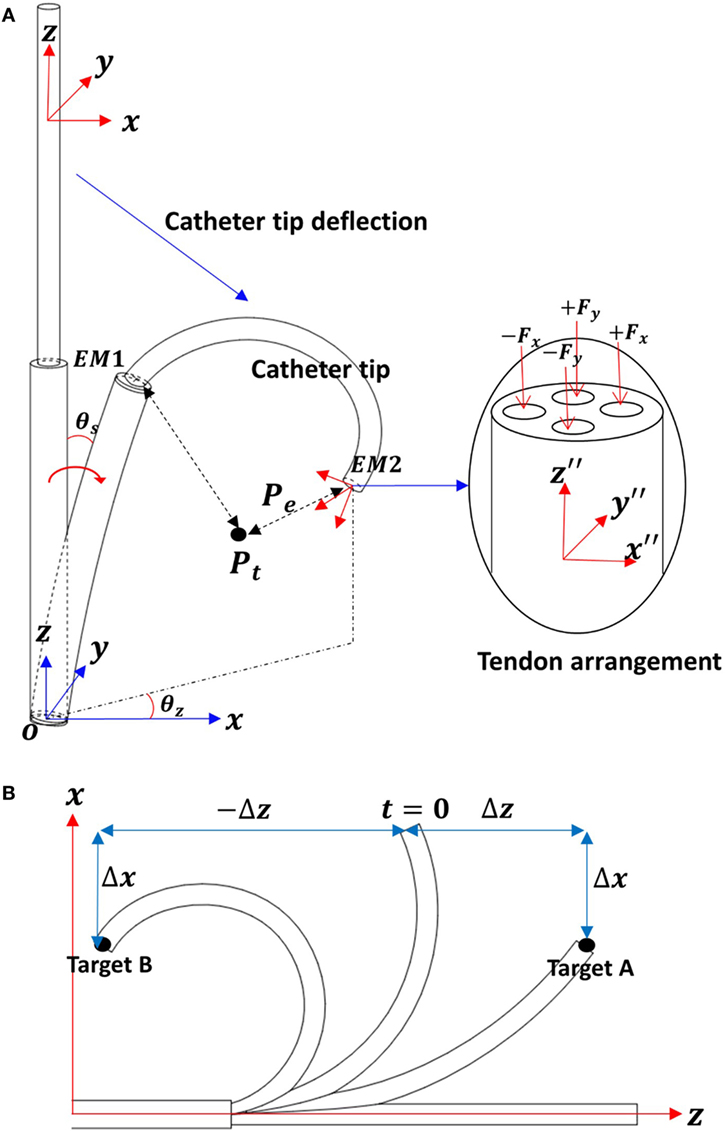
Figure 7. (A) Schematic descriptions for the catheter tip deflection. (B) Two-dimensional work space to describe the multiple solutions on x-axis.
Two EM trackers are integrated into the catheter tip; EM1 is in the fixed end and EM2 in the free end of the catheter tip. The two EM tracker positions are tracked with respect to the global frame O. The catheter tip position (Ptip) is calculated with respect to the fixed end (EM1) as Eq. 1. The target position Pt with in the global frame O is represented with respect to EM2 as shown in Eq. 2
The position error is
In consideration of the catheter tip workspace, there are two z values associated with a given x, y position. For example, as shown in Figure 7B, when the catheter tip has a configuration at t = 0, the errors on x-axis Δx for target A and B are equal. If the applied tension cannot be determined by x-axis position error Δx, then the z-axis displacement is taken into consideration.
In this catheter control, the applied tension values in both x- and y-axes are given in Eqs 4 and 5.
In this catheter control, the applied tension values in both x- and y-axes are given in Eqs 4 and 5. Let , the tension adjustment value ΔFt, the position error is and the translation velocity ΔT be calculated as
The Z-axis error is compensated by the translational motion, until the desired catheter tip position is achieved. In this work, the translation direction is also determined by sign(Δz).
PID gains have to be defined properly to reduce overshoot and increase the speed of convergence. In this catheter position control experiment, the gain values are determined experimentally as 0.02, 0.01, and 0.001, respectively. PID gains for the translation have a different value to adjust velocity. In this study, the PID gain values for the translation are 120, 35, and 10, respectively. The desired tension values to control catheter position are updated using the calculated ΔFt in Eq. 7.
The control diagram is shown in Figure 8.
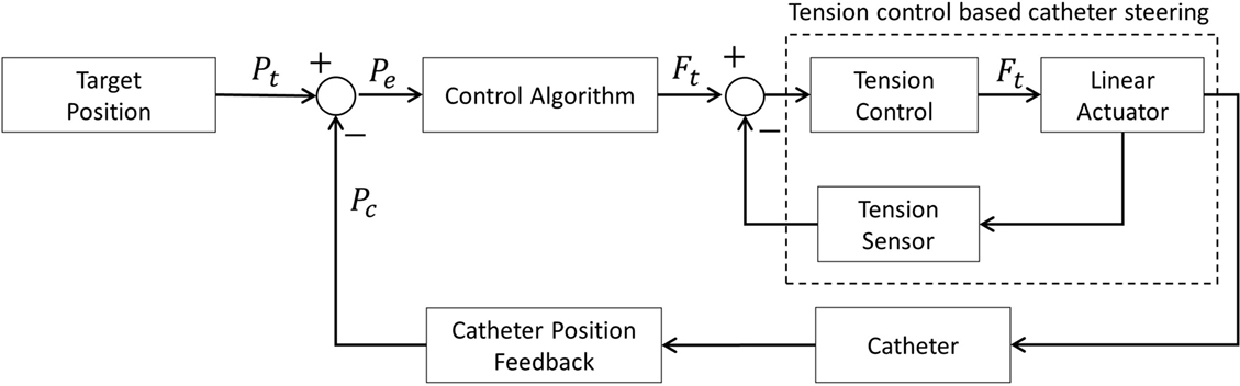
Figure 8. Tension based position control diagram.
Since the shaft is able to deflect when tension is applied to any tendon, cross talk occurs between the x-axis and y-axis bending. For example, tension applied to the x-axis tendon will generate y-axis deflection when the θz is non-zero (see Figure 7B). However, considering the significantly higher stiffness of the shaft compared to the catheter tip, we can assume that the dominating bending is along the desired bending axis. Hence, although there is a small error in the prediction at each step, the catheter eventually reaches the desired goal after several iterations of error compensation.
The control method is implemented in the Robot Operating System, and the frequency of the calculation is fixed at 40 Hz. The tension and the position control algorithm are executed in parallel, thus the desired tension value and translation direction are updated continuously. This allows to reduce the number of iteration and suppress overshoot during the control.
Control Evaluation
Performance of the Model-Free Position Control
Three PID, PD, and P controllers are tested with a zero error margin, so that the distance errors, when each controller is used, could be measured. The catheter is placed at an initial location and moved to the target location as shown in Figure 9A. The distance error with respect to the execution time during the movement from one target to another is shown below.
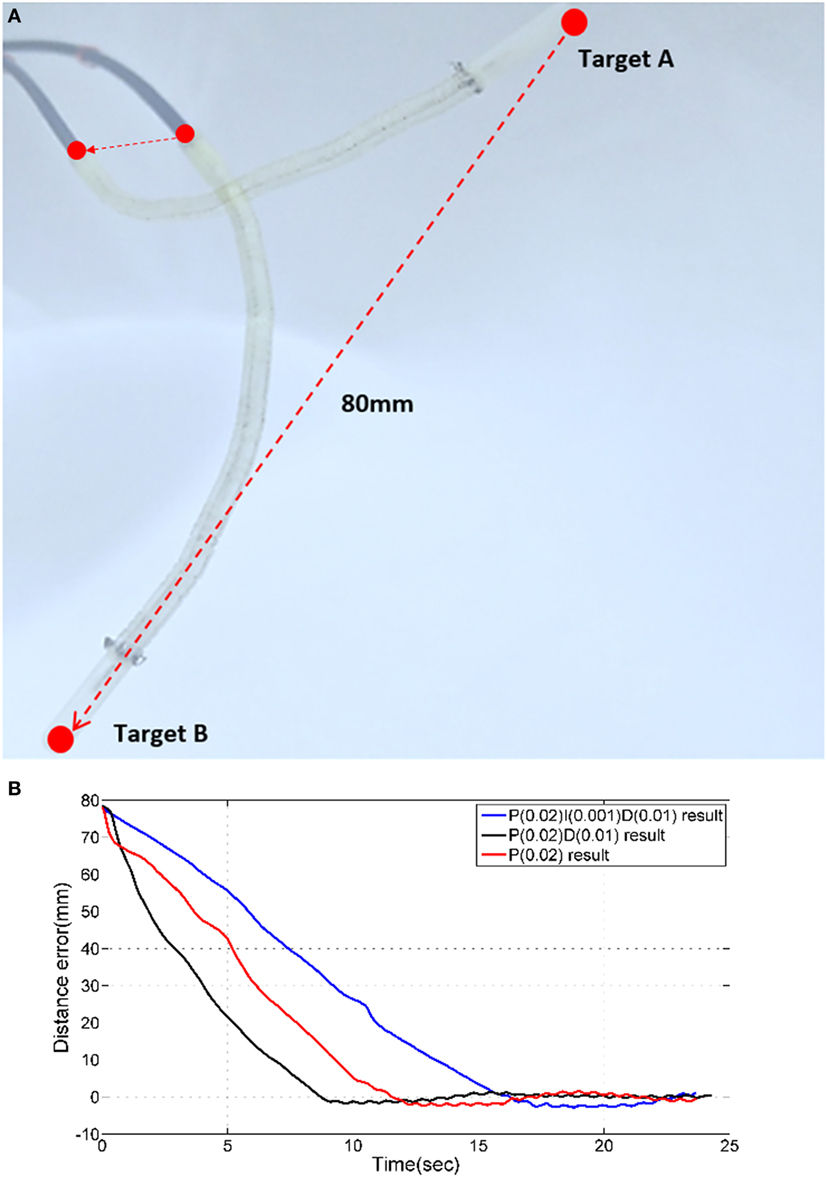
Figure 9. (A) Two targets for PID time response experiments. (B) Time responses of PID, PD, and P controllers.
The magnetic tracker comprises a position accuracy of approximately ±0.5 mm. Therefore, we consider the target is reached when the absolute error is less 0.5 mm. As shown in Figure 9B, PID, PD, and P position control results do not have a considerable overshoot error. For each of the three control approaches, a different time response is observed. The PD controller reduces the distance error from 80 to 1 mm the fastest with approximately 7 s. All controllers require approximately 1.2 s to reduce the distance errors from 5 to 1 mm. It can be observed that when the error is reduced from 1 to 0.5 mm, the PD controller outperforms the others (PID = 17 s, PD = 8 s, P = 12 s).
Comparative Study
The model-free control is proposed to control the catheter tip position in constrained environments, but the performance of the model-free position control compared to a model based position control is still to be evaluated. Thus, the model-free position controller was compared to an inverse Jacobian method for the catheter tip position control. The Jacobian matrix was calculated using a constant curvature model as shown in Figure 10.
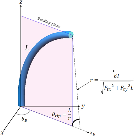
Figure 10. Catheter tip position calculation in the bending plane using the constant curvature assumption.
E, I, and L are Young’s modulus, second moment of inertia and catheter tip length, E is 5.1 × 10⁶ N/m2 as defined in Back et al. (2016), I is calculated as 3.97 × 10⁻¹² m4, and L is 117 mm. The catheter tip position in the bending plane is represented in 3D using rotation of θB. The equation to calculate θB using tension is
The equation to calculate position of the catheter tip can be defined as
where xB is x-axis position of the catheter tip in the bending plane as shown in Figure 10, and T is value of the translation. These equations were presented in Kesner and Howe (2011) and Qi et al. (2016). Tension values (Ftx and Fty) in combination with the equations in the Figure 10 are used to calculate the Jacobian matrix in this article as Eq. 10.
During the position control, the Jacobian matrix is updated using the measured tension. Required tension values are calculated by multiplying the inverse Jacobian matrix with the measured position error as shown in Figure 11. Therefore, the Jacobian based position control compensates the position error iteratively based on the constant curvature model. Note that the PID gain in the tension controller is optimized for reducing position error effectively.
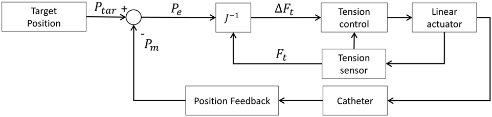
Figure 11. Inverse Jacobian method for catheter tip position control—schematic diagram.
The model-free control and the inverse Jacobian control are compared in three experiments; the first experiment comprises of a single target in free space, in the second experiment the catheter tips follows a line and in the last experiment a single target is approached with an external contact as shown in Figures 12–14. In these experiments, the same initial position and target position are given to the both position controls.
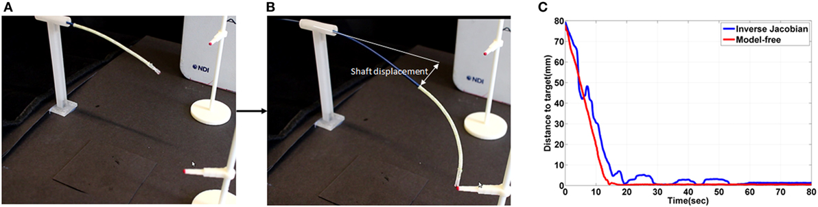
Figure 12. (A) initial shape of the catheter in the free space experiment (B) shape of the catheter after contact on the target location using the free model position control and showing the shaft deflection during the experiment (C) the absolute distance error during the experiment.
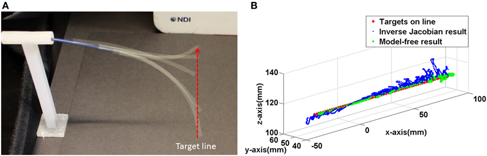
Figure 13. (A) The captured catheter shape during following the target line (B) trajectories of the both controller during following the target line.
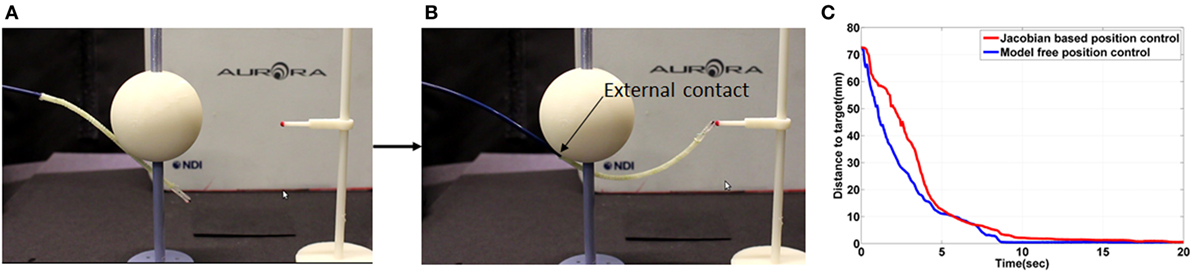
Figure 14. (A) Initial shape of the catheter in the external contact experiment (B) shape of the catheter after contact on the target location using the free model position control (C) the absolute distance error during the external contact experiment.
Both position control approaches were able to reduce the position error down to 0.5 ± 0.2 mm. The gradient of the reducing position error in both are similar as shown in Figure 12C between 0 and 10 s. In the model-free position control, the position error was reduced until 0.5 mm at 15 ± 3 s. However, a 2.7 s longer time to reduce to the steady state was observed in the inverse Jacobian control as shown between 20 and 80 s in Figure 12C.
In the inverse Jacobian control case, the two tensions (Ftx, Fty) are coupled by the bending angle θB. The shaft deflection causes errors in θB and θtip which introduces errors to the Jacobian matrix calculation, resulting in flawed tension adjustments. Thus, the inverse Jacobian method takes time to reduce the steady-state error further, as seen in the overshoot during the control. In the model-free control, the position errors are compensated individually. For example, the x-axis position error is compensated only by the x-axis tension Ftx. Also, the model-free control adjusts the tension by position error gradually and individually. Consequently, the individual position error compensation in the model-free control steadily guides the catheter tip position on the target with less time to reduce the steady-state error. This steady-state error problem is clearly demonstrated in the line following experiment shown in Figure 13.
In the line following experiment, 67 targets were defined on a 134 mm long, straight line. The distance between the targets was 2 and 1 mm error margin was given to the both controller. As the result in the single control experiment the inverse Jacobian control had larger fluctuation around the target line. On the other hand, the model-free control showed a trajectory close to the line as shown in Figure 13B. Furthermore, the larger movement around the target during the inverse Jacobian control resulted 1.5 times (135 s) slower than the model-free control (90 s). Moreover, the RMSE of the inverse Jacobian was higher; 3.4 ± 2.1 mm from the inverse Jacobian control and 1.5 ± 1.1 mm from the model-free control.
Both position controllers were evaluated with an external contact on the catheter. As shown in the result in Figure 14C, both position controls showed similar time to minimize error. The external contact constrained the shaft deflection so that the Jacobian matrix was calculated more accurately. The time to reduce steady state error was significantly reduced in the inverse Jacobian control. If the catheter shaft is not moved, the model-free position control has similar performance as the inverse Jacobian method. However, the flexible fixed frame by the catheter shaft is, the inverse Jacobian method requires further optimizations such as actuator velocity gain, material property and consideration of the shaft deflection in the model. Therefore, the model-free control is more suitable for the catheter tip position control with the flexible catheter shaft, and it is also more convenient to optimize the given controller.
Following Multiple Targets
Additional control evaluation experiments are conducted by controlling the catheter to reach points along a circular path, since manual steering along a circular trajectory is considered difficult for the operating clinician. An experimental setup is designed to evaluate the robotic platform along three circular paths in free space, as shown in Figure 15A. Sixteen targets are given on each circular path. The diameters of the circles are chosen to be 50, 30, and 15 mm, where 15–50 mm are representative distances traversed inside the heart during ablation. In this scenario, the previously derived PD controller is used. The catheter tip follows each circular three times continuously with a given error margin of 2 mm. This margin determines the distance at which a target point is deemed as being reached. The trajectories of the experiment are represented with respect to the circle plane as shown in the Figure 15.
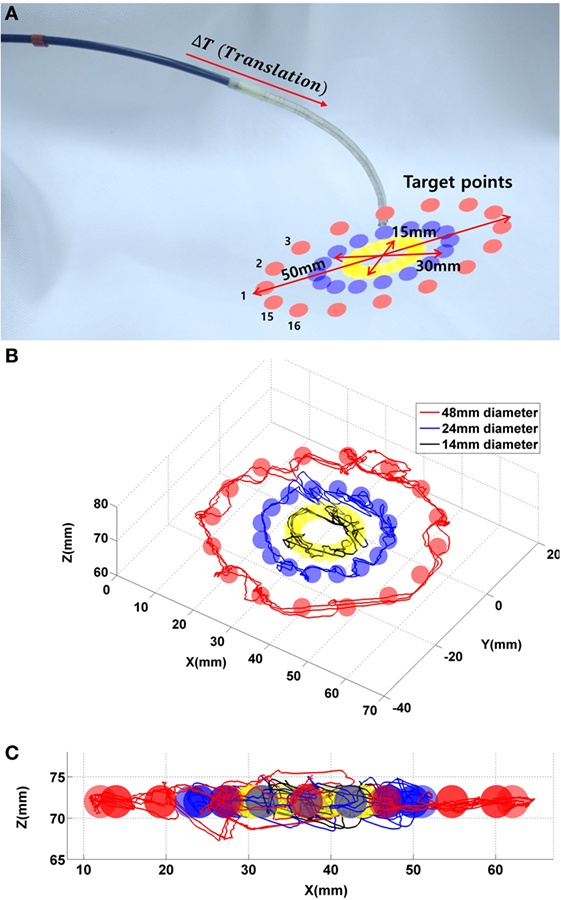
Figure 15. (A) 48 targets in the three circles. (B) Catheter tip trajectories on the circle plane during the control evaluation experiment with three target circles. (C) Catheter tip trajectories on x–y plane.
The catheter reaches 144 target points to follow all circular paths three times, with a maximum overshoot in x-, y-, and z-axes of 7, 4.5, and 5.1 mm, respectively. In addition, the recorded trajectory of the catheter is compared to the given circular line with a RMSE of 4.6 ± 2.1 mm. The RMSE is shown with a given error margin of 3 mm. In the control evaluation experiments, the target points on the circular paths are at a fixed distance from one another. For the circular path with 50 mm in diameter, the robot requires approximately 2 min to finish the entire path; for the circular path with 30 mm in diameter, the robot requires 1.4 min; for the 15 mm diameter, the robot requires 0.5 min to complete an entire circle.
Future Work and Conclusion
In this work, a model-free catheter position control is demonstrated with a robotic catheter system which comprised of a linearly actuated tendon driven robotic platform with tension sensing. In the Section “Performance of the Model-Free Position Control,” different PID controllers were implemented as part of the model-free position control approach. The PD control of the model-free position control showed faster than the P and PID controller. The catheter tip reached the target location with a 0.5 mm position error. The model-free position control was compared to the inverse Jacobian method using a constant curvature model. Both investigated position controllers were able to reduce position error down to 0.5 ± 0.2 mm. The shaft deflection, however, caused errors in the calculation of the Jacobian matrix which caused overshoot of the catheter tip position. Thus, the inverse Jacobian method took 2.7 times longer to achieve target location within 0.5 ± 0.2 mm position error. In the external contact experiment, both controllers showed comparable results with the constrained the catheter shaft. The model-free catheter tip position followed 144 contact locations which were spread along the different circles. The catheter tip could reach each target within given error margin, which was 3 mm in this study. Therefore, the model-free position control is applicable to navigate the catheter tip to a target location under external disturbances such as an external contact and shaft deflection. Furthermore, the iterative error minimization of the model-free control approach makes it applicable to constrained workspaces.
However, during the catheter steering in the constrained environment inside the heart chamber the tip could get stuck in a local distance minimum toward the goal, which could be an environment contact. In this case, path planning is required to escape from the constraint. Therefore, in future research, this model-free control will be enhanced with a path planning algorithm to avoid the catheter tip getting blocked by environmental contacts and to improve efficiency of the catheter navigation by determining an efficient path. This model-free position control with additional path planning will then be compared to a surgeon’s manual catheter steering capabilities to define how the autonomous catheter navigation could potentially improve catheter steering accuracy and time. In additional future work, we aim to estimate the contact force based on the catheter position tracking by extending our previous work in Back et al. (2016). The model-free position control will be modified to control contact force using the force feedback from the estimation. Therefore, the future autonomous catheter steering platform could be able to deliver RF energy at the desired target location autonomously without any physical contact force sensor.
Author Contributions
JB developed on the system design, controller implementation and experimental validation of the automated catheter system. LL contributed to the experimental evaluation described in the work. KR gave important directives in assessing the medical background and performance of the catheter system, and HL supervised the project and stating the problems and outline of the work.
Conflict of Interest Statement
The authors declare that the research was conducted in the absence of any commercial or financial relationships that could be construed as a potential conflict of interest.
Supplementary Material
The Supplementary Material for this article can be found online at https://www.frontiersin.org/article/10.3389/frobt.2017.00017/full#supplementary-material.
Video S1. Model-free catheter position control is compared to the inverse Jacobian position control based on the constant curvature model. The result is analyzed in comparative study section.
References
Ataollahi, A., Karim, R., Soleiman Fallah, A., Rhode, K., Razavi, R., Seneviratne, L., et al. (2016). 3-DOF MR-compatible multi-segment cardiac catheter steering mechanism. IEEE Trans. Biomed. Eng. 63, 2425–2435. doi:10.1109/TBME.2013.2276739
Bachta, W., Renaud, P., Cuvillon, L., Laroche, E., Forgione, A., and Gangloff, J. (2009). Motion prediction for computer-assisted beating heart surgery. IEEE Trans. Biomed. Eng. 56, 2551–2563. doi:10.1109/TBME.2009.2026054
Back, J., Karim, R., Noh, Y., Rohde, K., Althoefer, K., and Liu, H. (2015). “Tension sensing for linear actuated catheter robot,” in International Conference of Intelligent Robotics and Application (Portsmouth, UK), Vol. 9245, 472–482.
Back, J., Lindenroth, L., Karim, R., Althoefer, K., Rhode, K., and Liu, H. (2016). “New kinematic multi-section model for catheter contact force estimation and steering,” in IEEE/RSJ International Conference on Intelligent Robots and Systems (Daejeon, South Korea) 2122–2127.
Biase, L. D., Natale, A., Barrett, C., Elayi, C. S., and Chingm, C. K. (2009). Relationship between catheter forces, lesion characteristics, “popping,” and char formation: experience with robotic navigation system. J. Cardiovasc. Electrophysiol. 20, 436–440. doi:10.1111/j.1540-8167.2008.01355.x
Camarillo, D. B., Milne, C. F., Carlson, C. R., Zinn, M. R., and Kenneth Salisbury, J. (2008). Mechanics modeling of tendon-driven continuum manipulators. IEEE Trans. Robot. 24, 1262–1273. doi:10.1109/TRO.2008.2002311
Chiaverini, S., Siciliano, B., and Villani, L. (1999). A survey of robot interaction control schemes with experimental comparison. IEEE Trans. Mechatronics 4, 273. doi:10.1109/3516.789685
Deng, T., Wang, H., Chen, W., Wang, X., and Pfeifer, R. (2013). “Development of a new cable-driven soft robot for cardiac ablation,” in IEEE International Conference on Robotics and Biomimetics (Shenzhen, China), 728–733.
Eppinger, S. D., and Seering, W. P. (1987). “Introduction to dynamic models for robot force control,” in IEEE Control Sys Magazine, 48.
Guo, J., Guo, S., Xiao, N., and Tamiya, T. (2010). “Danger avoiding method based-a novel catheter operating system,” in IEEE International Conference on Mechatronics and Automation (Wuhan, China), 1569–1574.
Guo, S., Kondon, H., Wang, J., Guo, J., and Tamiya, T. (2007). “A new catheter operating system for medical applications,” in IEEE/ICME International Conference on Complex Medical Engineering (Beijing, China), 82–86.
Halperin, H. R., and Kolandaivelu, A. (2010). MRI-guided electrophysiology intervention. Rambam Maimonides Med. J. 1, 1–18. doi:10.5041/RMMJ.10015
Hoffmann, B. A., Koops, A., Rostock, T., Mullerleile, K., Steven, D., Karst, R., et al. (2010). Interactive real-time mapping and catheter ablation of the cavotricuspid isthmus guided by magnetic resonance imaging in a porcine model. Eur. Heart J. 31, 450–456. doi:10.1093/eurheartj/ehp460
Kanagaratnam, P., Koa-Wing, M., Wallace, D. T., Goldenberg, A. S., Peters, N. S., and Wyn Davies, D. (2008). Experience of robotic catheter ablation in humans using a novel remotely steerable catheter sheath. J. Interv. Card. Electrophysiol. 21, 19–26. doi:10.1007/s10840-007-9184-z
Kesner, S. B., and Howe, R. D. (2011). Position control of motion compensation cardiac catheters. IEEE Trans. Robot. 27, 1045–1054. doi:10.1109/TRO.2011.2160467
Kesner, S. B., and Howe, R. D. (2014). Robotic catheter cardiac ablation combining ultrasound guidance and force control. Int. J. Robot. Reas. 33, 631–644. doi:10.1177/0278364913511350
Khoshnam, M., and Patel, R. V. (2013). “A pseudo-rigid-body 3R model for a steerable ablation catheter,” in IEEE International Conference on Robotics and Automation (Karlsruhe, Germany), 4427–4432.
Natale, A. (2013). Atrial fibrillation in 2012: advances in catheter-ablation treatment of AF. Nat. Rev. Cardiol. 10, 63–64. doi:10.1038/nrcardio.2012.198
Patronik, N. A., Ota, T., Zenati, M. A., and Riviere, C. N. (2009). A miniature mobile robot for navigation and positioning on the beating heart. IEEE Trans. Robot. 25, 1109–1124. doi:10.1109/TRO.2009.2027375
Penning, R. S., Jung, J., Ferrier, N. J., and Zinn, M. R. (2012). “An evaluation of closed-loop options for continuum manipulators,” in IEEE International Conference on Robotics and Automation (Saint Paul, MN, USA), 5392–5397.
Qi, P., Liu, C., Ataka, A., Lam, H. K., and Althoefer, K. (2016). Kinematic control of continuum manipulators using a fuzzy-model-based approach. IEEE Trans. Indus. Electron. 63, 5022–5035. doi:10.1109/TIE.2016.2554078
Rosa, B., Devreker, A., De Praetere, H., Gruijthuijsen, C., Portoles-Diez, S., Gijbels, A., et al. (2015). “Intuitive teleoperation of active catheters for endovascular surgery,” in 2015 IEEE/RSJ International Conference on Intelligent Robots and Systems (IROS) (Hamberg, Germany), 2617–2624.
Samuel, B. K., and Robert, D. H. (2011). “Force control of flexible catheter robots for beating heart surgery,” in IEEE International Conference of Robot Automation (Shanghai. China), 1589–1594
Tuna, E. E., Franke, T. J., Bebek, O., Shiose, A., Fukamachi, K., and Cavusoglu, M. C. (2013). Heart motion prediction based on adaptive estimation algorithms for robotic-assisted beating heart surgery. IEEE Trans. Robot. 29, 261–276. doi:10.1109/TRO.2012.2217676
Keywords: robotic catheter steering, tension sensing and control, cardiac ablation, catheter robot, model-free, catheter position control
Citation: Back J, Lindenroth L, Rhode K and Liu H (2017) Model-Free Position Control for Cardiac Ablation Catheter Steering Using Electromagnetic Position Tracking and Tension Feedback. Front. Robot. AI 4:17. doi: 10.3389/frobt.2017.00017
Received: 03 February 2017; Accepted: 02 May 2017;
Published: 26 May 2017
Edited by:
Ka-Wai Kwok, University of Hong Kong, Hong KongReviewed by:
Long Wang, Vanderbilt University, United StatesKaiyu Hang, KTH Royal Institute of Technology, Sweden
Copyright: © 2017 Back, Lindenroth, Rhode and Liu. This is an open-access article distributed under the terms of the Creative Commons Attribution License (CC BY). The use, distribution or reproduction in other forums is permitted, provided the original author(s) or licensor are credited and that the original publication in this journal is cited, in accordance with accepted academic practice. No use, distribution or reproduction is permitted which does not comply with these terms.
*Correspondence: Hongbin Liu, hongbin.liu@kcl.ac.uk