Effect of precursor morphology of cellulose-based hard carbon anodes for sodium-ion batteries
 Hridip Ranjan Sarma1
  Ju Sun1 Isuru E. Gunathilaka1 Yvonne Hora2
  Rangam Rajkhowa1
  Maria Forsyth1*
  Nolene Byrne1*
- 1Institute for Frontier Materials and The ARC Industry Transformation Training Centre for Future Energy Technologies (storEnergy), Deakin University, Burwood, VIC, Australia
- 2Department of Chemical and Biological Engineering, Monash X-ray Platform, Monash University, Clayton, VIC, Australia
Hard carbon with different microstructures and physicochemical properties can be obtained based on the precursor used, and these properties have a direct impact on the electrochemical performance. Herein, two different precursors from a single source of waste cotton textiles have been prepared to be either cotton snippets retaining the original fiber structure of cotton or a microfibrillated cellulose, which has a very different morphology and surface area. Both the cotton snippet (CS) and the microfibrillated cellulose (MFC) have been carbonized to prepare hard carbons MFC-C and CS-C, and their electrochemical performance is evaluated in sodium-ion batteries (NIBs). Physicochemical properties in terms of a higher interlayer spacing of 3.71 Å and a high defect ratio (ID/IG) of 1.10 resulted in CS-C having a relatively higher specific capacity of 240 mAh g-1 in comparison to 199 mAh g-1 in MFC-C when cycled at 50 mA g-1. In addition, ex-situ MAS (magic angle spinning) NMR (nuclear magnetic resonance) spectroscopy on the solid electrolyte interphase (SEI) layer of CS-C revealed a lesser amount of conductive SEI layer on its surface compared to MFC-C, mainly composed of NaF and an additional FSI-derived Na complex, suggested to be Na2 [SO3-N-SO2F]). In contrast, MFC-C revealed a greater amount of SEI-related compounds, which is interpreted as a thicker SEI layer resulting in a long Na+ diffusion pathway and slower Na+ reaction kinetics. This study provides insight into the effect of microstructural differences arising from different cellulose precursors on the electrochemical performance, thereby aiding in the fabrication and optimization of hard carbon anodes for sodium-ion batteries.
Introduction
The demand for energy storage devices has been rapidly growing in recent years to accommodate a global consensus on clean, efficient, and sustainable energy systems. There is considerable strain on global lithium supplies for lithium-ion batteries (LIBs), which is the current industry standard. To address this challenge, there has been increasing research on sodium-ion batteries (NIBs), as Na is significantly more abundant than Li, has a similar working chemistry to LIBs and hence can be accommodated as a “drop-in” technology for the existing LIB production facilities (Hwang et al., 2017; Zhang et al., 2019). In addition to this, NIBs can be safely stored or transported in a fully discharged state (0 V) as they can utilize aluminum current collectors for both the positive and the negative electrodes. Although the physical and chemical similarities between Li and Na have led to several cathode materials being successfully used in NIBs (Park et al., 2014; Saurel et al., 2018), the same could not be said for anode materials. Due to the larger ionic radius of Na+ (1.02 Å) compared to that of Li+ (0.76 Å) along with the thermodynamic instability of Na-graphite intercalation compounds (Na-GICs), graphite which is a common anode material for LIBs, cannot be used for NIBs (Zhang et al., 2019; Zhang et al., 2020; Chen et al., 2022). To address this issue, several anode materials like alloy-type materials (Sn, Sb, Bi) (Darwiche et al., 2012; Wang et al., 2015; Sottmann et al., 2016), conversion-type materials (metal oxides, metal sulfides and metal phosphides) (Kim et al., 2014; Philippe et al., 2014; Yuan et al., 2014; Rahman et al., 2015; Fan et al., 2016; Peng et al., 2016; Fang et al., 2020), and insertion-type materials (carbonaceous materials and titanium oxides) have been explored. Among them, hard carbon (also known as non-graphitized carbon) has been studied extensively due to its safety, economic feasibility, and ability to deliver high capacity with good stability (Zhang et al., 2018; Dou et al., 2019; Zhang et al., 2019; Zhang et al., 2020). Additionally, the microstructural properties of hard carbon can be altered by selecting different precursors which in turn influence the electrochemical performance. One such precursor is cellulose which has been reported as a good hard carbon precursor due to its natural abundance and an intrinsically ordered and highly tunable crystal structure (Luo et al., 2013; Shen et al., 2015; Simone et al., 2016; Chen et al., 2018; Yamamoto et al., 2018; Lee et al., 2019; Nguyen et al., 2019; Oh et al., 2019; Huang et al., 2020; Kim et al., 2020; Tianhao et al., 2020). However, cellulose is rarely found in its pure form, so some purification is required to separate non-cellulosic matter. Amongst different sources, cotton is a suitable precursor since it contains about 90% cellulose (Hsieh, 2007), and it can also be extracted from sources such as waste cotton textiles (the second largest landfill polluter after plastics (Allesch and Brunner, 2014; Asaadi et al., 2016; Ma et al., 2019)).
It is essential to study the properties of the starting cellulosic structure from the cotton (e.g., a cellulose fiber or nanocellulose) as it can have a significant impact on the resultant hard carbon microstructure, morphology, and surface which in turn affects Na storage behavior and battery performance. The carbonization parameters used to convert the cotton into a carbon material have been shown to have a direct impact on the microstructure and morphology. Recently the authors demonstrated that by taking waste cotton and shredding the cotton into snippets with 0.25 mm dimensions and by changing the carbonizing time and temperature the specific capacity and initial coulombic efficiency could be tailored, with lower carbonizing temperatures resulting in lower specific capacity in line with that found for other biomass precursors. Critically, the thickness and resistance of the solid electrolyte interface that forms on the carbon anode play important roles in performance, with a thinner conductive SEI proving to result in higher specific capacity and improved ICE. It is well expected that the surface chemistry and morphology play critical roles in the type of SEI that forms.
In this work, two different forms of cotton waste are utilized to determine how a change in the morphology, microstructure, and surface influences battery performance. To achieve this the waste textiles are either shredded into snippets or converted into microfibrillated cellulose (MFC). MFCs, often known as cellulose nanofibers, are a bundle of nanoscale fibers of cellulose with high surface area and aspect ratio. Both the microfibrillated cellulose (MFC) and cotton snippets (CS) are carbonized at 1,000 °C for an isothermal hold time of 1 h to prepare hard carbons MFC-C and CS-C, respectively. The electrochemical performance of both samples was tested in Na-half cells using an ionic liquid (IL) based electrolyte and correlated with the microstructure of the hard carbons as well as the interfacial properties of the cells in terms of SEI layer composition, as evaluated by ex-situ MAS (magic angle spinning) NMR (nuclear magnetic resonance) spectroscopy.
Experimental section
Materials
100% cotton fabric (woven) was purchased from Spotlight™, Australia and washed with commercially available detergent, and dried overnight at room temperature. The fabric was then cut into strips of approximately 7×3 cm. These strips were then cut into cotton snippets (CS) using a cutting mill (Pulverisette 19, Fritsch, GmbH, Germany). The approximate length of the snippets was 0.25 mm. To prepare microfibrillated cellulose (MFC), 5 wt.% of cotton snippets (in water) were ball milled (SPEX 8000M Mixer/Mill, USA) for 1 h using Zirconia media of size 0.8–1 mm in a Zr media to fiber ratio of 100:1. The mill was operated at room temperature and there was no cooling used to control the temperature generated during milling. The ball-milled snippets were resuspended in water (adjusted at ≤ 0.5 wt.%) and subjected to high-pressure homogenization (GEA Niro Saovi, Panda Plus, Italy) at 1,000 bar for 5 passes to obtain MFC. Following this, the MFC suspension was air-dried under a fume hood at room temperature to make MFC papers. Both the MFC papers and the cotton snippets were carbonized at 1,000 °C for an isothermal hold time of 1 h and named MFC-C and CS-C, respectively. The samples were carbonized using a Carbolite STF 16/610 tube furnace at a ramp rate of 5 °C/min in a nitrogen atmosphere (0.4 L/min).
Characterization
The morphology of MFC-C and CS-C before and after carbonization was observed by scanning electron microscopy (SEM). SEM images were taken on the Zeiss Supra 55VP FEG using an accelerating voltage of 5 kV. Structural properties were analyzed using XRD diffraction patterns and Raman spectroscopy. X-ray diffraction (XRD) patterns of the samples were obtained from X’Pert Powder (Eindhoven, Netherlands) using a Cu Kα radiation source of 0.154 nm wavelength. The interlayer spacing of the carbonized samples was calculated using Bragg’s Law for the (002) peak, as follows-
where n = 1 and λ = 0.154 nm. The in-plane crystallite sizes were determined using the Scherrer equation (Scherrer, 1918; Flygare and Svensson, 2019) -
where θ is the angle of diffraction, K is the Scherrer constant, λ is the wavelength of the diffracted radiation and Δ(2θ) is the line broadening due to crystallite size measured in radians on a 2θ scale. Raman spectra of the samples were obtained by a Renishaw inVia Raman microscope (Wotton-under-Edge, United Kingdom) equipped with a 633 nm wavelength laser as an excitation source, an exposure time of 10 s and five accumulations were considered to reduce the noise-to-signal ratio. N2 sorption measurements were carried out at 77 K using a Quantachrome Autosorb IQ3 instrument. Before analysis, the samples were outgassed under vacuum at 200 °C for 12 h. The Brunauer-Emmett-Teller (BET) surface areas were calculated in the relative pressure range of 0.05–0.25 for N2 adsorption. Pore size distribution for the samples was assessed from the N2 sorption measurements, using the DFT (density functional theory) model slit pores, adapted for such materials (Ravikovitch et al., 1998). The Nexsa Surface Analysis System (Thermo Scientific) equipped with a hemispherical analyzer was used for XPS characterization on MFC-C and CS-C. The incident radiation was monochromatic Al Kα X-rays (1,486.6 eV) at 72 W (6 mA and 12 kV) with a spot size of 400 μm × 250 µm for all surface scans and depth profiles. Survey scans collected between −10 eV and 1,350 eV were recorded at an analyzer pass energy of 150 eV, a step size of 1.0 eV, and a dwell time of 10 m. High-resolution scans for C 1s, N 1s, and O 1s were obtained with a pass energy of 50 eV, a step size of 0.1 eV, and a dwell time of 50 m. The base pressure in the analysis chamber was less than 5.0 × 10⁻⁹ mbar. A low-energy dual-beam (ion and electron) flood gun was used to compensate for surface charging. All data were collected using the Avantage software (v5.9922) and processed using the CasaXPS software (Version 2.3.22PR1.0). The energy calibration was referenced to the low binding energy component of the C 1s peak at 284.8 eV.
Post-mortem characterizations were carried out using solid-state Nuclear Magnetic Resonance (NMR) spectroscopy. Solid-state magic angle spinning (MAS) NMR spectra were collected on a 500 MHz (11.7 T) Bruker Avance III wide-bore spectrometer. Both the Na/MFC-C and NA/CS-C half cells were cycled at 25 mA g-1 for 5 formation cycles, and then transferred to and opened in an Ar glovebox. The remaining electrolytes on the surfaces of the MFC-C and CS-C electrodes were removed to the best extent possible by allowing them to be absorbed into Kimwipes. Following this, the top layer of each sample was meticulously scraped, with careful control over the bulk carbon amount within the sample. Each sample (weighing roughly 1 mg) was mixed with the same amount of potassium bromide (KBr) as a filler material and then loaded into the 1.3 mm MAS NMR rotor. They were then spun at 40 kHz using dried air. 23Na spectra were acquired using a single pulse experiment and a recycle delay of 0.5 s with 20,000 scans acquired. 19F spectra were acquired using a Hahn echo pulse sequence with a 50 μs echo delay, a 1 s recycle delay, and 10,000 scans acquired. Both nuclei were referenced using solid NaF (δ = 7.4 ppm for 23Na and −224.2 ppm for 19F). All the samples were packed in an argon environment.
Electrochemistry
The hard carbon anodes from MFC-C and CS-C were prepared by mixing the carbonized samples, carbon black (Sigma-Aldrich), carboxymethyl cellulose (CMC, Sigma-Aldrich) and styrene-butadiene rubber (SBR) with water as solvent in a ratio of 75:10:5:10. The slurry was then coated on an Al current collector with the help of a doctor blade, and subsequently dried for 12 h at 60 °C on a hot plate. The typical active mass loading of 2–2.5 mg/cm2 for MFC-C and CS-C anodes. Battery-grade sodium bis(fluorosulfonyl)imide (NaFSI, 99.7%) (Solvionic Corporation) and N-Propyl-N-methylpyrrolidinium bis(fluorosulfonyl)imide (C3mpyrFSI, 99.9%) (Solvionic Corporation) were added in a 1:1 mol ratio to prepare NaFSI/C3mpyrFSI electrolyte. All the electrolyte samples were dried under vacuum by Schlenk line at 50 °C. The Na/MFC-C and Na/CS-C half cells were made in an argon-filled glovebox with H2O and O2 levels less than 0.1 ppm. R2032 half cells were assembled with the hard carbon electrodes (8 mm in diameter) as the working electrode, 80 µL NaFSI/C3mpyrFSI was used as the electrolyte, Na foil (10 mm in diameter) (Sigma-Aldrich) as the counter electrode along with a Solupor® separator (19 mm in diameter). Before testing, the half cells were rested in an oven at 50°C for 24 h to equilibrate and ensure proper wetting of the separator and electrodes by the electrolyte. The half cells were first cycled under 25 mA g-1 for 5 formation cycles, followed by long-term cycling at 50 mA g-1 within a voltage range of 0.01–2 V, on the Biologic BCS 810 battery testing system. CV tests were performed at a scan rate of 0.1 mV s-1 for five cycles, and rate tests between 0.1, 0.2, 0.5, 1, and 2 mV s-1 respectively for different purposes. Electrochemical Impedance Spectroscopy (EIS) was accumulated in a frequency range from 105 Hz to 10−1 Hz with 10 mV potential perturbation by the Biologic VSP potentiostat. All the electrochemical measurements were conducted at 50 °C.
Results and discussion
Both the cotton snippets (CS) and microfibrillated cellulose (MFC) samples were carbonized at 1,000°C for an isothermal hold time of 1 h (heating rate of 5C min-1 under N2 atmosphere) to produce carbonized cotton snippets (CS-C) and carbonized microfibrillated cellulose (MFC-C), respectively. The morphologies of these samples before and after carbonization were studied via scanning electron microscopy (SEM). From the SEM images, it can be seen that the precursor morphology of CS (Figure 1A) is retained in the carbonized form (Figure 1B) showing a decrease in fiber width from 27 ± 1 μm to 6.0 ± 0.35 µm. On the other hand, the entangled nano-fibrillar morphology of the precursor MFC samples in Figure 1C was not retained after carbonization, rather a granular morphology is observed in MFC-C (Figure 1D). A likely explanation for this is the precursor MFC was suspended in an aqueous suspension and had to be air-dried into MFC papers before carbonization, the removal of intermolecular water molecules likely caused the cellulose chains to collapse.
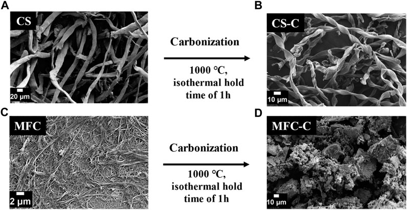
FIGURE 1. SEM images of (A) CS (cotton snippets, precursor), (B) CS-C (CS carbonized at 1,000°C for an isothermal hold time of 1 h), (C) MFC (microfibrillated cellulose, precursor), and (D) MFC-C (MFC carbonized at 1,000°C for an isothermal hold time of 1 h).
The microstructural properties of MFC-C and CS-C were evaluated using X-ray diffraction and Raman spectroscopy. The XRD patterns of both MFC-C and CS-C (Figure 2A) show broad and weak peaks representative of hard carbon samples at 24o and 45o that correspond to the (002) and (100) planes of the expanded graphite, respectively. The interlayer spacing (d002) of MFC-C and CS-C was calculated using Bragg’s Law (Cantor and Cantor, 2020). Both samples have an interlayer spacing between 3.6 Å and 4 Å suitable for Na+ intercalation (Sun et al., 2019), MFC-C has a significantly smaller interlayer spacing of 3.61 (±0.02) Å compared to CS-C with an interlayer spacing of 3.71 (±0.02) Å. The Raman spectra in Figure 2B show characteristic bands at 1,340 cm-1 (D-band or defect-induced band) and at 1,580 cm-1 (G-band or crystalline graphite band) for both the samples, which complements the XRD patterns in confirming the amorphous nature of the samples (Li et al., 2016). The ID/IG ratio of MFC-C was calculated to be 1.02 (±0.01) which is lower than that of CS-C with an ID/IG ratio of 1.10 (±0.02). Furthermore, the textural properties of both samples were studied via N2 sorption experiments (Figure 2C). For both MFC-C and CS-C, there is a hysteresis lag in the adsorption-desorption isotherms due to the presence of micropores and ultra micropores in the samples which are not easy to desorb (Ren et al., 2022). The BET surface area (calculated in the relative pressure range of 0.05–0.25 of the adsorption isotherms) of MFC-C was 22 m2 g-1 which is lower than that of CS-C with a surface area of 70 m2 g-1. However, due to the inability of N2 to access the deep pores of such microporous materials, the BET surface areas are best interpreted as relative values across the samples and not as absolute values. Additionally, the pore evolution for both MFC-C and CS-C was studied using density functional theory (DFT) pore size distribution (Figure 2D). There is a wide distribution of pores in MFC-C from as low as 1 nm micropores to 8 nm mesopores, with an average pore width of 1.4 nm. On the other hand, the pore width of CS-C is narrow ranging between 2 nm and 4 nm with an average pore width of 3.6 nm.
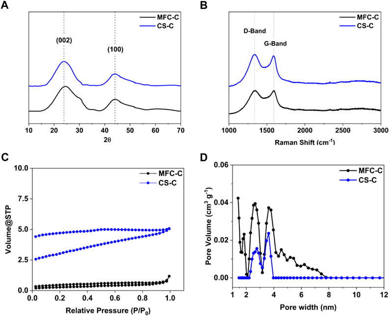
FIGURE 2. (A) XRD patterns, (B) Raman spectra, (C) N2 adsorption isotherms, and (D) DFT pore size distribution of MFC-C (MFC carbonized at 1,000°C for an isothermal hold time of 1 h) and CS-C (CS carbonized at 1,000°C for an isothermal hold time of 1 h).
Surface functionality on both MFC-C and CS-C was analyzed using X-ray photoelectron spectroscopy (XPS). From the high-resolution C 1s and O 1s XPS spectra of both the samples in Figure 3, the C/O ratio was calculated to be 8.3 (±0.1) in MFC-C and 9.9 (±0.2) in CS-C indicating the presence of a higher number of O functional groups in the MFC-C sample. Moreover, the C 1s and O 1s XPS spectra were deconvoluted to evaluate the type of carbon and oxygen species present in both samples. From the deconvoluted C 1s spectra of MFC-C and CS-C in Figures 3A,B, four carbon peaks were obtained at binding energies of 284.8 eV, 286.3 eV, 287.5 eV and 289.3 eV which correspond to C-C, C-O, C=O and O-C=O type species, respectively. This was consistent with the deconvoluted O 1s XPS spectra of MFC-C and CS-C (Figures 3C, D), with three peaks at 532.6 eV, 531.5 eV and 534 eV corresponding to C-O, C=O and O-C=O type species, respectively (Peng et al., 2021). There was not any appreciable difference between the C=O type species and C-O type species in both the samples, with a calculated C=O/C-O ratio of 0.8 in MFC-C and 0.7 in CS-C.
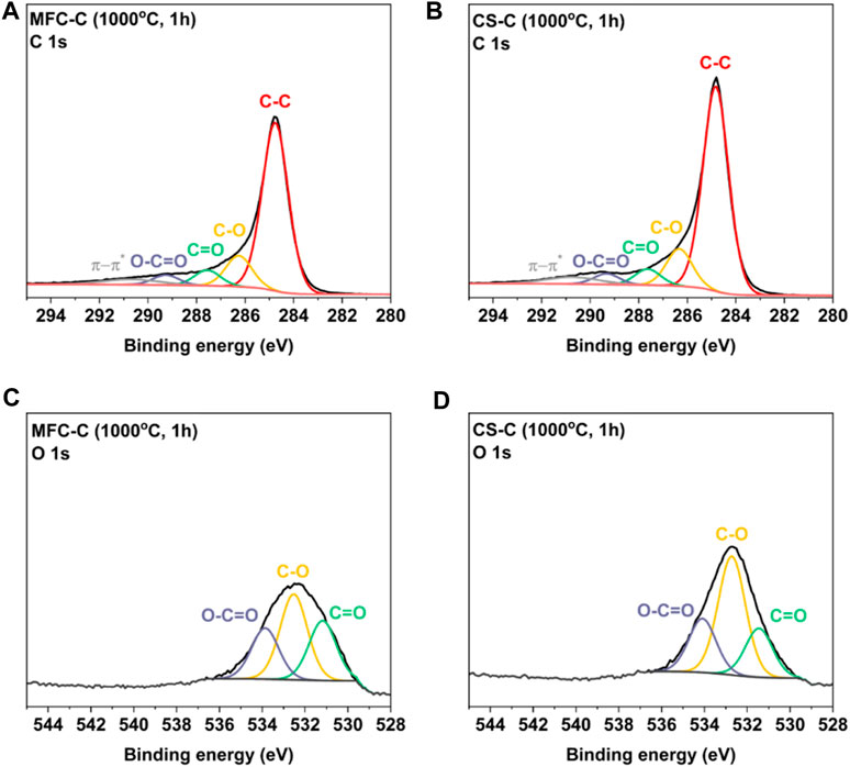
FIGURE 3. Deconvoluted C 1s XPS spectra of (A) MFC-C, (B) CS-C, and deconvoluted O 1s XPS spectra of (C) MFC-C, and (D) CS-C.
The effect of the differences in the microstructure and morphology of the MFC-C and CS-C hard carbons on their electrochemical performance was examined by testing MFC-C and CS-C anodes in Na half cells. It can be seen in Figure 4A that both MFC-C and CS-C show similar charge-discharge behavior in the 1st formation cycle. There is a feature in the potential range of 0.8–1 V which is not observable in the subsequent cycles. This is most likely related to the formation of solid electrolyte interphase (SEI) on the surface of the anode (Sun et al., 2021). The initial coulombic efficiency (ICE) of the MFC-C was measured at 73% similar to that of CS-C at 72%. However, the coulombic efficiency (CE) of the subsequent formation cycles in MFC-C (Supplementary Figure S2) is lower than that of CS-C (Supplementary Figure S3), suggesting that the SEI layer in MFC-C took longer to stabilize than the SEI in CS-C. Thus, after the 5th formation cycle (Figure 4B), MFC-C and CS-C show a similar discharge behavior (i.e., a sloping potential region above 0.1 V and a plateau region below 0.1 V) but the lower CE of MFC-C over all the formation cycles (cycled at 25 mA g-1) resulted in a lower capacity when compared to CS-C. Differences in these 5 cycles in terms of sloping potential capacity (>0.1 V), plateau potential capacity (<0.1 V) as well as total capacity are shown in Figure 4C. In the 1st cycle, MFC-C delivered a total capacity of 334 mAh g-1 with 207 mAh g-1 in the sloping potential region and 127 mAh g-1 in the plateau potential region. In comparison, CS-C delivered a slightly lesser total capacity of 327 mAh g-1 with 203 mAh g-1 in the sloping potential region and 125 mAh g-1 in the plateau potential region. However, in the subsequent cycles, MFC-C delivered lower total capacities of 244 mAh g-1 (2nd cycle), 242 mAh g-1 (3rd cycle), 239 mAh g-1 (4th cycle) and 238 mAh g-1 (5th cycle) in comparison to CS-C which delivered total capacities of 249 mAh g-1 (2nd cycle), 251 mAh g-1 (3rd cycle) and 254 mAh g-1 (for both 4th and 5th cycle). A similar trend was observed with the sloping potential capacities and plateau potential capacities for both samples. The differences between MFC-C and CS-C during the first 5 formation cycles are reflected in the long-term cycling performance as well, as seen in Figure 4D. After 100 cycles (cycling at 50 mA g-1 after 5 formation cycles at 25 mA g-1), MFC-C delivered a specific capacity of 199 mAh g-1 while CS-C delivered a higher specific capacity of 240 mAh g-1. Lower specific capacity in MFC-C compared to CS-C may be attributed to a lower interlayer spacing (d002), a lower degree of disorder (ID/IG) along with lower coulombic efficiency (CE) in the first five formation cycles that led to higher irreversible capacity loss.
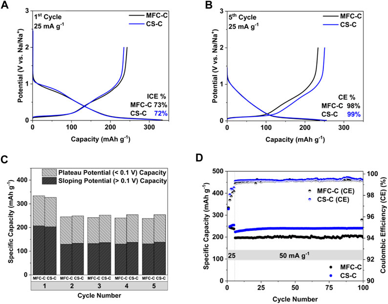
FIGURE 4. (A) 1st cycle Charge-discharge curves, (B) 5th cycle Charge-discharge curves, (C) cycling behavior in terms of total capacity, sloping potential capacity (>0.1 V), and plateau potential capacity (<0.1 V), and (D) long-term cycling performance of MFC-C and CS-C.
Cyclic voltammetry (CV) and electrochemical impedance spectroscopy (EIS) measurements were done to further understand the Na storage behavior and reaction kinetics in MFC-C and CS-C. The CV curves of the 1st formation cycle of both samples at a scan rate of 0.1 mV s-1 are shown in Figure 5A and are consistent with the 1st charge-discharge curves in Figure 4A. Both samples have a broad and large reduction peak in the 0.8–1 V range in the 1st formation cycle due to the formation and stabilization of the solid electrolyte interphase (SEI) layer, which is not seen in the subsequent cycles (Supplementary Figure S3). The 5th CV cycle for both MFC-C and CS-C is shown in Figure 5B, wherein a higher current is obtained for CS-C in comparison to MFC-C, consistent with the higher specific capacities obtained in CS-C. Following this, CV measurements were carried out at scan rates of 0.1, 0.2, 0.5, 1, 2, and 5 mV s-1 and shown in Supplementary Figure S4. For both MFC-C and CS-C, higher currents were obtained when the scan rates were increased. The power-law equation:
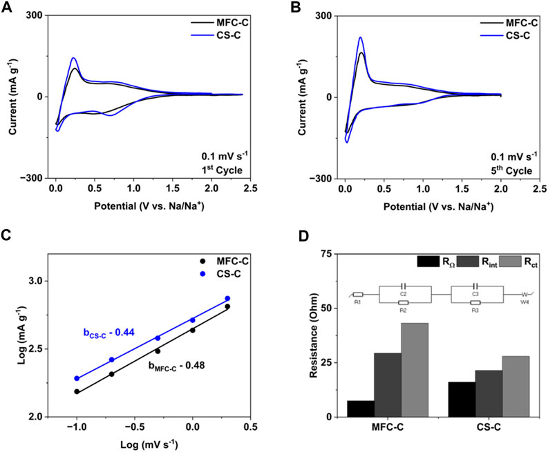
FIGURE 5. (A) 1st cycle CV curves, (B) 5th cycle CV curves, (C) log I vs. log v, (D) Resistance values obtained after fitting of EIS spectra for the samples: MFC-C and CS-C.
To further understand the interfacial properties of MFC-C and CS-C in terms of SEI formation, ex-situ 23Na and 19F MAS NMR (nuclear magnetic resonance) measurements were conducted as a semiquantitative technique to characterize the SEI. From the deconvoluted 23Na MAS NMR spectra a very weak IL residue signal was obtained at approximately – 4 ppm for both MFC-C and CS-C (Figures 6A,B) which indicated that the ionic liquid residue could not be removed completely (Sun et al., 2023). The peak at approximately 7 ppm for both MFC-C and CS-C can be assigned to NaF, a common electrolyte decomposition product considered to be present for F-containing electrolytes (Ferdousi et al., 2021; Ferdousi et al., 2022; Sun et al., 2023). In addition to the NaF resonance, an additional peak at around – 10 ppm is present for both MFC-C and CS-C. This can be explained by the formation of a Na complex (suggested to be Na2 [SO3-N-SO2F]) resulting from the partial breakdown of FSI (Ferdousi et al., 2021; Ferdousi et al., 2022). The 19F MAS NMR spectra (as shown in Supplementary Figure S6) for MFC-C and CS-C were consistent with the 23Na spectra, wherein three fluorine peaks were obtained at 52 ppm, – 79 ppm and – 225 ppm that correspond to S-F groups (from the Na-complex in the SEI layer as well as the IL electrolyte residue), C-F groups from the MAS rotor material and NaF peak from the SEI layer, respectively. Despite having similar SEI layer composition, it could be seen from the raw 23Na MAS NMR spectra of the samples in Figure 6C that the overall peak intensity of CS-C is much lower in comparison to MFC-C, consistent with a lower total amount of SEI present. This is further verified by the difference in the peak area of the 23Na MAS NMR peaks in MFC-C and CS-C, shown in Figure 6D. Evidently, for the MFC-C electrode, the combined peak area of NaF and the Na-complex is significantly higher than CS-C, indicating a greater amount of SEI formed on MFC-C (based on previous work, this would reflect a thicker SEI layer (Sun et al., 2023). This supports the EIS data discussed earlier wherein a thicker SEI layer would exhibit higher resistance as is the case for MFC. The relative contribution (%) of NaF and the Na-complex is similar in both samples with a contribution of 61% and 39% contribution, respectively in MFC-C and a contribution of 58% and 41% contribution, respectively in CS-C.
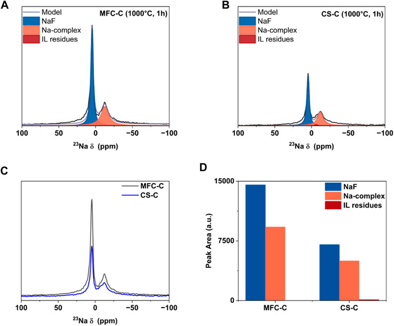
FIGURE 6. Ex-situ 23Na MAS NMR spectra of electrodes- (A) MFC-C and (B) CS-C, (C) overlayed raw 23Na MAS NMR spectra of MFC-C and CS-C, and (D) comparison of peak area of the SEI products as detected by MAS-NMR.
Conclusion
In conclusion, two different structures of cellulose, i.e., cotton snippets (CS) and microfibrillated cellulose (MFC) were used to prepare hard carbons and understand the differences in terms of their microstructure as well as electrochemical performance. Briefly, MFC-C had a lower d002 spacing of 3.61 Å, a lower degree of disorder (ID/IG of 1.02), and a large number of micropores with an average pore width of 1.4 nm, in comparison to CS-C. Additionally, ex-situ MAS NMR analysis of both the cycled MFC-C and CS-C electrodes revealed a stable and conductive SEI layer composed of Na-F and a Na-complex, suggested to be Na2 [SO3-N-SO2F]. Based on the semi-quantitative NMR analysis and the EIS data, the amount of the SEI layer is believed to be greater in MFC-C than in CS-C, resulting in slower Na+ transfer kinetics and overall cell performance. While both samples reported an ICE of 72%–73%, MFC-C delivered a capacity of 199 mAh g-1 while CS-C delivered a capacity of 240 mAh g-1 after 100 cycles (cycling at 50 mA g-1 after 5 formation cycles at 25 mA g-1). Thus, investigating the hard carbon microstructure arising from different morphologies of the same structure and its impact on Na storage performance can help enhance the design and optimization of such anode materials for large-scale NIB applications.
Data availability statement
The original contributions presented in the study are included in the article/Supplementary Material, further inquiries can be directed to the corresponding authors.
Author contributions
HR: Conceptualization, Writing–review and editing, Data curation, Writing–original draft. JS: Writing–review and editing, Supervision. IG: Writing–review and editing, Data curation, Formal Analysis. YH: Data curation, Writing–review and editing. RR: Writing–review and editing, Supervision. MF: Supervision, Writing–review and editing, Resources. NB: Supervision, Writing–review and editing, Conceptualization, Funding acquisition.
Funding
The author(s) declare financial support was received for the research, authorship, and/or publication of this article. The authors acknowledge that this work was also supported by the Australian Research Council Training Centre for Future Energy Storage Technologies (IC180100049), funded by the Australian Government.
Acknowledgments
The authors acknowledge the Australian government for their support through an Australian Government Research Training Program Scholarship; and acknowledge that this work was also supported by the Australian Research Council Training Centre for Future Energy Storage Technologies (IC180100049), funded by the Australian Government.
Conflict of interest
The authors declare that the research was conducted in the absence of any commercial or financial relationships that could be construed as a potential conflict of interest.
Publisher’s note
All claims expressed in this article are solely those of the authors and do not necessarily represent those of their affiliated organizations, or those of the publisher, the editors and the reviewers. Any product that may be evaluated in this article, or claim that may be made by its manufacturer, is not guaranteed or endorsed by the publisher.
Supplementary material
The Supplementary Material for this article can be found online at: https://www.frontiersin.org/articles/10.3389/fbael.2023.1330448/full#supplementary-material
References
Allesch, A., and Brunner, P. H. (2014). Assessment methods for solid waste management: a literature review. Waste Manag. Res. J. a Sustain. Circular Econ. 32, 461–473. doi:10.1177/0734242x14535653
Asaadi, S., Hummel, M., Hellsten, S., Härkäsalmi, T., Ma, Y., Michud, A., et al. (2016). Renewable high-performance fibers from the chemical recycling of cotton waste utilizing an ionic liquid. ChemSusChem 9, 3250–3258. doi:10.1002/cssc.201600680
Cantor, B., and Cantor, B. (2020). “24Bragg’s law: diffraction,” in The equations of materials (Oxford, UK: Oxford University Press).
Chen, W., Yu, H., Lee, S.-Y., Wei, T., Li, J., and Fan, Z. (2018). Nanocellulose: a promising nanomaterial for advanced electrochemical energy storage. Chem. Soc. Rev. 47, 2837–2872. doi:10.1039/c7cs00790f
Chen, X., Liu, C., Fang, Y., Ai, X., Zhong, F., Yang, H., et al. (2022). Understanding of the sodium storage mechanism in hard carbon anodes. Carbon Energy 4, 1133–1150. doi:10.1002/cey2.196
Darwiche, A., Marino, C., Sougrati, M. T., Fraisse, B., Stievano, L., and Monconduit, L. (2012). Better cycling performances of bulk Sb in Na-ion batteries compared to Li-ion systems: an unexpected electrochemical mechanism. J. Am. Chem. Soc. 134, 20805–20811. doi:10.1021/ja310347x
Dou, X., Hasa, I., Saurel, D., Vaalma, C., Wu, L., Buchholz, D., et al. (2019). Hard carbons for sodium-ion batteries: structure, analysis, sustainability, and electrochemistry. Mater. Today 23, 87–104. doi:10.1016/j.mattod.2018.12.040
Fan, M., Chen, Y., Xie, Y., Yang, T., Shen, X., Xu, N., et al. (2016). Half-cell and full-cell applications of highly stable and binder-free sodium ion batteries based on Cu3P nanowire anodes. Adv. Funct. Mater. 26, 5019–5027. doi:10.1002/adfm.201601323
Fang, Y., Luan, D., Chen, Y., Gao, S., and Lou, X. W. (2020). Rationally designed three-layered Cu2S@carbon@MoS2 hierarchical nanoboxes for efficient sodium storage. Angew. Chem. Int. Ed. 59, 7178–7183. doi:10.1002/anie.201915917
Ferdousi, S. A., O’dell, L. A., Hilder, M., Barlow, A. J., Armand, M., Forsyth, M., et al. (2021). SEI formation on sodium metal electrodes in superconcentrated ionic liquid electrolytes and the effect of additive water. ACS Appl. Mater. Interfaces 13, 5706–5720. doi:10.1021/acsami.0c18119
Ferdousi, S. A., O’dell, L. A., Sun, J., Hora, Y., Forsyth, M., and Howlett, P. C. (2022). High-performance cycling of Na metal anodes in phosphonium and pyrrolidinium fluoro(sulfonyl)imide based ionic liquid electrolytes. ACS Appl. Mater. Interfaces 14, 15784–15798. doi:10.1021/acsami.1c24812
Flygare, M., and Svensson, K. (2019). Quantifying crystallinity in carbon nanotubes and its influence on mechanical behaviour. Mater. Today Commun. 18, 39–45. doi:10.1016/j.mtcomm.2018.11.003
Hsieh, Y. L. (2007). “1 - chemical structure and properties of cotton,” in Cotton. Editors S. Gordon, and Y. L. Hsieh (Sawston, UK: Woodhead Publishing), 3–34.
Huang, C., Ji, H., Yang, Y., Guo, B., Luo, L., Meng, Z., et al. (2020). TEMPO-oxidized bacterial cellulose nanofiber membranes as high-performance separators for lithium-ion batteries. Carbohydr. Polym. 230, 115570. doi:10.1016/j.carbpol.2019.115570
Hwang, J.-Y., Myung, S.-T., and Sun, Y.-K. (2017). Sodium-ion batteries: present and future. Chem. Soc. Rev. 46, 3529–3614. doi:10.1039/c6cs00776g
Kim, Y., Kim, Y., Choi, A., Woo, S., Mok, D., Choi, N.-S., et al. (2014). Tin phosphide as a promising anode material for Na-ion batteries. Adv. Mater. 26, 4139–4144. doi:10.1002/adma.201305638
Kim, Y. E., Yeom, S. J., Lee, J.-E., Kang, S., Kang, H., Lee, G.-H., et al. (2020). Structure-dependent sodium ion storage mechanism of cellulose nanocrystal-based carbon anodes for highly efficient and stable batteries. J. Power Sources 468, 228371. doi:10.1016/j.jpowsour.2020.228371
Lee, B.-M., Eom, J.-J., Baek, G. Y., Hong, S.-K., Jeun, J.-P., Choi, J.-H., et al. (2019). Cellulose non-woven fabric-derived porous carbon films as binder-free electrodes for supercapacitors. Cellulose 26, 4529. doi:10.1007/s10570-019-02380-6
Li, G., Ouyang, T., Xiong, T., Jiang, Z., Adekoya, D., Wu, Y., et al. (2021). All-carbon-frameworks enabled thick electrode with exceptional high-areal-capacity for Li-Ion storage. Carbon 174, 1–9. doi:10.1016/j.carbon.2020.12.018
Li, Y., Hu, Y.-S., Titirici, M.-M., Chen, L., and Huang, X. (2016). Hard carbon microtubes made from renewable cotton as high-performance anode material for sodium-ion batteries. Adv. Energy Mater. 6, 1600659. doi:10.1002/aenm.201600659
Lindström, H., Södergren, S., Solbrand, A., Rensmo, H., Hjelm, J., Hagfeldt, A., et al. (1997). Li+ ion insertion in TiO2 (anatase). 2. Voltammetry on nanoporous films. J. Phys. Chem. B 101, 7717–7722. doi:10.1021/jp970490q
Luo, W., Schardt, J., Bommier, C., Wang, B., Razink, J., Simonsen, J., et al. (2013). Carbon nanofibers derived from cellulose nanofibers as a long-life anode material for rechargeable sodium-ion batteries. J. Mater. Chem. A 1, 10662. doi:10.1039/c3ta12389h
Ma, Y., Zeng, B., Wang, X., and Byrne, N. (2019). Circular textiles: closed loop fiber to fiber wet spun process for recycling cotton from denim. ACS Sustain. Chem. Eng. 7, 11937–11943. doi:10.1021/acssuschemeng.8b06166
Nguyen, H. K., Bae, J., Hur, J., Park, S. J., Park, M. S., and Kim, I. T. (2019). Tailoring of aqueous-based carbon nanotube–nanocellulose films as self-standing flexible anodes for lithium-ion storage. Nanomaterials 9, 655–4991. doi:10.3390/nano9040655
Oh, S.-I., Kim, J.-C., and Kim, D.-W. (2019). Cellulose-derived tin-oxide-nanoparticle-embedded carbon fibers as binder-free flexible Li-ion battery anodes. Cellulose 26, 2557–2571. doi:10.1007/s10570-019-02258-7
Park, K., Han, D., Kim, H., Chang, W.-S., Choi, B., Anass, B., et al. (2014). Characterization of a P2-type chelating-agent-assisted Na2/3Fe1/2Mn1/2O2 cathode material for sodium-ion batteries. RSC Adv. 4, 22798–22802. doi:10.1039/c4ra01391c
Peng, S., Han, X., Li, L., Zhu, Z., Cheng, F., Srinivansan, M., et al. (2016). Unique cobalt sulfide/reduced graphene oxide composite as an anode for sodium-ion batteries with superior rate capability and long cycling stability. Small 12, 1359–1368. doi:10.1002/smll.201502788
Peng, Y., Chen, Z., Zhang, R., Zhou, W., Gao, P., Wu, J., et al. (2021). Oxygen-containing functional groups regulating the carbon/electrolyte interfacial properties toward enhanced K+ storage. Nano-Micro Lett. 13, 192. doi:10.1007/s40820-021-00722-3
Philippe, B., Valvo, M., Lindgren, F., Rensmo, H., and Edström, K. (2014). Investigation of the electrode/electrolyte interface of Fe2O3 composite electrodes: Li vs Na batteries. Chem. Mater. 26, 5028–5041. doi:10.1021/cm5021367
Rahman, M. M., Sultana, I., Chen, Z., Srikanth, M., Li, L. H., Dai, X. J., et al. (2015). Ex situ electrochemical sodiation/desodiation observation of Co3O4 anchored carbon nanotubes: a high performance sodium-ion battery anode produced by pulsed plasma in a liquid. Nanoscale 7, 13088–13095. doi:10.1039/c5nr03335g
Ravikovitch, P. I., Haller, G. L., and Neimark, A. V. (1998). Density functional theory model for calculating pore size distributions: pore structure of nanoporous catalysts. Adv. colloid interface Sci. 76-77, 203–226. doi:10.1016/s0001-8686(98)00047-5
Ren, J., Weng, H., Li, B., Chen, F., Liu, J., and Song, Z. (2022). The influence mechanism of pore structure of tectonically deformed coal on the adsorption and desorption hysteresis. Front. Earth Sci. 10. doi:10.3389/feart.2022.841353
Saurel, D., Orayech, B., Xiao, B., Carriazo, D., Li, X., and Rojo, T. (2018). From charge storage mechanism to performance: a roadmap toward high specific energy sodium-ion batteries through carbon anode optimization. Adv. Energy Mater. 8, 1703268. doi:10.1002/aenm.201703268
Scherrer, P. (1918). Nachrichten von der Gesellschaft der Wissenschaften zu Göttingen. Mathematisch-Physikalische Kl. 2, 98–100.
Shen, F., Zhu, H., Luo, W., Wan, J., Zhou, L., Dai, J., et al. (2015). Chemically crushed wood cellulose fiber towards high-performance sodium-ion batteries. ACS Appl. Mater. Interfaces 7, 23291–23296. doi:10.1021/acsami.5b07583
Simone, V., Boulineau, A., De Geyer, A., Rouchon, D., Simonin, L., and Martinet, S. (2016). Hard carbon derived from cellulose as anode for sodium ion batteries: dependence of electrochemical properties on structure. J. Energy Chem. 25, 761–768. doi:10.1016/j.jechem.2016.04.016
Sottmann, J., Herrmann, M., Vajeeston, P., Hu, Y., Ruud, A., Drathen, C., et al. (2016). How crystallite size controls the reaction path in nonaqueous metal ion batteries: the example of sodium bismuth alloying. Chem. Mater. 28, 2750–2756. doi:10.1021/acs.chemmater.6b00491
Sun, J., Gunathilaka, I. E., O'dell, L. A., Howlett, P. C., and Forsyth, M. (2023). High-rate formation protocol enables a high ionic conductivity SEI for sodium-ion batteries. J. Power Sources 554, 232298. doi:10.1016/j.jpowsour.2022.232298
Sun, J., O’dell, L. A., Armand, M., Howlett, P. C., and Forsyth, M. (2021). Anion-derived solid-electrolyte interphase enables long life Na-ion batteries using superconcentrated ionic liquid electrolytes. ACS Energy Lett. 6, 2481–2490. doi:10.1021/acsenergylett.1c00816
Sun, J., Rakov, D., Wang, J., Hora, Y., Laghaei, M., Byrne, N., et al. (2022). Sustainable free-standing electrode from biomass waste for sodium-ion batteries. ChemElectroChem 9, e202200382. doi:10.1002/celc.202200382
Sun, N., Guan, Z., Liu, Y., Cao, Y., Zhu, Q., Liu, H., et al. (2019). Extended “adsorption–insertion” model: a new insight into the sodium storage mechanism of hard carbons. Adv. Energy Mater. 9, 1901351. doi:10.1002/aenm.201901351
Tianhao, W., Wentao, Z., Shujuan, Y., Weiqian, T., and Liping, Z. (2020). Regenerated bamboo-derived cellulose fibers/RGO-based composite for high-performance supercapacitor electrodes. IOP Conf. Ser. Mater. Sci. Eng. 735, 1.
Wang, J., Eng, C., Chen-Wiegart, Y.-C. K., and Wang, J. (2015). Probing three-dimensional sodiation–desodiation equilibrium in sodium-ion batteries by in situ hard X-ray nanotomography. Nat. Commun. 6, 7496. doi:10.1038/ncomms8496
Wang, J., Polleux, J., Lim, J., and Dunn, B. (2007). Pseudocapacitive contributions to electrochemical energy storage in TiO2 (anatase) nanoparticles. J. Phys. Chem. C 111, 14925–14931. doi:10.1021/jp074464w
Xiong, T., Yao, X., Adekoya, D., Yang, H., and Sadeeq Balogun, M. (2023). Scaffold-regulation buffered MoS2 anode kinetics for high-performance Na-/K-ion storage. J. Mater. Sci. Technol. 145, 14–24. doi:10.1016/j.jmst.2022.10.051
Yamamoto, H., Muratsubaki, S., Kubota, K., Fukunishi, M., Watanabe, H., Kim, J., et al. (2018). Synthesizing higher-capacity hard-carbons from cellulose for Na- and K-ion batteries. J. Mater. Chem. A 6, 16844–16848. doi:10.1039/c8ta05203d
Yuan, S., Huang, X.-L., Ma, D.-L., Wang, H.-G., Meng, F.-Z., and Zhang, X.-B. (2014). Engraving copper foil to give large-scale binder-free porous CuO arrays for a high-performance sodium-ion battery anode. Adv. Mater. 26, 2273–2279. doi:10.1002/adma.201304469
Zhang, H., Huang, Y., Ming, H., Cao, G., Zhang, W., Ming, J., et al. (2020). Recent advances in nanostructured carbon for sodium-ion batteries. J. Mater. Chem. A 8, 1604–1630. doi:10.1039/c9ta09984k
Zhang, T., Yang, L., Yan, X., and Ding, X. (2018). Recent advances of cellulose-based materials and their promising application in sodium-ion batteries and capacitors. Small (Weinheim der Bergstrasse, Ger. 14, e1802444. doi:10.1002/smll.201802444
Keywords: hard carbons, waste biomass, sodium, energy storage, solid electrolyte interface
Citation: Sarma HR, Sun J, Gunathilaka IE, Hora Y, Rajkhowa R, Forsyth M and Byrne N (2024) Effect of precursor morphology of cellulose-based hard carbon anodes for sodium-ion batteries. Front. Batteries Electrochem. 2:1330448. doi: 10.3389/fbael.2023.1330448
Received: 30 October 2023; Accepted: 11 December 2023;
Published: 04 January 2024.
Edited by:
Xingcheng Xiao, General Motors, United StatesCopyright © 2024 Sarma, Sun, Gunathilaka, Hora, Rajkhowa, Forsyth and Byrne. This is an open-access article distributed under the terms of the Creative Commons Attribution License (CC BY). The use, distribution or reproduction in other forums is permitted, provided the original author(s) and the copyright owner(s) are credited and that the original publication in this journal is cited, in accordance with accepted academic practice. No use, distribution or reproduction is permitted which does not comply with these terms.
*Correspondence: Nolene Byrne, nolene.byrne@deakin.edu.au; Maria Forsyth, maria.forsyth@deakin.edu.au