Patient-Specific Finite Element Models of Posterior Pedicle Screw Fixation: Effect of Screw’s Size and Geometry
 Marco Sensale1,2,3
  Tanguy Vendeuvre4,5 Christoph Schilling6 Thomas Grupp6,7 Michel Rochette1
  Enrico Dall’Ara2,3*
- 1Ansys France, Lyon, France
- 2Department of Oncology and Metabolism, Mellanby Centre for Musculoskeletal Research, University of Sheffield, Sheffield, United Kingdom
- 3INSIGNEO Institute for in Silico Medicine, University of Sheffield, Sheffield, United Kingdom
- 4Spine and Neuromodulation Functional Unit, Poitiers University Hospital, Poitiers, France
- 5PRISMATICS Lab (Predictive Research in Spine/Neuromodulation Management and Thoracic Innovation/Cardiac Surgery), Poitiers University Hospital, Poitiers, France
- 6Aesculap AG, Research and Development, Tuttlingen, Germany
- 7Department of Orthopaedic Surgery, Physical Medicine and Rehabilitation, Ludwig Maximilians University of Munich, Munich, Germany
Pedicle screw fixation is extensively performed to treat spine injuries or diseases and it is common for thoracolumbar fractures. Post-operative complications may arise from this surgery leading to back pain or revisions. Finite element (FE) models could be used to predict the outcomes of surgeries but should be verified when both simplified and realistic designs of screws are used. The aim of this study was to generate patient-specific Computed Tomography (CT)-based FE models of human vertebrae with two pedicle screws, verify the models, and use them to evaluate the effect of the screws’ size and geometry on the mechanical properties of the screws-vertebra structure. FE models of the lumbar vertebra implanted with two pedicle screws were created from anonymized CT-scans of three patients. Compressive loads were applied to the head of the screws. The mesh size was optimized for realistic and simplified geometry of the screws with a mesh refinement study. Finally, the optimal mesh size was used to evaluate the sensitivity of the model to changes in screw’s size (diameter and length) and geometry (realistic or simplified). For both simplified and realistic models, element sizes of 0.6 mm in the screw and 1.0 mm in the bone allowed to obtain relative differences of approximately 5% or lower. Changes in screw’s length resulted in 4–10% differences in maximum deflection, 1–6% differences in peak stress in the screws, 10–22% differences in mean strain in the bone around the screw; changes in screw’s diameter resulted in 28–36% differences in maximum deflection, 6–27% differences in peak stress in the screws, and 30–47% differences in mean strain in the bone around the screw. The maximum deflection predicted with realistic or simplified screws correlated very well (R2 = 0.99). The peak stress in screws with realistic or simplified design correlated well (R2 = 0.82) but simplified models underestimated the peak stress. In conclusion, the results showed that the diameter of the screw has a major role on the mechanics of the screw-vertebral structure for each patient. Simplified screws can be used to estimate the mechanical properties of the implanted vertebrae, but the systematic underestimation of the peak stress should be considered when interpreting the results from the FE analyses.
Introduction
In the lumbar spine, pedicle screw fixation is the most widespread technique to achieve spinal fusion and stabilization (Verma et al., 2016). In 2008, approximately 415,000 spinal fusion surgeries were performed in the United States alone (Rajaee et al., 2012). The global pedicle screw system market has been predicted to increase of about 32% from 2018 to 2025 as reported by Fior Markets (Fior Markets, 2020). Pedicle screw fixation is the standard surgical procedure to treat different diseases of the spine, in particular, it is common for thoracolumbar fractures.
Despite the extensive use of pedicle screws in the current clinical practice, screw loosening and screw breakage are recurring mechanical complications of spinal fixation that can bring to a revision surgery in about 6% of cases (Prud’homme et al., 2015; Bredow et al., 2016). For this reason, surgery-related parameters should be optimized to improve the outcomes of this surgery. While surgeons decide the optimal size, insertion point and orientation of screws based on anatomical measurements on CT-images, finite element (FE) models are efficient tools to mechanically assess the stability of different configurations of the instrumented spine under different loading conditions. FE models of the vertebra should take into account different parameters related to the bone geometry, bone tissue heterogeneity, different boundary conditions, and before clinical applications they should be verified and validated [see for example (Assessing Credibility of Computational Modeling through Verification and Validation: Application to Medical Devices–ASME)]. Many studies assessed the optimal fixation to treat a burst fracture by simulating with FE models a system composed of three vertebrae and two intervertebral discs implanted with different configurations of rod and screws (e.g., monolateral vs. bilateral, short segment vs. long segment) (Li et al., 2014; Elmasry et al., 2017; Su et al., 2018; Wang et al., 2019). Other studies focused on the vertebra-screws interactions and proposed FE models validated with experimental measures: FE models were found to be good predictors of pull-out strength and stiffness obtained by experimental tests better than apparent density estimated from CT images (Abbeele et al., 2018; Chevalier et al., 2018; Widmer et al., 2020). The screw size and other insertion-related parameters have been tested with linear FE models (Qi et al., 2011; Newcomb et al., 2017), with non-linear FE models (material non-linearities, contact mechanics) (Chen et al., 2003; Bianco et al., 2017, 2019; Molinari et al., 2021), or assuming the bone as heterogeneous material with elastic properties driven by the local bone mineral density (BMD) (Matsukawa et al., 2016, 2020; Biswas et al., 2019; Molinari et al., 2021). In most cases a realistic screw geometry was used and only in a few studies the simplified geometry of the screw was modeled (Li et al., 2014; Su et al., 2018). The usage of simplified screws would enable the optimization and automation of the modeling procedure to evaluate vertebral and screws properties, if used in combination with morphing and reduced model order techniques (Campbell and Petrella, 2016). Although FE models of the instrumented spine are often proposed as tools for planning pedicle screw fixations to predict the optimal screw size and orientation for a given patient, little is known about the capability of predicting the biomechanical properties of the screw and of the vertebra if simplified or realistic screws are used. In particular, to the authors’ knowledge, a comprehensive assessment of the effect of the mesh size and the sensitivity of the models to the screw size and geometry, in terms of stress in the screw, strain in the heterogeneous bone, and deflection of the screw within the bone, has not been reported in the literature yet. This gap in the literature makes it difficult to compare the outcomes from different studies and understanding the potential of the FE models in evaluating the biomechanics of the implanted vertebrae.
The aim of this study was to verify and evaluate the sensitivity of subject specific FE models of the vertebra with two pedicle screws for different sizes of the implant and in case of realistic and simplified geometry of the screw.
Materials and Methods
Anonymized CT-scans of the thoracolumbar spine of three patients were collected. One vertebra per patient was segmented, converted to a FE model, virtually implanted with pedicle screws, and vertical loads were applied to the head of the screws, perpendicular to their axis. A mesh refinement study for realistic or simplified geometry of the screws was performed to choose the optimal mesh size that was used to evaluate the sensitivity of the model to changes in screw’s size (diameter and length) and geometry (realistic or simplified). An overview of the study is presented in Figure 1.
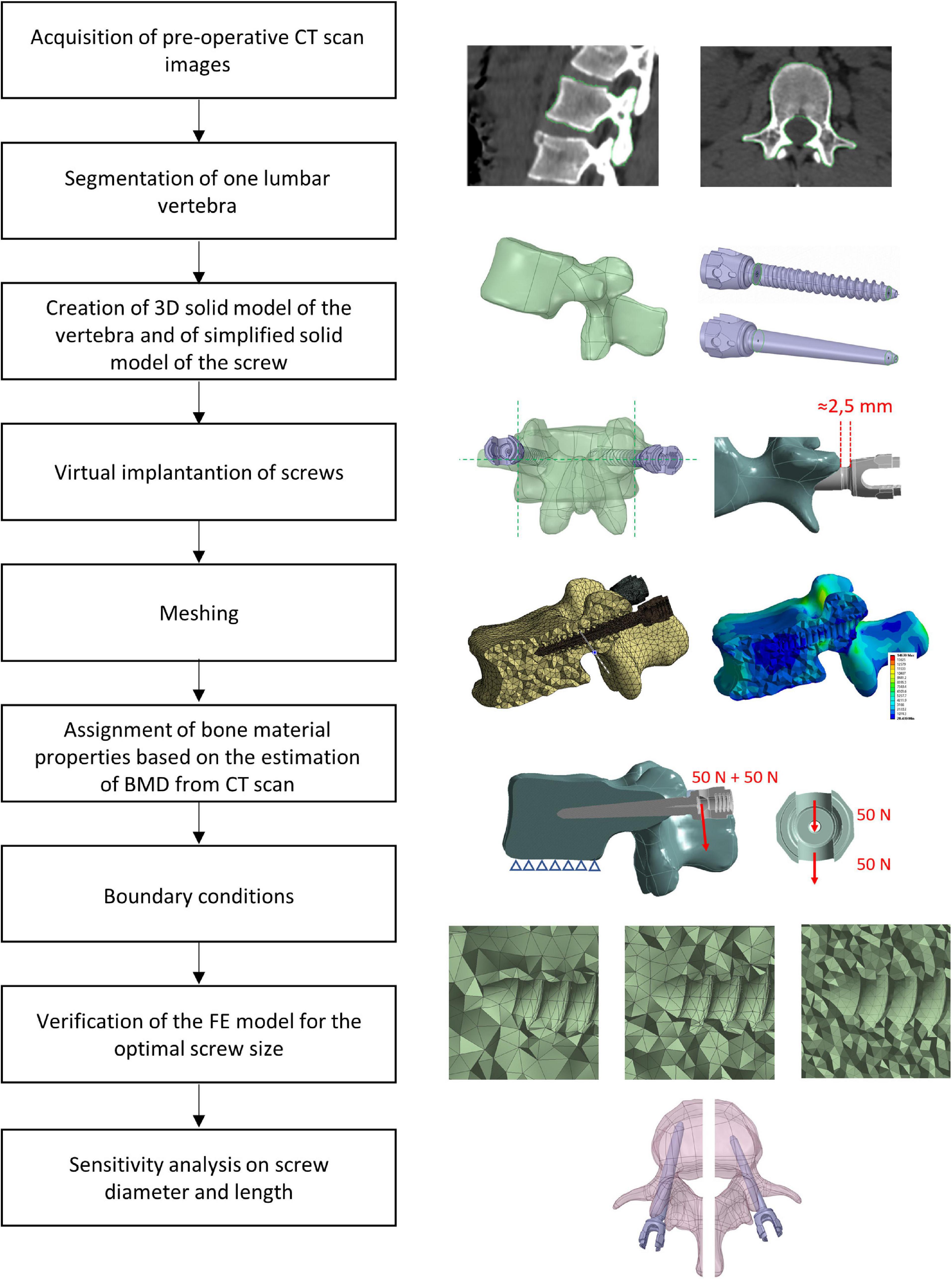
Figure 1. Workflow used to generate, verify, and test the sensitivity of heterogeneous FE models of one vertebra implanted with two pedicle screws.
Imaging and Image Processing
Three anonymized clinical pre-operative CT-scans of the thoracolumbar spine of three patients were analyzed. The scans were previously acquired at the University Hospital Centre (CHU) of Poitiers (France) and transferred only after anonymization (CHU86-RECH-R2020-02-01). These patients were treated with a posterior pedicle screw fixation for different reasons: two patients reported a vertebral fracture at L1 (Patients #1 and #3), one patient had osteoarthritis (Patients #2). The scanning parameters are reported in Table 1. In order to simplify the sensitivity study one vertebra with similar size was selected from each patient (L2, L3, and L4 for Patient #1, Patient #2, and Patient #3, respectively). The relative difference in the mean CT based BMD in the vertebral bodies was 21% between Patient #1 and Patient #2 and −24% between Patient #1 and Patient #3.
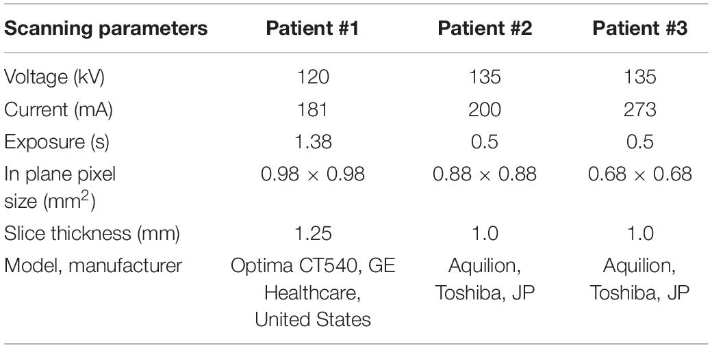
Table 1. Parameters of acquisition of CT-scan images for the three patients.
The pedicle widths and the distances between the approximated insertion points and the anterior wall of the vertebral body were measured in a cross-section corresponding to the approximated insertion points and including the longitudinal axes of the screws. From these measurements, and based on the advice of an experienced surgeon, it was concluded that the size of the vertebrae was ideal for the insertion of pedicle screws with diameter (D) equal to 6.5 mm and length (L) equal to 45 mm. The shape of the vertebrae was reconstructed by manual image segmentation of the CT cross-sections (3D Slicer, v4.10.1) (Fedorov et al., 2012). The resulting mask was smoothed with a Laplacian smoothing. The number of iterations was adjusted in order to preserve the geometric features while avoiding shrinkage of the volume, which was verified by visual inspection of the overlapped CT images and mask.
Generation of the FE Model
The segmented vertebrae were exported as surface meshes (STL) and imported in the 3D modeling software Ansys® SpaceClaim Release 20.2 (Ansys Inc., Canonsburg, PA, United States). Through a reverse engineering process (“SkinSurface” command), a 3D solid model of each vertebra was reconstructed. The surface at the bottom of the model, representative of the inferior endplate, was used to apply the boundary conditions.
Afterward, the insertion of two pedicle screws (Aesculap® S4® Element MIS Monoaxial) was simulated. The realistic geometry of the implant was imported as STP file. Nine different sizes of pedicle screws available on the market were tested including D equal to 5.5, 6.5, or 7.5 mm and L equal to 45, 50, or 55 mm. Nine simplified screws with a smooth conic body without the thread were also generated to evaluate how the thread affected the loading distribution and deformation within the vertebra-screws construct. The solid model of the simplified screws was obtained from each of the nine realistic screws as following. The head of the screw until the end of the junction with the conic feature where the thread begins, and the last portion of the screw after the end of the thread were kept from the original realistic design. The two circular exposed sections were then connected with a conic surface (Figure 2). The realistic screws with the largest size (D = 7.5 mm, L = 50 mm) were virtually inserted at the pedicles by a Boolean subtraction. The insertion point was determined by following medical guidelines (Gertzbein and Robbins, 1990), which consist of finding the intersection point between a horizontal line passing through the transverse processes and a vertical line adjacent to the lateral border of the superior articular process. Screws were positioned parallel to the superior endplate, converging to the center of the vertebral body, keeping a distance of approximately 2.5 mm between the head of the screw and the superior articular processes (Figure 1). All other realistic and simplified screws were aligned to the position of the largest screws by registering their head, which were the same for every implant. Boolean subtraction from the original vertebra was applied for each pair of screws. In total eighteen models per vertebra were generated, nine with realistic geometries and nine with simplified geometries.
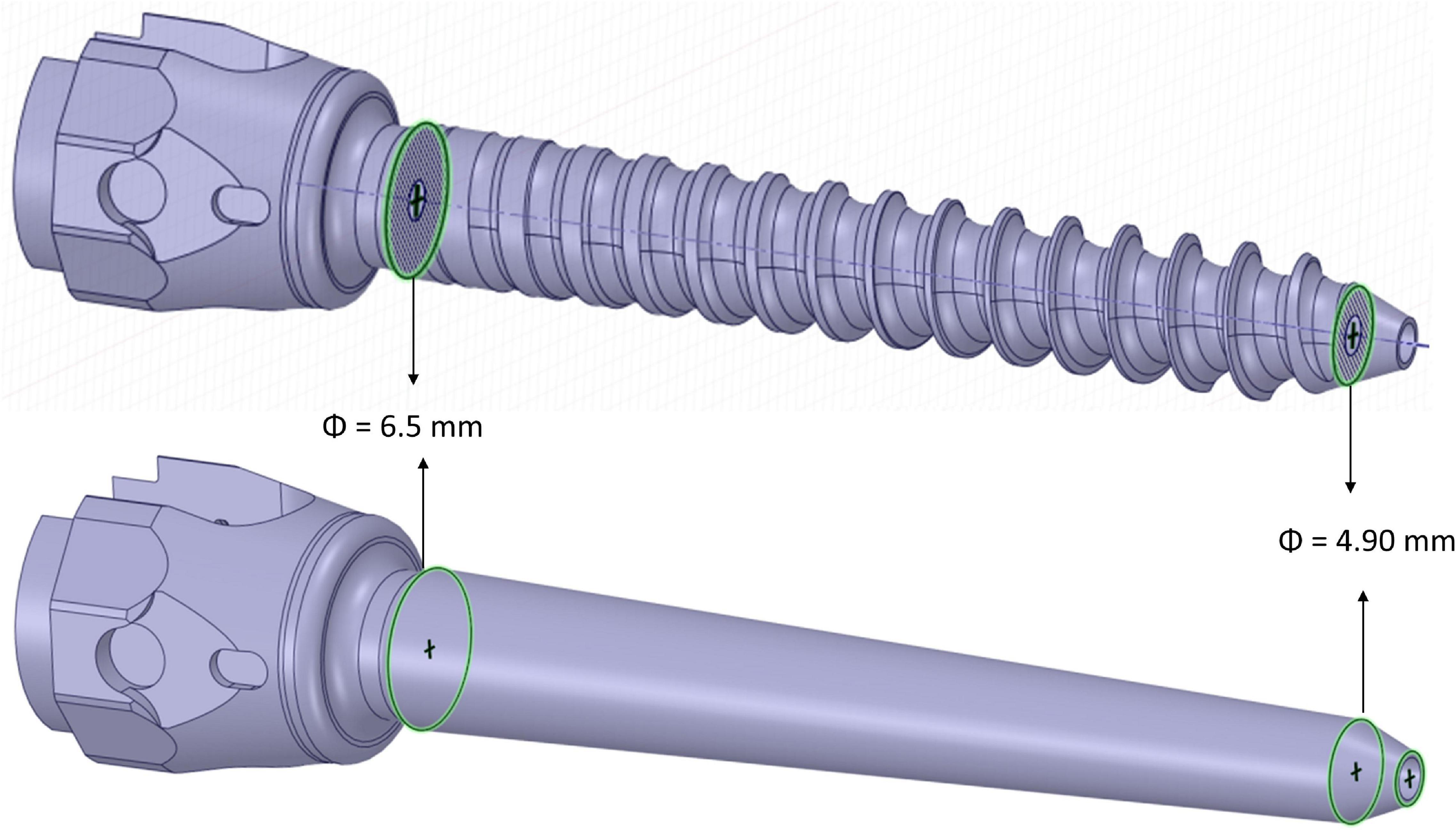
Figure 2. 3D CAD models of simplified (bottom) and realistic (top) screws.
Each vertebra-screws construct was imported in Ansys® Mechanical Enterprise Release 20.2 (Ansys Inc., Canonsburg, PA, United States) for meshing. The vertebra and the screws were meshed separately with tetrahedral quadratic elements (T10). For the vertebra, a uniform meshing algorithm was used so that the CT-scan grid was sampled uniformly during the definition of material properties of the bone. The element size was defined based on a mesh convergence study (see section “Generation of the FE Model”). A bonded contact was considered at the interface between the screws and the vertebra.
Bone was modeled as isotropic and heterogeneous material with Young’s modulus depending on the local BMD estimated from the CT images. In absence of an experimental densitometric calibration, the Hounsfield units were considered equal to BMD equivalent values (ρQCT), using a scale factor to convert the physical units to g/cm3. This assumption was considered acceptable for the goal of this study, which is focused on the verification and sensitivity analysis of the models. From the BMD equivalent density, the apparent density (ρApp) was obtained through Eq. 1 (Schileo et al., 2008):
The Young’s modulus was then calculated using the density-elasticity experimental equation specific for thoraco-lumbar vertebrae (Eq. 2) (Morgan et al., 2003):
The Poisson’s ratio of the bone was set to νbone = 0.3 (Wirtz et al., 2000). The values of Ebone were calculated and assigned for each element by using the Bonemat software (Taddei et al., 2007). The screw was considered isotropic and homogeneous with Young’s modulus and Poisson’s ratio of Titanium: Escrew = 102 GPa, νscrew = 0.36 (Niinomi and Boehlert, 2015).
The model was loaded with a quasi-static uniformly distributed force of 200 N (100 N per screw) applied to the head of the screw in a direction perpendicular to the longitudinal axis of the screw and perpendicular to the superior endplate, toward the caudal direction (Chen et al., 2003; Biswas et al., 2019; Figure 1). The force was equally distributed between the two surfaces of the head of the screw that would interact with the rod (50 N on each surface) (Figure 1). This load configuration aimed to represent the load exercised by the upper chest on the most inferior vertebra of a short-segment pedicle screw construct and transmitted by a rod that would be tightened in a direction perpendicular to the screw axis as estimated in an in-vivo study (Rohlmann et al., 1997). However, it should be noted that the model has a linear behavior and that the results of simulations were interpreted relative to the optimal configuration, therefore the magnitude of the load is not critical. In addition, the nodes of the inferior endplate of the vertebral body were fixed in all three directions (Chen et al., 2003). ANSYS® Mechanical Enterprise Release 20.2 (Ansys Inc., Canonsburg, PA, United States) was used to solve the analysis. A workstation with processor model Intel(R) Xeon(R) CPU E5-2690 v3, 2.60 GHz was used. The analysis was run in parallel processing on 4 CPU Cores.
Mesh Refinement Study
For each patient, the model configuration corresponding to the optimal screw size (D = 6.5 mm, L = 45 mm) as advised by surgeons was tested for verification purposes. A mesh convergence study was conducted to estimate the optimal mesh size. The element size was changed separately in the bone and pedicle screws. Six maximum element sizes were tested for the screws between 0.4 and 1.2 mm while keeping the element size in the bone constant and equal to 1 mm. A maximum element size larger than 1.2 mm resulted in an inaccurate discretization of the circular cavity of the screw’s body; the inferior boundary was considered at 0.4 mm based on the dimension of the smaller thread in the realistic screw (Table 2).
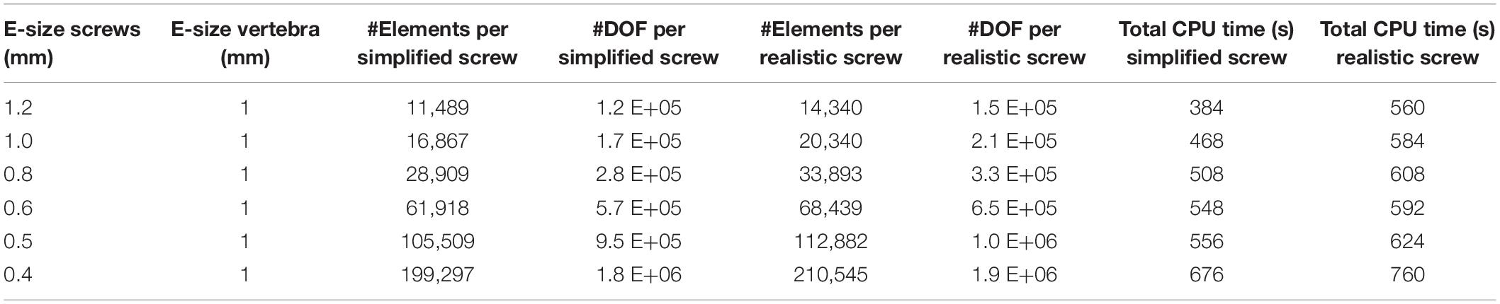
Table 2. Number of Elements and Degrees of Freedom per screw, averaged over the three patients, for six element sizes tested for the screws (the maximum element size is reported), in models with simplified or realistic screws; Total CPU time (time * number of CPU Cores) to solve models with simplified or realistic screws.
Moreover, maximum element sizes in the bone between 0.9 and 3 mm were tested for the finest mesh of the screw (0.4 mm) (Table 3). The lowest element size was to the voxel size of the CT-scan images of the three patients.
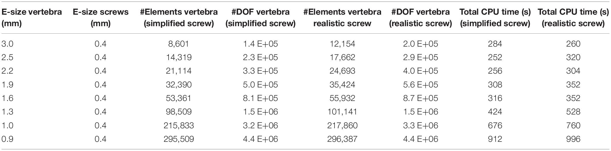
Table 3. Number of Elements and Degrees of Freedom in the vertebra, averaged over the three patients, for eight element sizes tested for the bone (the maximum element size is reported), in models with simplified or realistic screws; Total CPU time (time*number of CPU Cores) to solve models with simplified or realistic screws.
The computational time needed to solve the models with different element sizes is reported in Tables 2, 3. As the models were run in parallel computing, the total CPU time is calculated as the CPU time times the number of CPU cores. It should be noted that due to the heterogeneous properties of bone, the value of Young’s modulus in each element changes for different element sizes, making it impossible to uncouple the effect of mesh size from changes of material properties on the simulation outcomes. Therefore, the outcomes of the mesh refinement study should be interpreted by considering both changes in element size and material properties in the bone tissue.
The following metrics were considered for the different mesh sizes:
• The maximum total deflection (dmax) of the head of the screw calculated as the magnitude of the displacement vector (nodal value).
• The peak Von Mises stress (σVM) in the screws (nodal value) for the finest mesh. For the coarser meshes the σVM was evaluated in the same coordinates, using the element shape functions to interpolate nodal values. Since the peak σVM in the screws always occurred in a node on the external surface, for coarser meshes the coordinates of that node could fall outside the screw. To avoid this issue the outputs of the models were compared in a point within the volume of the screw at a distance equal to 0.05 mm from the point with peak σVM.
• The peak Minimum Principal Strain (εp3) in the bone (nodal value) for the finest mesh. For the coarser meshes the εp3 was evaluated in the same coordinates, using the element shape functions to interpolate nodal values. Some peaks were excluded from the analysis because their location was either close to the boundary conditions of the model, or in geometric sharp corners (for example close to the cuspid at the insertion point or close to the tip of screws), or in an area on the external surface of the vertebra potentially affected by segmentation problems (low values of Elastic modulus for the small elements of the finer mesh). In these cases, the next peak was considered.
Influence of Screw Size and Geometry on Mechanical Properties of Screws-Vertebra Structure
Once the optimal mesh size was chosen for the bone and the screws, the influence of the diameter and length of screws on the stability of the simulated structure, for both the realistic and simplified models, was evaluated. The diameter and length of the left and right screws were changed simultaneously. The effect of changing the size of the screws was estimated with respect to the structural and local parameters estimated for the optimal screw size (D = 6.5 mm; L = 45 mm). The following parameters were calculated for the three patients:
• The maximum total deflection (dmax) of the head of the screw calculated as the magnitude of the displacement vector (nodal value).
• The peak Von Mises stress (σVM) in the screws (nodal value). Some peaks were excluded from the analysis because their location was close to the sharp corner of the bone geometry generated by the Boolean subtraction at the screw insertion point. This happened only for Patient #1, for a screw diameter of 5.5 mm. In this case the next peak, at a distance higher than five element sizes from the sharp corner, was considered in the analysis.
• The mean Minimum Principal Strain (εp3) in the bone (nodal value). This value was calculated within a Region of Interest (ROI) defined at the screw-bone interface with a shape similar to the smooth conic body of simplified screws. The ROI was coaxial with the longitudinal axis of the screw and had a diameter equal to two times the diameter of the screw. Therefore, the dimensions of the ROI were scaled to each screw size. The same ROI was used for both simplified and realistic models.
For the patient characterized by the highest relative differences in σVM in the screws and εp3 in the bone (Patient #2), the frequency plots for εp3 for three screw sizes (D = 7.5 mm and L = 50 mm; D = 6.5 mm and L = 45 mm; D = 5.5 mm and L = 40 mm) were compared for models with simplified and realistic screw geometries.
Comparison Between Simplified and Realistic Screw Geometry
Linear regression analyses were performed between the predictions of dmax and σVM from the models with simplified and realistic screw geometry. The Slope, Intercept and coefficient of determination (R2) were calculated for each linear regression.
Results
Mesh Refinement Study
The percentage absolute change with respect to the finer mesh in dmax for both simplified and realistic screw models was lower than 0.1% (screw) and 0.5% (bone) for each tested element size (Figures 3A,B).
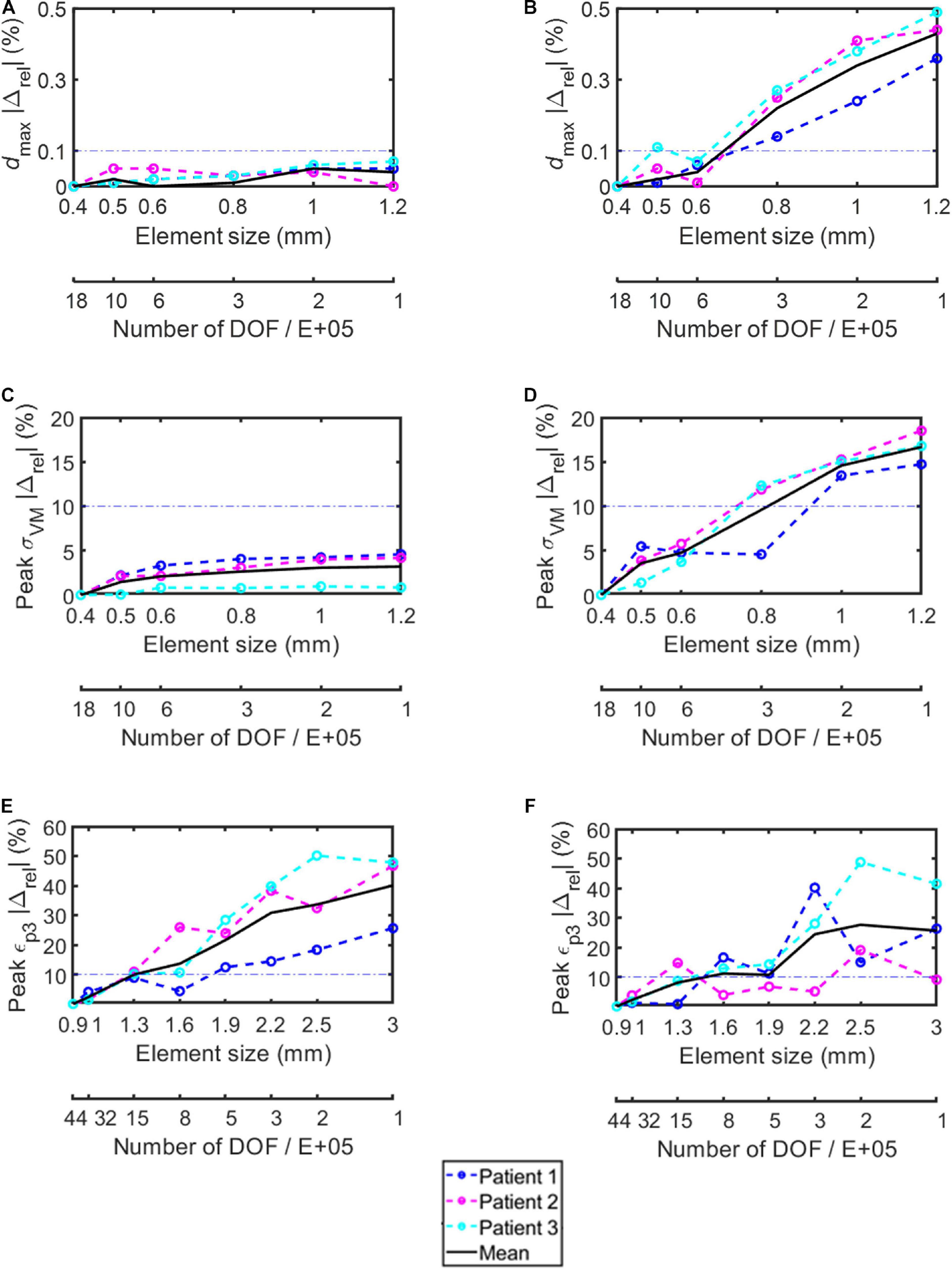
Figure 3. Percentage absolute difference with respect to the finer mesh in the simplified screws (A,C,E) and in the realistic screws (B,D,F) for maximum total deflection (A,B), peak von Mises stress in the screw (C,D), and peak minimum principal strain in the bone (E,F). Dashed lines represent results for each subject, continuous black lines represent averaged values, dash-dotted lines represent the chosen 10% difference chosen as threshold.
The percentage absolute change with respect to the finer mesh in peak σVM was higher for the realistic screw compared to the simplified one (Figures 3C,D). In particular, while for the simplified model a percentage relative difference lower than 5% was observed for each tested element size, for the realistic case an element size of 0.6 mm allowed to achieve relative differences of approximately 5% or below. The σVM distribution in the screws were similar for the models with different element size for both simplified and realistic screw geometry (Figure 4).
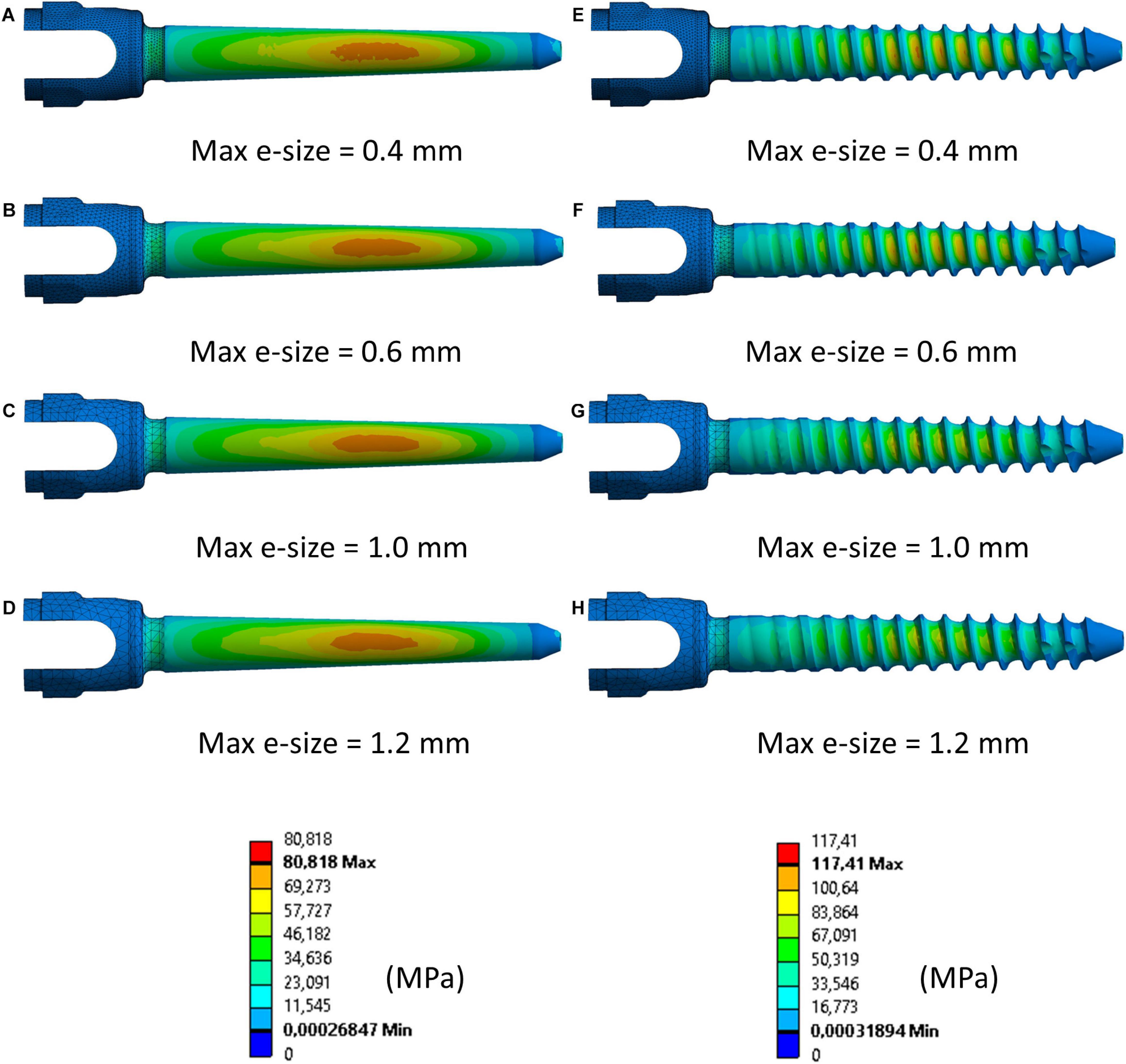
Figure 4. Distribution of von Mises stress in simplified (A–D) and realistic (E–H) left screws (Patient #2) for four different element sizes. Compressed fibers side (caudal view). The mesh was hidden in the main body of the screw to better visualize the stress distribution.
The peak εp3 values occurred at the interface between the bone and the left screw for Patient #1 and #2, and at the interface between the bone and the right screw for Patient #3 (Figure 5). The absolute percentage relative differences in peak εp3 were much higher than for the peak σVM. For both simplified and realistic models, element size of 1 mm in the bone led to absolute percentage relative difference of approximately 5% or below for the three patients (Figures 3E,F).
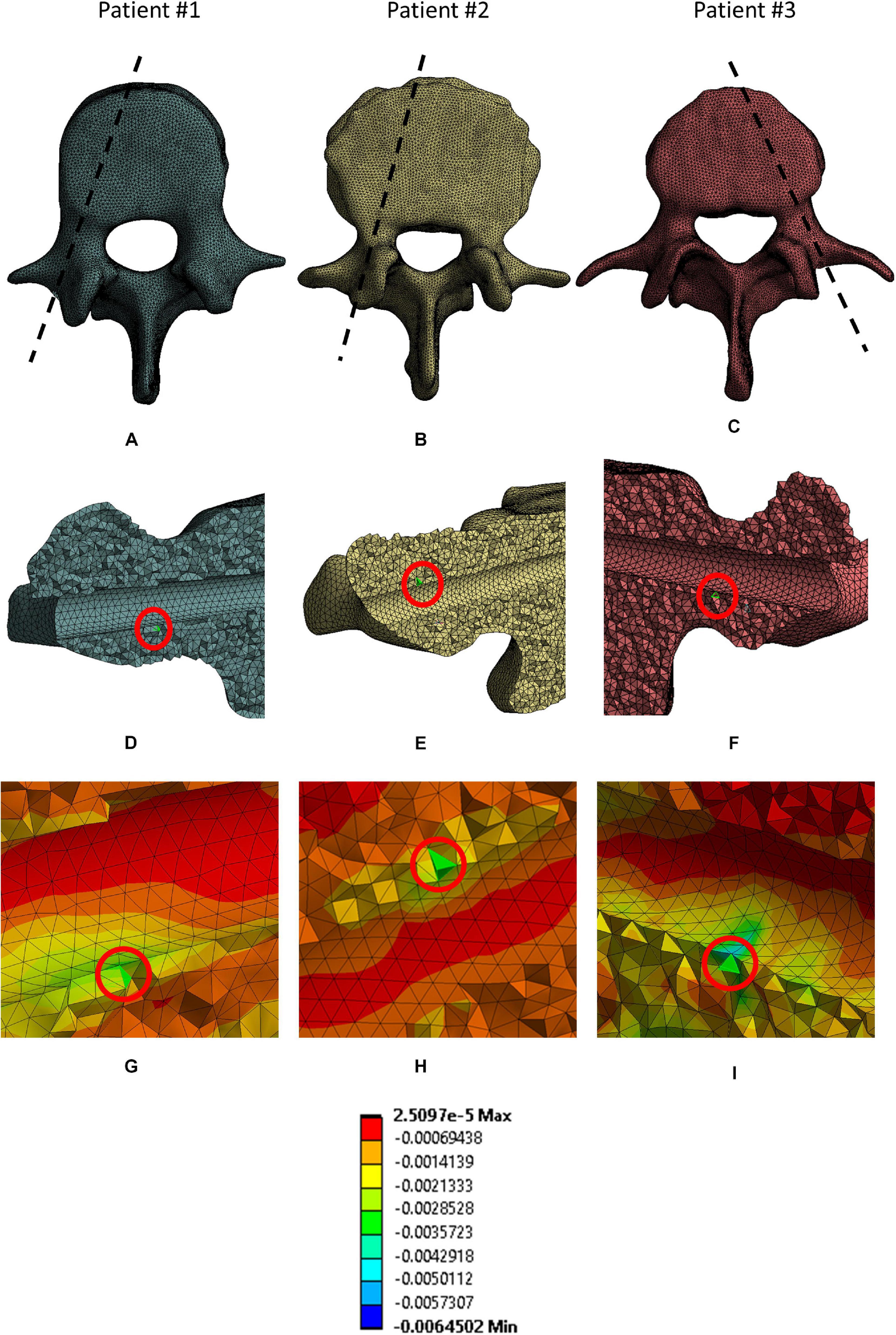
Figure 5. Location of elements where peak εp3 in the bone were. For each patient the following views are reported: the projection of the sagittal section corresponding to the location of the elements in a cranial view (A–C); the location of the peak (red circle) in a sagittal section for each patient (D–F); a magnified view of the mesh in the area corresponding to the selected peaks (G–I).
For the following analyses, an element size of 0.4 mm was chosen in the screws because the computational time was not significantly affected (Tables 2, 3), and an element size of 1.0 mm was chosen in the bone.
Effect of Size and Geometry of the Screw
The screw’s diameter had a more significant influence on dmax than the screw’s length in both simplified and realistic models, for both left and right screws (Table 4). Changes in length resulted in median values of percentage changes in dmax between 4 and 10%; whilst, changes in diameter resulted in median values of percentage changes in dmax between 28 and 36%. Similar changes were observed between right and left screws, for both simplified and realistic cases, and between simplified and realistic models, for both left and right screws. Very similar trends were found for the three patients. As expected, for a fixed length, the dmax increased for lower diameters; for a fixed diameter, the dmax decreased for longer screws.
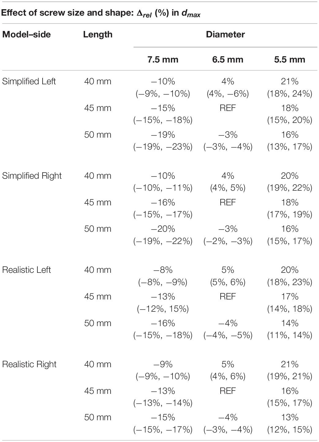
Table 4. Percentage difference in maximum total deflection of the head of the screw, for simplified and realistic models, reported as median value and minimum and maximum values with respect to the nominal condition (D = 6.5 mm and L = 45 mm) over the three patients.
The diameter had higher impact on peak σVM than the length for both simplified and realistic models (Table 5). In fact, changes in length resulted in median values of percentage changes in peak σVM between 1 and 6%; instead, changes in diameter resulted in median values of percentage changes in peak σVM between 6 and 27%. For both simplified and realistic models, similar percentage differences and trends were found between right and left screws. However, an asymmetry was found for Patient #1 in the models with realistic screws with D = 5.5 mm: for the three values of L, percentage differences in peak σVM between 2 and 11% (left screws) and between 25 and 29% (right screws) were found. Since this patient had the largest pedicle among patients, models with screws with D = 5.5 mm were more sensitive to local changes in material properties. Generally, lower percentage differences in peak stress were found for the realistic screws compared to those obtained from simplified models. The percentage differences presented overall similar trends for the three patients. Also, the peak σVM in the screw was higher in realistic models compared to those with simplified screws. For a fixed length, the σVM increased for lower diameters; for a fixed diameter, the σVM decreased for longer screws. However, in some cases with realistic screws, this behavior was not observed probably due to differences in local mechanical properties of bone adjacent to screws among models with different screw sizes.
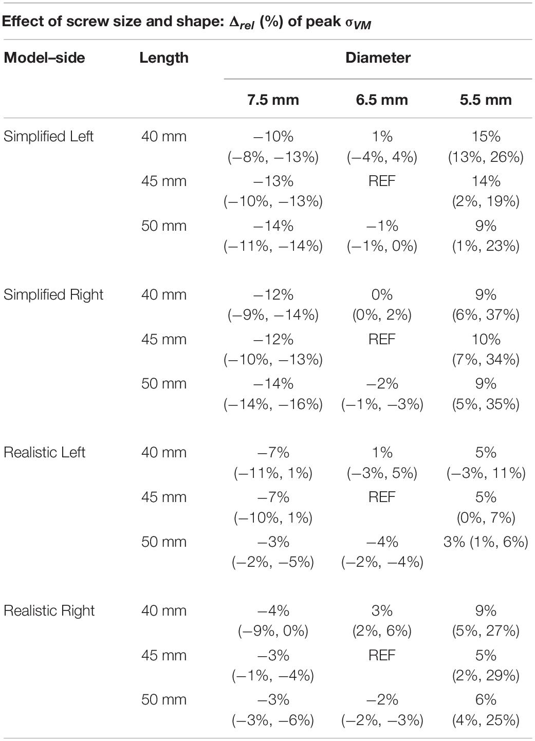
Table 5. Percentage difference in peak Von Mises stress in the screws, for simplified and realistic models, reported with respect to the nominal condition (D = 6.5 mm and L = 45 mm) as median value and minimum and maximum values over the three patients.
For both simplified and realistic models, the diameter affected the mean εp3 more than the length (Table 6 and Figure 5). In fact, changes in diameter resulted in median values of percentage changes in mean εp3 between 30 and 47%, while changes in length resulted in median values of percentage changes in mean εp3 between 10 and 22%. For both simplified and realistic models, similar percentage differences and trends were found between right and left screws. Generally, similar percentage differences in mean εp3 were found for the models with realistic or simplified screws. Also, the mean εp3 in simplified models were similar to those with realistic screws. The percentage differences presented overall similar trends for the three patients. For a fixed length, the mean εp3 increased for lower diameters; for a fixed diameter, the mean εp3 decreased for longer screws.
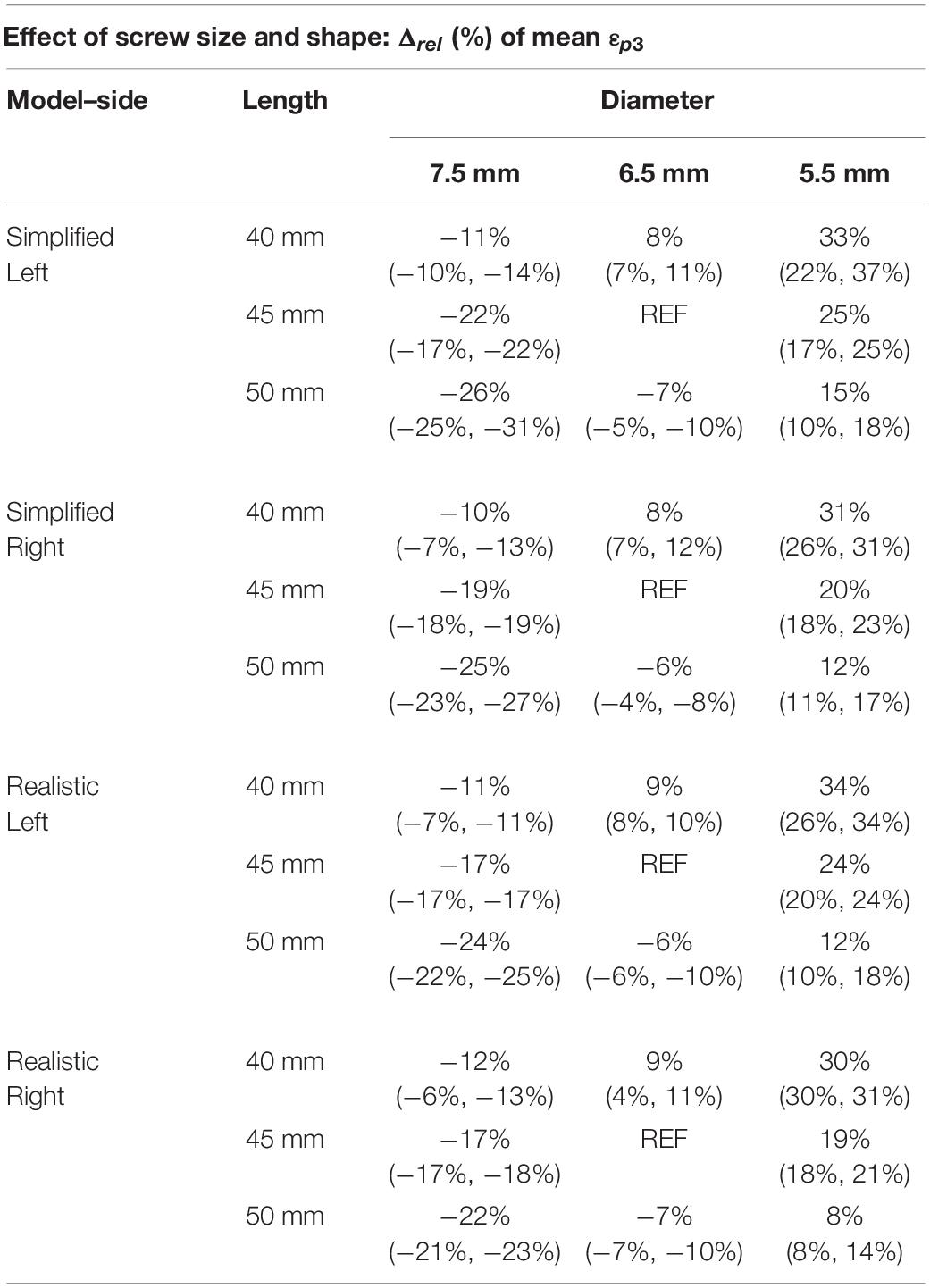
Table 6. Percentage difference in mean Minimum principal strain in a ROI at the screw-vertebra interface, for simplified and realistic models, reported with respect to the nominal condition (D = 6.5 mm and L = 45 mm) as median value and minimum and maximum values over the three patients.
Comparison Between Simplified and Realistic Screw Geometry
If data were pooled for the different patients, sizes and sides, the dmax calculated for models with realistic or simplified screws correlated very well (R2 = 0.99; Slope = 0.918, Intercept = 0.026 mm) (Figure 6A). A good correlation was also found between the peak σVM calculated from the realistic and simplified models (R2 = 0.82) (Figure 6B). Nevertheless, the simplified models systematically underestimated the peak stress compared to the realistic ones (Slope = 1.2, Intercept ∼ 17 MPa).
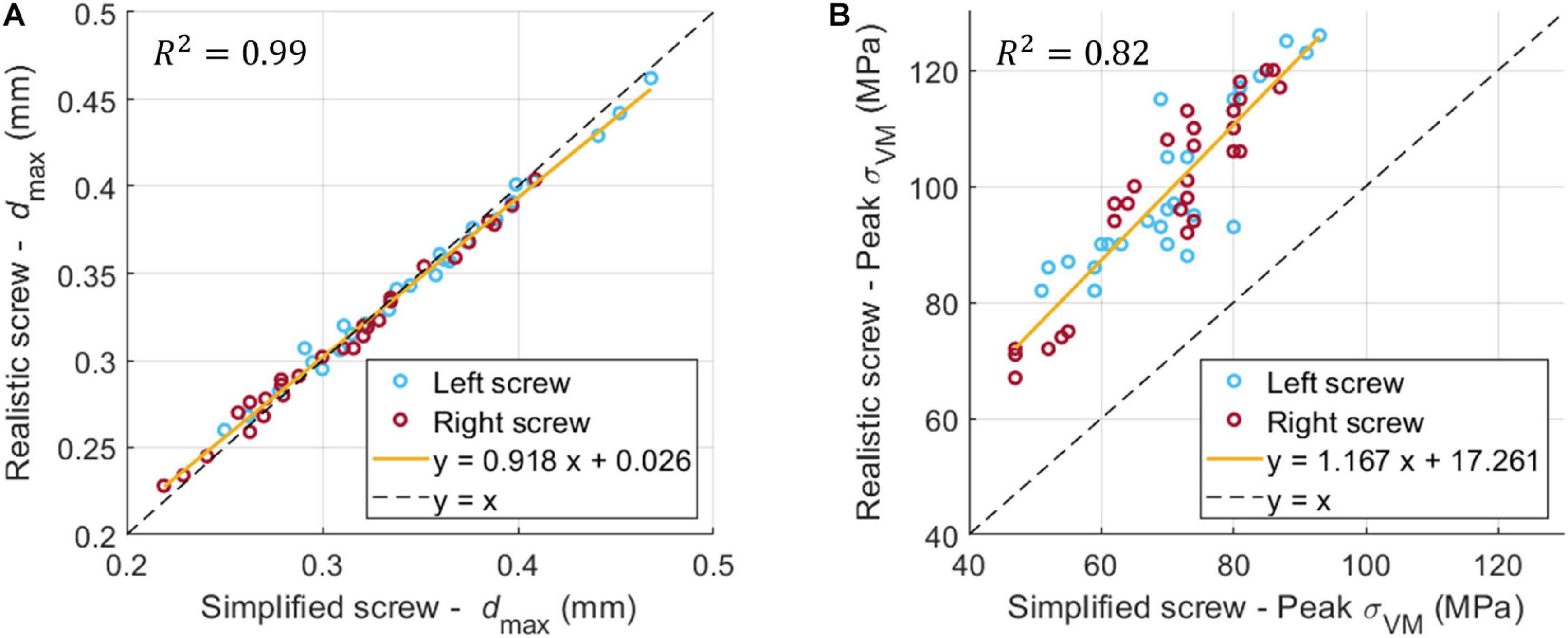
Figure 6. Linear correlation between dmax (A) and σVM (B) for the realistic and simplified models (data pooled for the three patients, two sides, nine sizes).
The peak εp3 was highly influenced by the combination of screw geometry (simplified vs. realistic) and the distribution of Young’s modulus in the bone, whereas the distribution of values of εp3 within a ROI around the screw was similar for simplified and realistic design of screws, with only a localized increase of strain for a few elements in the realistic screw models (Figure 7).
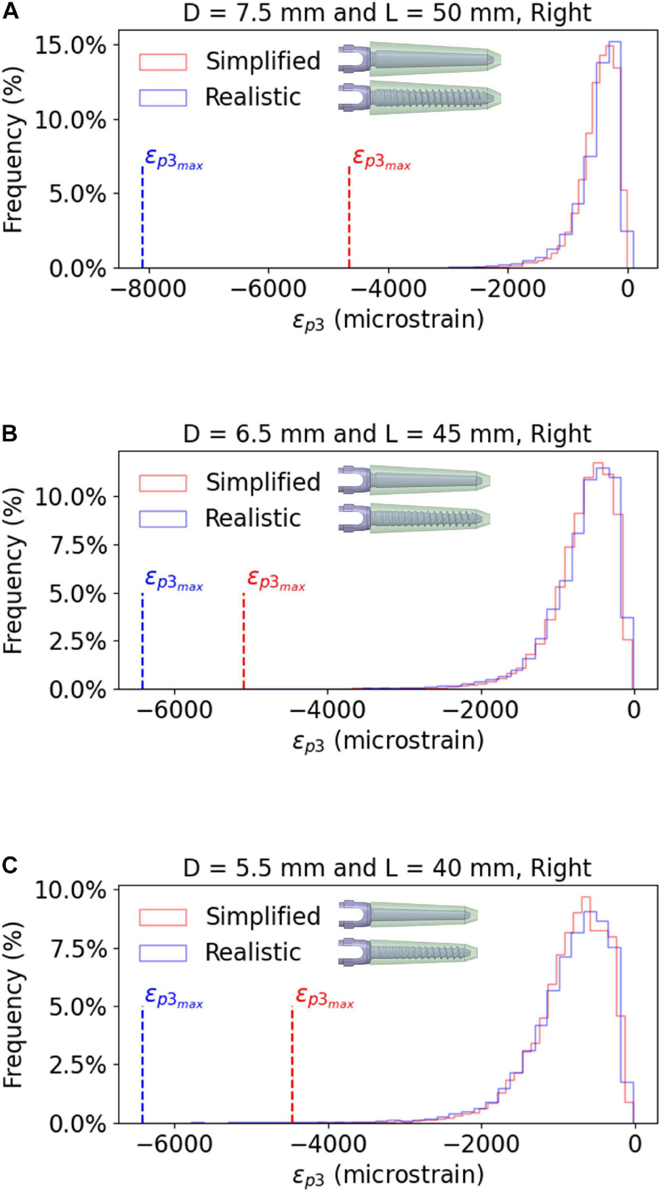
Figure 7. Frequency plots for the values of εp3 within a bone ROI around the right screw, for realistic and simplified models. The data are reported for the largest screw size (A), the optimal screw size (B) and the smallest screw size (C), evaluated for Patient #2. Similar trends were observed for the other patients and the left screws.
Discussion
This study aimed to generate and verify a subject-specific CT-based FE model of the human vertebra implanted with two pedicle screws. The model was then used to evaluate the effect of the size and geometry of the pedicle screws on the mechanical properties of the screws-vertebra structure.
Element sizes of 0.6 mm in the screw and 1.0 mm in the bone were associated to a relative difference of approximately 5% for both simplified and realistic models. Similarly, Costa et al. (2019) reported that element size of 1 mm was required for CT-based subject specific heterogeneous FE models of healthy non-instrumented vertebrae loaded in compression. Widmer et al. (2020) reported the results from a validation study for CT-based subject specific heterogeneous animal (bovine and porcine) vertebrae with realistic pedicle screws. They opted for smaller element sizes at the level of the screw cavity compared to the bone farer from the implant resulting in about 230,000 tetrahedral elements in the bone and 10,000 shell elements in the screw; however, no mesh refinement study was reported. Bianco et al. (2019) compared the fixation strength of realistic pedicle screws with different dimensions, bone engagement and entry point preparation under axial and non-axial forces, and chose an element size in the bone of approximately 0.3 mm around the screw thread and 1 mm in regions farer from the implant obtaining differences in results under 8% with respect to the finest mesh. It should be noted that little details are usually reported in the literature about the choice of the mesh size in models to simulate the biomechanics of vertebrae implanted with pedicle screws. This is critical as “verification” is one of the important steps to give credibility to the models for the assessment of the efficacy of medical devices (ASME, 2020).
As expected, in this study percentage relative differences in peak σVM were higher in the realistic screws compared to the simplified ones. In fact, for the realistic screws different element sizes result in a more or a less accurate discretization of the thread features, which is not modeled in the simplified screw. It should be noted that the presence of the thread resulted in a 22–29% higher peak σVM in realistic models compared to simplified ones for the baseline configuration (D = 6.5 mm, L = 45 mm). This was due to the fact that areas of concentration of stress occurred close to the thread, which may play a larger role compared to the diameter of the screw. However, the σVM distribution over the screws was similar among the different mesh sizes for both realistic and simplified models, showing that the stress pattern is not much influenced by the element size.
The diameter of the screw had higher impact on the maximum displacement, on the peak σVM in the screws and on the mean εp3 in the bone than the length of the screw. This shows that for mono-cortical screws the anchorage in the pedicle, which mainly consists of cortical bone, is more important compared to the anchorage within the vertebral body, which is mainly composed of trabecular bone. Therefore, finding the compromise between the largest diameter of the screws by avoiding iatrogenic fractures is crucial to provide a good anchorage on the cortical bone, which results in lower micromotions at the screw-vertebra interface and better distribution of stress, thus preventing post-operative complications. Our results are in line with most experimental and numerical studies in the literature, that showed the predominant effect of the diameter of the screws compared to their length (Zindrick et al., 1986; Chen et al., 2003; Cho et al., 2010; Matsukawa et al., 2016, 2020; Bianco et al., 2019; Biswas et al., 2019). Matsukawa et al. (2016) evaluated the effect of different screw sizes on fixation with a cortical bone trajectory, where screws are inserted pointing laterally in the transverse plane during superior screw angulation in the sagittal plane, and anchor only on cortical bone in the pedicle without the contribution of trabecular bone in the vertebral body (Santoni et al., 2009), by using an FE model including bone heterogeneities and realistic screw design. They found that some mechanical properties of the vertebra-screws construct were not significantly affected by increasing the diameter of screws. Even if our results for the impact of the diameter of the realistic screw seem to disagree with those by Matsukawa et al. (2016), this should be taken with caution as these differences may be due to different modeling techniques and different mechanical metrics used to evaluate the effect of the size of the screw. Matsukawa et al. (2020) investigated the effect of screw size on fixation in osteoporotic vertebrae by FE analysis. Their results showed that by increasing the diameter and the length of screws, the pullout strength and vertebral fixation strength increased; they also showed that the screw diameter had a more important effect than screw length on the vertebral fixation strength, similarly to the results of the present study. However, the modeling approach and boundary conditions of the two studies are substantially different so both outcomes are complementary.
Overall, the predictions of the simplified models correlated well with the predictions from the realistic ones, especially for the global structural properties (dmax). This finding suggests that geometrical differences between the two designs of screws and local differences of material properties around the screw between the two models do not influence the overall stiffness of the model. Inzana et al. (2016) modeled a homogeneous cylindrical block of trabecular or cortical bone and compared a simplified cylindrical screw with a bonded interface and a realistic threaded screw with frictional contact with a pseudo-threaded screw with calibrated contact conditions. They found that the simplified model underestimated (70% difference, averaged value extracted from Figure 4 in that study) the displacement of the screw head with respect to the realistic case. They have also reported a similar overestimation of the global stiffness from the analysis of a model for the fixation of a proximal humerus fracture. In this study, it was found that the maximum deflection of the screw head was slightly higher in the simplified case, but a bonded interface was considered for both simplified and realistic models. The different results could be due to differences in material models, interfaces, geometries and applications between the two studies. Moreover, in this study the simplified models underestimated the peak σVM, due to the lack of stress raisers considered in the realistic design. These differences could also be amplified by local heterogeneity in the Elastic modulus of bone elements. In fact, the distribution of Young’s modulus in the bone had a strong influence on the peak εp3, whereas the distribution of strain around the screw-bone interface was similar for simplified and realistic models. This finding highlights the importance of the choice of modeling the screw’s geometry realistically or to use a simplified model depending on the application.
There are some limitations in this study. First, it is important to note that before this computational model can be used in the clinical setting, additional to the verification and sensitivity analysis of the model, a direct validation of this approach should be made with respect to measurements from ex vivo experiments. This study is the first step in the identification of the best approach to optimize the virtual assessment of pedicle fixation by accounting for realistic vertebral geometry and density distributions and by modeling the screw with a realistic or simplified geometry. Validation of the model against advanced time-lapsed mechanical testing, micro-CT imaging and digital volume correlation approaches (Dall’Ara et al., 2017) to measure the strain distribution in the bone tissue will follow in future studies. The screw-bone interface was modeled as perfect bonding. While this choice may lead to less realistic stress and strain patterns in the screw and in the bone, it simplifies the comparison between the models with realistic and simplified screws. Moreover, only the most inferior vertebra of a short-segment pedicle screw construct was modeled, excluding from the analysis the other features of the implanted spine unit. This choice was considered acceptable for this study that focused on vertical loads perpendicular to the axis of the screws. Nevertheless, in order to evaluate the effect of the screw size in physiological conditions, more complex geometry should be modeled. The insertion points of pedicle screws, as well as the orientation of the screw axes in the sagittal and transverse planes are important factors that influence the stress distribution on the screws and the bone. These two parameters should be considered in future parametric studies.
Finally, the effect of the size of the screw has been evaluated with nine discrete configurations instead of analyzing the possible range of parameters continuously with statistical methods. While this choice was driven by the configurations of screw size available in the market, a more general approach could have highlighted optimal combinations of diameter and length for the specific patients. In fact, the simplified design of the screw would allow to implement more easily a parametric model, and mesh morphing techniques could be applied to update the nodal positions to accommodate shape variations (Biancolini, 2017). This approach combined with reduced order modeling techniques could be used to accelerate the workflow and test several combinations of geometrical properties of the screw for a population of patients and to expand to non-linear analyses.
In conclusion, this study highlights the influence of size and geometry of screws on the biomechanics of a vertebra with two pedicle screws. In particular, the diameter of the screw should be optimized for each patient as it has a large impact on the stress in the screw. Moreover, modeling the screw with simplified geometry systematically underestimate the peak stress and should therefore be accounted for when interpreting the results from the FE analyses.
Data Availability Statement
The raw data supporting the conclusions of this article will be made available by the authors by contacting the corresponding author. Results and example of the models are available at: https://bit.ly/37JflPc.
Author Contributions
MS, TV, MR, and ED: research design. TV, CS, and TG: acquisition of data. MS and ED: analysis and interpretation of data. All authors drafted the manuscript and revised it critically, reviewed and agreed upon the final version of the manuscript.
Funding
This project was partially funded by the European Union’s Horizon 2020 Research and Innovation Programme under the Marie Skłodowska-Curie grant agreement Spinner No. 766012, and by the Engineering and Physical Sciences Research Council (EPSRC) Frontier Multisim Grant (EP/K03877X/1 and EP/S032940/1).
Conflict of Interest
MS and MR were employed by company Ansys (France). CS and TG were employed by company Aesculap (Germany).
The remaining authors declare that the research was conducted in the absence of any commercial or financial relationships that could be construed as a potential conflict of interest.
Acknowledgments
We gratefully acknowledge Dr. Abdollah Yassine Moufid for the help with the acquisition of data.
References
Abbeele, M. V., den Valiadis, J.-M., Lima, L. V. P. C., Khalifé, P., Rouch, P., and Skalli, W. (2018). Contribution to FE modeling for intraoperative pedicle screw strength prediction. Comput. Methods Biomech. Biomed. Eng. 21, 13–21. doi: 10.1080/10255842.2017.1414200
ASME (2020). Assessing Credibility of Computational Modeling through Verification and Validation: Application to Medical Devices – ASME. Available online at: https://www.asme.org/codes-standards/find-codes-standards/v-v-40-assessing-credibility-computational-modeling-verification-validation-application-medical-devices (accessed October 26, 2020).
Bianco, R.-J., Arnoux, P.-J., Mac-Thiong, J.-M., and Aubin, C.-E. (2019). Thoracic pedicle screw fixation under axial and perpendicular loadings: a comprehensive numerical analysis. Clin. Biomech. 68, 190–196. doi: 10.1016/j.clinbiomech.2019.06.010
Bianco, R.-J., Arnoux, P.-J., Wagnac, E., Mac-Thiong, J.-M., and Aubin, C. -É (2017). Minimizing pedicle screw pullout risks: a detailed biomechanical analysis of screw design and placement. Clin. Spine Surg. 30, E226–E232. doi: 10.1097/BSD.0000000000000151
Biancolini, M. E. (2017). “RBF mesh morphing,” in Fast Radial Basis Functions for Engineering Applications, ed. M. E. Biancolini (Cham: Springer International Publishing), 93–117. doi: 10.1007/978-3-319-75011-8_6
Biswas, J. K., Sahu, T. P., Rana, M., Roy, S., Karmakar, S. K., Majumder, S., et al. (2019). Design factors of lumbar pedicle screws under bending load: a finite element analysis. Biocybern. Biomed. Eng. 39, 52–62. doi: 10.1016/j.bbe.2018.10.003
Bredow, J., Boese, C. K., Werner, C. M. L., Siewe, J., Löhrer, L., Zarghooni, K., et al. (2016). Predictive validity of preoperative CT scans and the risk of pedicle screw loosening in spinal surgery. Arch. Orthop. Trauma Surg. 136, 1063–1067. doi: 10.1007/s00402-016-2487-8
Campbell, J. Q., and Petrella, A. J. (2016). Automated finite element modeling of the lumbar spine: using a statistical shape model to generate a virtual population of models. J. Biomech. 49, 2593–2599. doi: 10.1016/j.jbiomech.2016.05.013
Chen, S.-I., Lin, R.-M., and Chang, C.-H. (2003). Biomechanical investigation of pedicle screw–vertebrae complex: a finite element approach using bonded and contact interface conditions. Med. Eng. Phys. 25, 275–282. doi: 10.1016/S1350-4533(02)00219-9
Chevalier, Y., Matsuura, M., Krüger, S., Fleege, C., Rickert, M., Rauschmann, M., et al. (2018). Micro-CT and micro-FE analysis of pedicle screw fixation under different loading conditions. J. Biomech. 70, 204–211. doi: 10.1016/j.jbiomech.2017.12.023
Cho, W., Cho, S. K., and Wu, C. (2010). The biomechanics of pedicle screw-based instrumentation. J. Bone Joint Surg. Br. 92, 1061–1065. doi: 10.1302/0301-620X.92B8.24237
Costa, M. C., Eltes, P., Lazary, A., Varga, P. P., Viceconti, M., and Dall’Ara, E. (2019). Biomechanical assessment of vertebrae with lytic metastases with subject-specific finite element models. J. Mech. Behav. Biomed. Mater. 98, 268–290. doi: 10.1016/j.jmbbm.2019.06.027
Dall’Ara, E., Peña-Fernández, M., Palanca, M., Giorgi, M., Cristofolini, L., and Tozzi, G. (2017). Precision of digital volume correlation approaches for strain analysis in bone imaged with micro-computed tomography at different dimensional levels. Front. Mater. 4:31. doi: 10.3389/fmats.2017.00031
Elmasry, S., Asfour, S., and Travascio, F. (2017). Effectiveness of pedicle screw inclusion at the fracture level in short-segment fixation constructs for the treatment of thoracolumbar burst fractures: a computational biomechanics analysis. Comput. Methods Biomech. Biomed. Engin. 20, 1412–1420. doi: 10.1080/10255842.2017.1366995
Fedorov, A., Beichel, R., Kalpathy-Cramer, J., Finet, J., Fillion-Robin, J.-C., Pujol, S., et al. (2012). 3D Slicer as an image computing platform for the Quantitative Imaging Network. Magn. Reson. Imaging 30, 1323–1341. doi: 10.1016/j.mri.2012.05.001
Fior Markets (2020). Global Pedicle Screw System Market by Product, Surgery Type, Indication, Application, Region, Industry Analysis, Size, Share, Growth, Trends, and Forecast 2018 to 2025 – Fior Markets. Available online at: https://www.fiormarkets.com/report/global-pedicle-screw-system-market-by-product-polyaxial-375967.html (accessed October 26, 2020).
Gertzbein, S. D., and Robbins, S. E. (1990). Accuracy of pedicular screw placement in vivo. Spine 15, 11–14.
Li, C., Zhou, Y., Wang, H., Liu, J., and Xiang, L. (2014). Treatment of unstable thoracolumbar fractures through short segment pedicle screw fixation techniques using pedicle fixation at the level of the fracture: a finite element analysis. PLoS One 9:e99156. doi: 10.1371/journal.pone.0099156
Matsukawa, K., Yato, Y., and Imabayashi, H. (2020). Impact of screw diameter and length on pedicle screw fixation strength in osteoporotic vertebrae: a finite element analysis. Asian Spine J. doi: 10.31616/asj.2020.0353 [Epub ahead of print].
Matsukawa, K., Yato, Y., Imabayashi, H., Hosogane, N., Abe, Y., Asazuma, T., et al. (2016). Biomechanical evaluation of fixation strength among different sizes of pedicle screws using the cortical bone trajectory: what is the ideal screw size for optimal fixation? Acta Neurochir. (Wien) 158, 465–471. doi: 10.1007/s00701-016-2705-8
Molinari, L., Falcinelli, C., Gizzi, A., and Di Martino, A. (2021). Effect of pedicle screw angles on the fracture risk of the human vertebra: a patient-specific computational model. J. Mech. Behav. Biomed. Mater. 116:104359. doi: 10.1016/j.jmbbm.2021.104359
Morgan, E. F., Bayraktar, H. H., and Keaveny, T. M. (2003). Trabecular bone modulus–density relationships depend on anatomic site. J. Biomech. 36, 897–904. doi: 10.1016/S0021-9290(03)00071-X
Newcomb, A. G. U. S., Baek, S., Kelly, B. P., and Crawford, N. R. (2017). Effect of screw position on load transfer in lumbar pedicle screws: a non-idealized finite element analysis. Comput. Methods Biomech. Biomed. Engin. 20, 182–192. doi: 10.1080/10255842.2016.1209187
Niinomi, M., and Boehlert, C. J. (2015). “Titanium alloys for biomedical applications,” in Advances in Metallic Biomaterials: Tissues, Materials and Biological Reactions. Springer Series in Biomaterials Science and Engineering, eds M. Niinomi, T. Narushima, and M. Nakai (Berlin: Springer), 179–213. doi: 10.1007/978-3-662-46836-4_8
Prud’homme, M., Barrios, C., Rouch, P., Charles, Y. P., Steib, J.-P., and Skalli, W. (2015). Clinical outcomes and complications after pedicle-anchored dynamic or hybrid lumbar Spine stabilization: a systematic literature review. J. Spinal Disord. Tech. 28, E439–E448. doi: 10.1097/BSD.0000000000000092
Qi, W., Yan, Y., Zhang, Y., Lei, W., Wang, P., and Hou, J. (2011). Study of stress distribution in pedicle screws along a continuum of diameters: a three−dimensional finite element analysis. Orthop. Surg. 3, 57–63. doi: 10.1111/j.1757-7861.2010.00112.x
Rajaee, S. S., Bae, H. W., Kanim, L. E. A., and Delamarter, R. B. (2012). Spinal fusion in the United States: analysis of trends from 1998 to 2008. Spine 37, 67–76. doi: 10.1097/BRS.0b013e31820cccfb
Rohlmann, A., Bergmann, G., and Graichen, F. (1997). Loads on an internal spinal fixation device during walking. J. Biomech. 30, 41–47. doi: 10.1016/S0021-9290(96)00103-0
Santoni, B. G., Hynes, R. A., McGilvray, K. C., Rodriguez-Canessa, G., Lyons, A. S., Henson, M. A. W., et al. (2009). Cortical bone trajectory for lumbar pedicle screws. Spine J. 9, 366–373. doi: 10.1016/j.spinee.2008.07.008
Schileo, E., Dall’Ara, E., Taddei, F., Malandrino, A., Schotkamp, T., Baleani, M., et al. (2008). An accurate estimation of bone density improves the accuracy of subject-specific finite element models. J. Biomech. 41, 2483–2491. doi: 10.1016/j.jbiomech.2008.05.017
Su, Y., Wang, X., Ren, D., Liu, Y., Liu, S., and Wang, P. (2018). A finite element study on posterior short segment fixation combined with unilateral fixation using pedicle screws for stable thoracolumbar fracture. Medicine (Baltimore) 97:e12046. doi: 10.1097/MD.0000000000012046
Taddei, F., Schileo, E., Helgason, B., Cristofolini, L., and Viceconti, M. (2007). The material mapping strategy influences the accuracy of CT-based finite element models of bones: an evaluation against experimental measurements. Med. Eng. Phys. 29, 973–979. doi: 10.1016/j.medengphy.2006.10.014
Verma, K., Boniello, A., and Rihn, J. (2016). Emerging techniques for posterior fixation of the lumbar Spine. J. Am. Acad. Orthop. Surg. 24, 357–364. doi: 10.5435/JAAOS-D-14-00378
Wang, W., Pei, B., Pei, Y., Shi, Z., Kong, C., Wu, X., et al. (2019). Biomechanical effects of posterior pedicle fixation techniques on the adjacent segment for the treatment of thoracolumbar burst fractures: a biomechanical analysis. Comput. Methods Biomech. Biomed. Engin. 22, 1083–1092. doi: 10.1080/10255842.2019.1631286
Widmer, J., Fasser, M.-R., Croci, E., Spirig, J., Snedeker, J. G., and Farshad, M. (2020). Individualized prediction of pedicle screw fixation strength with a finite element model. Comput. Methods Biomech. Biomed. Engin. 23, 155–167. doi: 10.1080/10255842.2019.1709173
Wirtz, D. C., Schiffers, N., Pandorf, T., Radermacher, K., Weichert, D., and Forst, R. (2000). Critical evaluation of known bone material properties to realize anisotropic FE-simulation of the proximal femur. J. Biomech. 33, 1325–1330. doi: 10.1016/S0021-9290(00)00069-5
Keywords: spine, spinal fractures, posterior fixation, finite element, sensitivity analysis
Citation: Sensale M, Vendeuvre T, Schilling C, Grupp T, Rochette M and Dall’Ara E (2021) Patient-Specific Finite Element Models of Posterior Pedicle Screw Fixation: Effect of Screw’s Size and Geometry. Front. Bioeng. Biotechnol. 9:643154. doi: 10.3389/fbioe.2021.643154
Received: 17 December 2020; Accepted: 18 February 2021;
Published: 10 March 2021.
Edited by:
Alexandros E. Tsouknidas, University of Western Macedonia, GreeceReviewed by:
Maria Angeles Perez Anson, University of Zaragoza, SpainWenfei Ni, Second Affiliated Hospital and Yuying Children’s Hospital of Wenzhou Medical University, China
Copyright © 2021 Sensale, Vendeuvre, Schilling, Grupp, Rochette and Dall’Ara. This is an open-access article distributed under the terms of the Creative Commons Attribution License (CC BY). The use, distribution or reproduction in other forums is permitted, provided the original author(s) and the copyright owner(s) are credited and that the original publication in this journal is cited, in accordance with accepted academic practice. No use, distribution or reproduction is permitted which does not comply with these terms.
*Correspondence: Enrico Dall’Ara, e.dallara@sheffield.ac.uk