A photoacoustics-enhanced drilling probe for radiation-free pedicle screw implantation in spinal surgery
- 1Department of Electronic Engineering, The Chinese University of Hong Kong, Hong Kong SAR, China
- 2Department of Electronic and Electrical Engineering, Southern University of Science and Technology, Shenzhen, China
- 3School of Science, Nanjing University of Science and Technology, Nanjing, China
This article proposes a novel intra-operative navigation and sensing system that optimizes the functional accuracy of spinal pedicle screw implantation. It does so by incorporating radiation-free and multi-scale macroscopic 3D ultrasound (US) imaging and local tissue-awareness from in situ photoacoustic (PA) sensing at a clinically relevant mesoscopic scale. More specifically, 3D US imaging is employed for online status updates of spinal segment posture to determine the appropriate entry point and coarse drilling path once non-negligible or relative patient motion occurs between inter-vertebral segments in the intra-operative phase. Furthermore, a sophisticated sensor-enhanced drilling probe has been developed to facilitate fine-grained local navigation that integrates a PA endoscopic imaging component for in situ tissue sensing. The PA signals from a sideways direction to differentiate cancellous bone from harder cortical bone, or to indicate weakened osteoporotic bone within the vertebrae. In so doing it prevents cortical breaches, strengthens implant stability, and mitigates iatrogenic injuries of the neighboring artery and nerves. To optimize this PA-enhanced endoscopic probe design, the light absorption spectrum of cortical bone and cancellous bone are measured in vitro, and the associated PA signals are characterized. Ultimately, a pilot study is performed on an ex vivo bovine spine to validate our developed multi-scale navigation and sensing system. The experimental results demonstrate the clinical feasibility, and hence the great potential, for functionally accurate screw implantation in complex spinal stabilization interventions.
Introduction
The population is aging rapidly worldwide. Alongside population aging, the incidence of spinal degenerative pathologies (e.g., herniated discs, narrow lumbar canals) and/or vertebral osteoporotic fractures has been increasing, imposing a high socio-economic burden on eldercare and healthcare systems (Compston et al., 2019; Wang et al., 2020). Once such spine-related diseases occur, the vertebrae may no longer function properly, and, if unattended, become harmful to the surrounding nerves and tissues(Chapman, 2019). It is commonly recognized that spinal fusion surgery, which involves pedicle screw implantation to stabilize the spine, is effective in the recovery of spinal function (Germon and Hobart, 2015). During the procedure, the screws need to pierce the pedicles of the vertebrae and enter the vertebral body. Afterward, the implanted screws are attached to rods that stabilize the affected segments. Such surgery is highly challenging and technically demanding (Maria et al., 2020). First, the pedicle region is so small (around a few millimeters), it is extremely difficult to determine an accurate and safe trajectory for the drilling hole. Since the volume of the pedicle screw is relative to that of the pedicle, the margin of error needs to be within one millimeter to prevent screw misplacement or further cortical wall perforation (Lopera et al., 2010). Moreover, the lack of real-time feedback in the intra-operative phase means the success of pedicle screw implantation largely depends on subjective experience of the surgeon. To summarize, the proximity of vital neural and vascular structures, the added variability of patients, and the region-dependent morphology of the vertebrae, all contribute significantly to the difficulties with accurate screw implantation (Lonstein et al., 1999; Yamada et al., 2022). Several advanced surgical aids have previously been introduced to mitigate the associated complications and to improve accuracy. These are generally divided into two categories: global spatial navigation and local tissue sensing techniques.
The global spatial navigation technique mainly involves computer or robotics-assisted spinal surgery, navigated by macroscopic imaging modalities (Helm et al., 2015; Ahern et al., 2020). Since spinal navigation systems allow for either intra-operative imaging or pre-operative imaging with intra-operative updates, conventional navigation paradigms include intra-operative 2D fluoroscopic navigation (Foley et al., 2001), pre-operative CT with manual intra-operative registration (Nottmeier and Crosby, 2007), pre-operative CT with fluoroscopic registration and update, and intra-operative CT or CBCT (Tian et al., 2011; Dea et al., 2016; Cool et al., 2021; Zhang et al., 2021; Felix et al., 2022; Tabarestani et al., 2022). Common to these solutions is their association with X-ray-like imaging (fluoroscopy or CT-based navigation solutions featuring ionizing radiation), which can harm both patient and surgeon (Hecht et al., 2018; Ahern et al., 2020).
The other category of intelligent surgical aids is associated with local tissue sensing, also referred to as sensor-enhanced surgical instruments, that identify different tissue types and possess an integrated warning component. Intensive studies have been conducted into local tissue sensing instruments for spine-related surgeries. Li et al. (2022) proposed a surgical status perception method using an installed acceleration sensor and force sensor in robot-assisted spine surgery that mimics the surgeon’s tactile sensing. Experiments have proved that the fusion of two tactile signals can significantly improve status recognition accuracy. Electromyography is another option, although not widely adopted due to its lower sensitivity (Duffy et al., 2010). Furthermore, other professionals are required to interpret these signals, for the technology fails to predict an impending cortical bone breach in advance. To date, the only commercially available product, the so-called Pedi-Guard probe instrument, is based on electrical conductivity measurement to indicate proximity to the cortical wall of the vertebra (Ovadia et al., 2011). It can distinguish different tissues by comparing electrical conductivity. However, it lacks directional information about the sensed signals (Bolger et al., 2007). In other words, when the instrument tip is close, but parallel to the cortical wall, the sensing technique issues a warning. Yet even if it correctly detects an impending cortical breach, the surgeon still has no idea in which direction the breach is about to occur, because the electrical conductivity measurement occurs in all directions simultaneously. This means that when the instrument issues a warning, the surgeon must make the next attempt without any directional input.
Endoscopic ultrasound (EUS) also holds the potential for in situ tissue sensing and characterization (Mujagic et al., 2008; Manbachi et al., 2014). However, experimental results have proven unreliable due to the high acoustic impedance to the US from the bone (Aly et al., 2011). For superior image quality and tissue composition imaging characteristics, photoacoustic imaging (PAI) has been introduced as an alternative (Steinberg et al., 2019; Gonzalez et al., 2021). First discovered in 1880 by Bell, the PA effect has developed as an emerging medical imaging modality, and is widely adopted in various fields (Zhou et al., 2014). The principle of PAI is as follows: once the tissue is exposed to pulsed laser beams, it absorbs the energy and converts it into heat. Simultaneously, its temperature increases locally and thermal expansion occurs (Xu and Wang, 2006). Such expansion enables the tissue to emit ultrasonic waves, which are detected by an ultrasound transducer for subsequent image reconstruction and visualization (Kruizinga et al., 2014). PAI combines the merits of both optical and ultrasound imaging, yielding high-quality images with high resolution and contrast (Xu and Wang, 2006). Furthermore, it is radiation-free, and capable of both morphological and functional imaging. It thus holds huge potential for clinical translation (Beard, 2011). According to differences in excitation source and image reconstruction techniques, PAI can be categorized into different types. One of these is photoacoustic tomography (PAT), which exploits an unfocused beam for imaging (Sangha and Goergen, 2016). In general, there are several transducers, and the collected information is transferred to the computer for image reconstruction. Another type is photoacoustic microscopy (PAM), which employs a focused laser and transducer without needing a complex reconstruction algorithm (Yao and Wang, 2013). Unlike PAT, PAM has the advantage of imaging precise tissue samples and cells. The last type is photoacoustic endoscopy (PAE), a modality usually applied in invasive operations, which has a high standard in relation to the size of the probe (Joon-Mo Yang et al., 2009; Guo et al., 2020). In sum, PAI can generate images of high quality across a broad range of applications and holds huge potential in tissue sensing and characterization (Zhao et al., 2019). More recently, Gonzalez et al. (2021)developed a combined US and PAT guidance system aimed at avoiding the pedicle screw misplacement and accidental bone breaches that can lead to nerve damage. Pedicle cannulation was conducted on a human cadaver, with co-registered PAT and US images acquired at various time points during the procedure. However, the US/PAT guidance system only focuses on macroscopic anatomical navigation, without taking fine-grained local tissue characterization into consideration. To the best of our knowledge, local bone tissue sensing inside the vertebrae, based on a PAE-enhanced surgical instrument for guiding pedicle screw implantation, has not previously been studied.
In this article, we propose for the first time, a multi-scale surgical navigation and sensing system for pedicle screw insertion based on radiation-free dual-mode US/PA. More specifically, a macroscopic US imaging system achieves contextual awareness for global guidance of the drilling entry and coarse insertion path, while a mesoscopic PAE-enhanced smart probe instrument offers in situ tissue characterization for fine path optimization of screw insertion. Hence, in combination with US image guidance, such PAE sensing is exploited to monitor and even warn of cortical bone breaches inside the vertebrae, thereby optimizing screw implantation in complex spine-related surgeries.
Materials and methods
Radiation-free, multi-scale navigation and sensing systems for pedicle screw implantation optimization
The overall system configuration of the multi-scale surgical navigation and sensing paradigm, based on radiation-free intra-operative US/PA imaging, is presented in Figure 1:
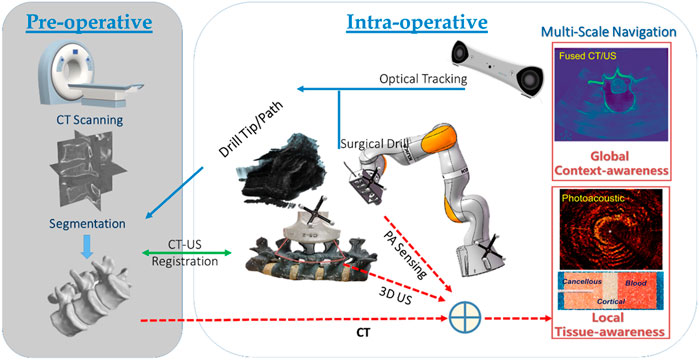
FIGURE 1. Multi-scale surgical navigation and sensing paradigm based on radiation-free intra-operative US/PA imaging.
The combination of global context-awareness via pre-operative CT and intra-operative US, along with local tissue-awareness via in situ PA sensing at a clinically relevant mesoscopic scale can enhance comprehensive perception for complication-free guidance of bone drill and pedicle screws through vertebrae. Specifically, a CT scan is performed and subsequently segmented to produce a 3D model of the bony surface of the spine. Once non-negligible patient movement occurs during the operation, the tracked US probe is scanned to obtain a series of 2D US images, yielding 3D volumetric data of the affected vertebral segments. In the registration phase, US-CT registration is conducted via automatic bony surface detection in US images, followed by Iterative Closest Point (ICP)-based point cloud registration. Afterward, the data on the drill bit, and the updated insertion path—due to any spinal segment posture variation—can be overlaid on a fused CT/US volume. Thus, with the position tracking data of the drill, the multi-scale navigation and sensing system allows for both context-aware global navigation and tissue-aware local sensing in complex spinal surgeries: 1) Context-aware global navigation visualizes the drill bit and insertion path from the fused CT model/US volume of the affected spine in real time. Thereafter, navigation of the drill and screw implantation, associated with an online updated insertion path, is effected based on the posture tracking data and the related US-CT registration result. 2) An embedded PAE probe inside the surgical drill is simultaneously employed for in situ identification of the tissue types aside of the drill bit (e.g., cortical and cancellous bones, and critical vascular/neurological structures) for optimizing fine orientation of the drilling probe in tissue-aware local sensing. Hence, the comprehensive fused perception serves as a multi-scale navigation and sensing paradigm enabling accurate screw implantation in complex spine-stabilization interventions.
Macroscopic 3D ultrasound-guided global contextual navigation
3D US imaging system setup
Prior to spinal surgery, a patient usually receives routine CT scanning for pre-operative examination and diagnosis. Afterward, challenging manipulations, such as pedicle screw implantations, are executed with the assistance of image-based surgical navigation in the intra-operative phase. Relative motion and deformation between the inter-vertebral segments can occur due to interactive force between the drill and the affected vertebrae. Therefore, to achieve on-the-fly status updates during the operation, a 3D US imaging system is established for continuous monitoring of the spinal segment being operated upon. Figure 2A and Figure 3 demonstrate the acquisition, calibration, segmentation, compounding, and visualization of the US volume. Afterward, such reconstructed US volume can be used intra-operatively in conjunction with the spinal bone surface model segmented from the pre-operative CT, together providing a global contextual perception for accurate pedicle screw implantation.

FIGURE 2. (A) Schematic diagram of the intra-operative US navigation system. (B) Schematic diagram of drilling probe. PC: personal computer, NDF: Neutral Density Filter, PD: Photodiode, BS: beam split, OL: object lens, PH: pin hole, CL: collimator, CSL: conductive slip, SMF: single model fiber, BD: bone drill, GC: grin collimator, GL: Grin Lens, AL: aspherical lens, RF: reflector.
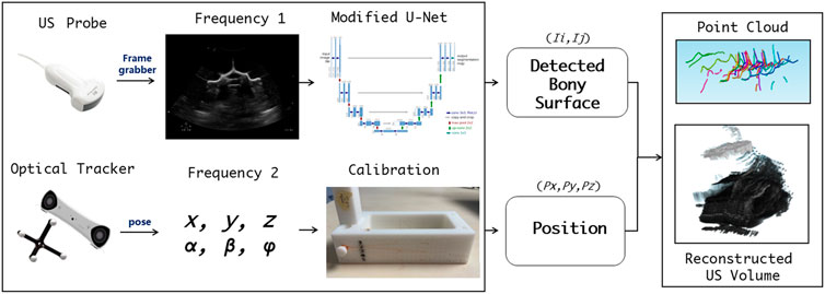
FIGURE 3. Workflow for acquisition, calibration, segmentation, compounding, and visualization of the US volume.
Pre-operative CT registration with intra-operative 3D US
To achieve co-registration between the reconstructed US volume and the bone surface model segmented from CT, two consecutive tasks are performed, i.e., bone surface detection of US images, followed by hierarchical coarse-fine point cloud registration.
Due to the physical nature of spinal sonography for osseous tissue imaging, only bone surface can be visualized on US images, which are highly sparse, thus making it difficult to learn via a conventional U-Net. In this study, we apply the U-Net with several modifications, i.e., employing two loss functions to ensure that the augmented U-Net is well trained (Ibtehaz and Rahman, 2020). The first loss utilizes the distance field of the bone surface as a learned target, where a heatmap-like learned target is generated via Gaussian convolution. As the learning loss reduces, the sigma of the heatmap becomes smaller to enable more accurate bone surface detection. The second loss is to estimate which level of the spine the processed US images belong to, so that the sigma of the aforementioned heatmap can be adjusted (see Figure 4A).
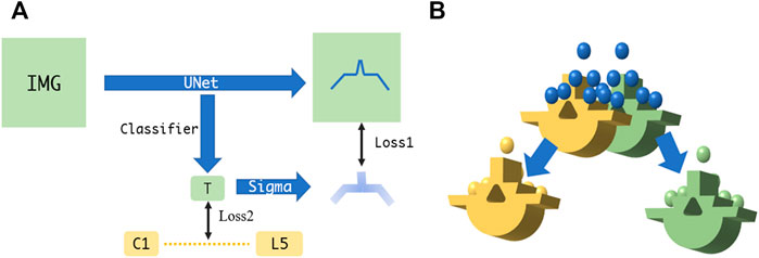
FIGURE 4. (A) Augmented U-Net using two losses for accurate bone surface detection. (B) Fine point cloud registration between US and CT.
The overall point cloud registration is achieved in a hierarchical coarse-to-fine alignment. The coarse registration step extracts the center of the mass, plus the orientation from the bone surface point clouds detected from the US volume, such that both point clouds between the US and the CT possess the same orientation. This step is performed by decomposing both point clouds via principal component analysis (PCA) and aligning their corresponding principal axes accordingly (Jolliffe and Cadima, 2016). The subsequent fine registration step aligns the specified spine level between the CT vertebrae model and the associated US point clouds. Specifically, the US point clouds near the target spine level are automatically selected for ICP registration (Shi et al., 2006). This step selects and removes neighboring points in an iterative manner, where the criterion is to execute registration for a specified spine level based on the point clouds obtained through different radius configurations, and to eventually select the radius with the smaller MSE loss. After several radius selections, the filtered US point clouds are registered to the corresponding CT spine level model (see Figure 4B).
Mesoscopic photoacoustic-enhanced drilling probe for local tissue sensing
Cancellous bone absorption spectrum
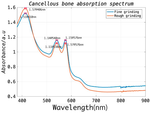
In general, during the procedure, the surgical drill is delivered through the muscle and then reaches the outer border of the cortical bone of the lamina. It subsequently further penetrates the cancellous bone of the vertebra through an appropriate entry point on the cortical bone. As the drill advances into the vertebral body, the associated position of the drill within the vertebra provides critical information feedback for achieving the ultimate functional outcome without post-operative complications (Weiss et al., 2010). Since the pedicle structure of the vertebra is highly restricted (a minimum of approximately 3.5 mm), a safe distance between the drill bit and cortical walls (1.44 mm) must be ensured, requiring accurate differentiation between cortical and cancellous bone (An and Benoit, 1998). To this end, the optical absorption characteristics of cortical and cancellous bone should be investigated to select an appropriate laser wavelength for signal excitation. To this end, the spinal model of a bovine sacrificed less than an hour prior was prepared to expose its cancellous bone, and a tweezer was then used to carefully separate the cancellous bone from the cortical bone. The cancellous bone of approximate 2 g was first utilized for rough grinding and placed in the integrating-sphere of the testing machine. The UV spectrophotometer (UV-2600, Shimadzu [Shanghai] Global Laboratory Consumables Co., Ltd.) can cover the wavelength range of 340–960 nm. Subsequently, the coarsely processed cancellous bone was further subjected to fine grinding. The measuring steps were then repeated. As illustrated in Figure 5, the experimental results demonstrated that the strongest absorption exists at 406 nm and stronger absorption peaks at 540 and 576 nm for the prepared bone samples. Therefore, in this study, we prefer a 532 nm pulse laser as the excitation source, which is well suited for spinal bone tissue characterization due to the overall cost considerations associated with the laser source.
PA signal acquisition and characterization
In this study, we determined an appropriate excitation wavelength as noted in the previous section by analyzing the absorption spectrum of cancellous bone and its cost. With PA imaging, differences of amplitude and frequency between the PA signals on different tissue components have significant impact on the resulting images. It was previously reported that Shubert and Lediju Bell (2018) utilized ex vivo photoexcitation and in vitro reception to qualitatively characterize cortical and cancellous bone based on PAT. However, for the PAE configuration in this study, PA signal characterization for two tissue components (cortical bone vs. cancellous bone) must present a clear distinction. In addition, there is a need to prevent PA signal interference with other tissue components, such as muscle, skin, and blood. To this end, an ex vivo measurement experiment using a single element ultrasonic transducer was designed for PA signal characterization of cortical bone and cancellous bone (see Figure 6).
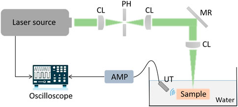
FIGURE 6. Signal acquisition and characterization of cancellous bone and cortical bone based on a single element ultrasonic transducer.
PAE-enhanced drilling probe design
A PAE-enhanced drilling probe was developed for local tissue sensing inside the vertebrae to facilitate fine orientation adjustment for drilling path optimization. Specifically, a cannulated drill was customized for the integration of a PAE probe based on metal 3D printing. Thus, the developed PAE probe was built into a cannulated drill equipped with a mesopore, allowing for in situ PA imaging while perforating the vertebrae. The probe is made up of an optical unit and a single-element ultrasonic transducer. Figure 7A illustrates the optical unit, where, coupled to a single-mode fiber, the laser is collimated into a parallel beam with a diameter of approximately 1 mm, using the GRIN lens collimator (50-630-FC). The parallel beam is guided through the dual cone lenses in opposite directions, and then through the aspherical lens, forming a Bessel beam (Figure 7B). Due to the absence of diffraction, and the ability of the Bessel beam to self-restore after passing through obstacles, it is broadly adopted in measurement, calibration, precision processing, and therapies such as microscopy in particular (Li et al., 2019). After passing through a customized column refractor, the obtained Bessel beam is refracted to the sample surface. The resultant PA signals are also received via refraction from the customized circular probe. The circular single element PA probe is designed into a column to keep its overall dimensions and diameter within an acceptable range. The optical element can be inserted into the inner hole of the ultrasonic probe, which improves its compactness as well as allowing for the coaxiality and confocality of the excitation and receiving signals.
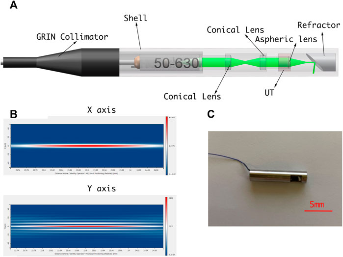
FIGURE 7. (A) Schematic diagram of PAE-enhanced drilling probe. (B) Simulation of Bessel beam. (C) PAE-enhanced drilling probe prototype.
Ex vivo study design
Sample selection, processing, and fixation
To obtain experimental data for pedicle screw implantation, an intact lumbar vertebra of a bovine was chosen for ex vivo studies as the sample comparable to that of a human spine. This is because mammalian spines share similarities in spinal morphology and bone tissue composition. The spine of an adult bovine sacrificed within 3-h was employed for experimental validation. (Age: 3 years, gender: male, weight: 200 kg, vertebra weight: 2.5 kg). Afterward, we used a boning knife to separate the muscle tissue from the spine. The purpose of this step was to make the operation field clearer, and to reduce clutter caused by light shining on the muscle tissue. The intact lumbar vertebra after bone and flesh separation is shown in Figure 8. Afterward, we performed the tissue processing by removing the lumbar vertebra for the subsequent experiments. The entire treated spine was fixed in a transparent acrylic box with glue, and the box filled with water until the tissue was completely covered, in order to significantly reduce attenuation of the PA signal.
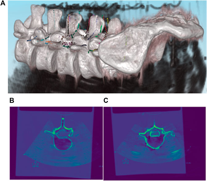
FIGURE 8. Registration results of pre-operative CT and intra-operative 3D US. (A) 3D Rendering of co-registered CT and US images; (B,C) 2D Rendering of co-registered CT and US images.
PAE imaging experimental setup
A PAE drilling probe allows for local-scale navigation in a fine-grained manner to facilitate screw implantation more accurately and safely. A torque-enhancement unit and a PAE probe comprise the overall system. Figures 7A,C provide a schematic diagram and system prototype of the probe. After passing through the neutral-density filter (NDF), the pulse laser generated by the Q-switch laser (532 nm, 7 ns, 10 Hz, Xichanye Co., Ltd., China) is divided into two beams by the beam splitter (BS) (the beam ratio is 1:10). The photodiode receives the lower-energy beam, while the other beam is coupled into the optical fiber after being focused by a collimating filter for subsequent PAE imaging. Both signal lines are relatively thin, since the PAE probe is rotated around the main axis of the drill. As shown in Figure 2B, a mechanical torsion increasing unit was designed to prevent the signal wire from breaking during winding with the optical fibers. The outer layer of the optical fiber at the end of the drilling probe, as well as its signal line, are reinforced with a shrinkable heat tube to ensure a relatively stable connection between the outer layer and the signal line. The drill is connected to one end of the heat-shrinkable tube, and the conductive slide ring to the other. The motor’s torque is transmitted to the conductive slide ring via the outer layer during rotation. Simultaneously, the signal line of the single-element ultrasonic transducer relates to the rotor of the conductive slide ring via a fiber that passes through its hollow slide ring and terminates at the end of the optical excitation unit. Since the optical fiber must be rotated as well, a rolling bearing is added at the end, enabling the optical fiber and the probe signal line to be rotated without winding. The maximum laser energy on the sample is approximately 16 mJ/cm2, far below the ANSI (American National Standards Institute) safety standard (30 mJ/cm2), and the calculation data from UCSB Laser Safety Manual of 19.29 mJ/cm2 (UCSB, 2018) (Thomas et al., 2001).
Results
Registration of pre-operative CT with intra-operative 3D US
As described in the previous section, the most vital task during pedicle screw implantation is determining an appropriate drilling entry and path direction prior to entering the vertebral bone. After the US volume is generated intra-operatively, each vertebral model segmented from pre-operative CT is registered with the point clouds of the bone surface extracted from the US volume, due to the fact that the CT vertebral model can supplement the missing bone structure of the US volume caused by ultrasonic reflection and/or attenuation. As such, it offers a more comprehensive representation of the vertebral bone profile once an inter-vertebral posture variation occurs. As shown in Figure 8, CT data of the lumbar spine are overlain with the spinal sonography in 3D and 2D visualizations. Eventually, based on the co-registered CT and US images, three typical screw implantation paths (i.e., correct path, lateral misplacement, and medial misplacement) are determined (see Figure 9). Along these three coarse paths, the PAE-enhanced drilling probe is advanced for in situ bone tissue sensing inside the vertebra and hence for fine path optimization, which is described in the subsequent section.
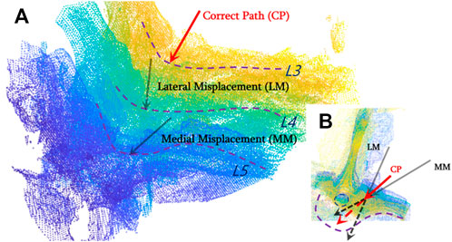
FIGURE 9. Drilling entry point determination and coarse path planning based on co-registered CT and US images for pedicle screw implantation. (A) Three types of screw implantation paths (correct path, lateral misplacement, and medial misplacement) are defined on co-registered CT and US images; (B) 2D visualization of three typical screw implantation paths.
PA signal characterization: Cortical bone vs. cancellous bone
The PA signals of cortical and cancellous bone are acquired and investigated by the single element ultrasonic acquisition system, as described in the previous section. It is noted that the wavelength and power of the excitation laser are constant, and multiple acquisition results are averaged to reduce crosstalk noise. Since the PA image is a composition of multiple signals with a variety of frequencies in general, the obtained images are transformed to the frequency domain using the Fourier transform for signal characterization. The experimental results are shown in the following figures: Figures 10A,C reflect the signal profile of cortical and cancellous bone in the time domain, while figures 10 B,D demonstrate the signal profile of the cortical and cancellous bone in the frequency domain. Of note, under the same laser energy excitation, the PA signal amplitude peak of cortical bone is slightly lower than that of cancellous bone, and the signals are mostly concentrated in the high-frequency section. The signal response of cancellous bone is slightly stronger than that of cortical bone in terms of amplitude.
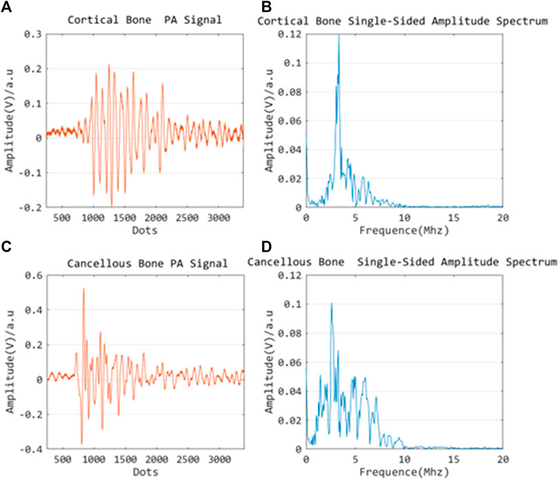
FIGURE 10. Time domain PA signal characterization of cortical bone (A) and cancellous bone (C); Frequency domain PA signal characterization of cortical bone (B) and cancellous bone (D).
In situ PAE sensing via drilling probe
Based on the co-registered CT and US images, three typical screw implantation paths are determined (see Figure 9). Along these three coarse paths, the PAE-enhanced drilling probe advances for in situ bone tissue sensing inside the vertebra and hence for fine path optimization.
Figure 11 indicates the drilling probe insertion along the clinically “correct” implantation path (Correct Path) on the L3 segment of lumbar spine and demonstrates the acquired PAE images. Such PAE images are obtained at 30s intervals. It can be noticed that in the first 90s (see Figures 11A–C), the probe has been delivered into the vertebrae, but has not yet arrived in the pedicle region. During the period of the 90ths∼120ths, it can clearly be seen that the probe has penetrated the pedicle region. The PA signals yielded by the surrounding cancellous bone are presented in Figure 11D, and the cancellous bone is distributed evenly around this drilling probe. As the probe is inserted continuously, the PA images obtained (see Figures 11E–G) show the PA signals yielded by the surrounding cancellous bone are still uniformly distributed near the drilling bit. From the 210ths on, the PA signals induced by the cancellous bone disappear; at this time the drilling probe has been removed from the vertebra (see Figure 11H).
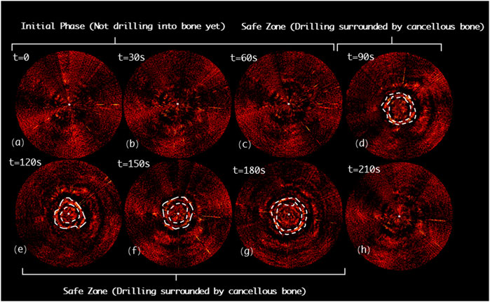
FIGURE 11. Acquired PAE images along the clinically “correct” path (CP) for in situ bone tissue sensing. (A-C) Initial phase; (D-G) Safe zone; (H) Final phase.
Figure 12 shows the drilling probe insertion along the lateral misplacement path (LMP) on the L4 segment of lumbar spine and demonstrates the acquired PAE images. Such a path often results in lateral cortical breach, thereby bringing potential harm to peripheral vessels or nerves. In the first 90s, the associated PAE images are acquired (see Figures 12A-C), and the drill has not yet been inserted into the pedicle region for bone tissue characterization. During the period of 90ths-120ths, the drilling probe enters the pedicle region. As shown in Figure 12D, the probe is evenly surrounded by cancellous bone in a safe position. During the period of 120ths-180ths, the PA signals change in the regions A1 and A2, as highlighted in Figures 12E,F, indicating that new PA signals, different from those of cancellous bone, have been yielded in the regions A1 and A2. Based on anatomical interpretation, the drill bit is thought to be approaching the interface between the cortical bone and cancellous bone within the pedicle region, indicating the drill bit is in the perforation warning zone. As shown in Figure 12G, starting from the 180ths, PA signals like those of the 90ths are observed. This reflects that the drill bit remains inside the pedicle region during insertion, only at some sites the drill bit is close to the cortical bone border of the vertebrae, requiring a warning and further correction.
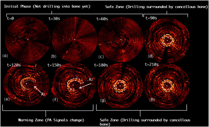
FIGURE 12. Acquired PAE images along the lateral misplacement path (LMP) for in situ bone tissue sensing. (A-C) Initial phase; (D) Safe zone; (E-F) Warning zone; (G-H) Safe zone.
Figure 13 demonstrates the drilling probe insertion along the medial misplacement path (MMP) on the L5 segment of the lumbar spine and demonstrates the acquired PAE images. Such a path frequently results in medial cortical breach, and thereafter causes complications, such as spinal cord injury. In the first 60s, the drill has not yet entered the pedicle region (see Figures 13A,B). As shown in Figures 13C-F, starting from the 60ths, the variation in the PA signals can be clearly detected (region B1 and B2), indicating that the drill bit is not surrounded by cancellous bone at this time. Subsequently, from the 120ths to 180ths, the drill is found to be located inside a perforation warning region (B3 and B4), where the spinal cord may be at high risk of damage. At 210ths, no visible PA signals are detected, revealing that the drill has completely penetrated the medial cortical bone (see Figure 13H).
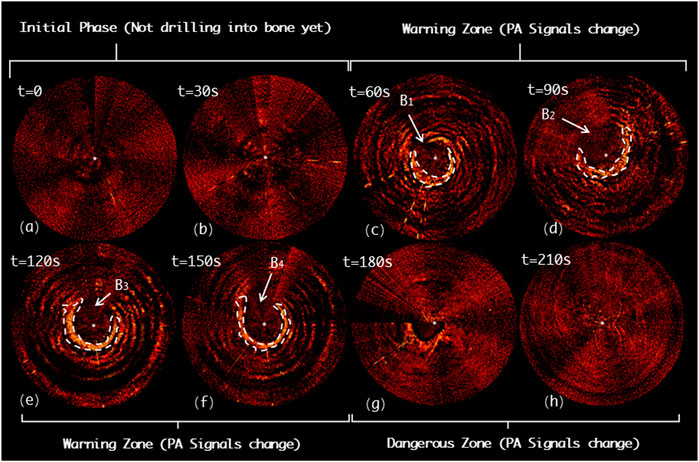
FIGURE 13. Acquired PAE images along the medial misplacement path (MMP) for in situ bone tissue sensing. (A-B) Initial phase; (C-F) Warning zone; (G-H) Dangerous zone.
In order to assess the imaging quality of the PAE images quantitatively, we applied the generalized contrast-to-noise ratio (gCNR) as a metric. The gCNR is a relatively new image quality metric designed to assess the probability of lesion detectability in ultrasound images (Kempski et al., 2020). The gCNR metric is calculated from the overlap of the probability density functions (PDFs) of ROIs inside a target and background. The calculation method can be described in the following formula:
where
Discussion and conclusion
In this study, we developed for the first time a radiation-free and multi-scale navigation and sensing system by applying a PAE-enhanced drilling probe to facilitate pedicle screw implantation optimization. Existing studies either only consider global spatial navigation based on macroscopic anatomical imaging (fluoroscopy or CBCT with radiation; combined US/PAT without radiation) or only take in situ tissue sensing, using local sensor-enhanced instruments (acceleration/force sensor; electrical conductivity measurement; EUS probe), into consideration.
The main novelty of this pilot study is that we combine the advantages of global spatial navigation and local tissue sensing techniques. Specifically, the comprehensive navigation system provides global context-awareness from the macroscopic 3D US imaging. 3D US imaging was established for online status updates of the position of the spinal segment to determine an appropriate entry point and coarse drilling path once non-negligible patient motion or relative motion between inter-vertebral segments occurs intra-operatively. The PAE-enhanced drilling probe is subsequently used along the planned coarse insertion path to recognize cortical bone and cancellous bone tissue inside the vertebra near the drill bit for fine orientation correction. To the best of our knowledge, for the first time here, a PAE-enhanced drilling probe is designed, developed, and deployed for pedicle screw implantation in spinal fusion. The ex vivo experiment on a bovine spine demonstrates the clinical feasibility of the proposed system, which holds great potential for allowing functionally accurate screw implantation for spine stabilization in complex spine-related interventions. Table 2 demonstrates the advantages and disadvantages of a variety of existing navigation and sensing technologies for pedicle screw implantation. Compared with other state-of-the-art techniques, PA-enabled solutions (either PAT/US macroscopic dual-modal imaging, or PAE-enhanced drilling probe for in situ tissue sensing at clinically relevant mesoscopic scale), reveal advantages of non-radiation, high efficacy, moderate deployment complexity, better image quality (gCNR value), and local signal direction information, and hold great potential for facilitating radiation-free and minimally invasive pedicle screw placement.
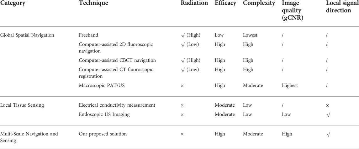
TABLE 2. Comparison of a variety of navigation and sensing techniques for pedicle screw implantation.
However, the challenges of implementing the PAE-enhanced drilling probe for spine stabilization need to be addressed. The size of the PAE-enhanced drilling probe should be more compact, such that its application in clinical practice can meet the need of extremely deformed spine cases, where the pedicle region where the screw is to be implanted is further restricted to 1–2 mm, or even sub-millimeter. Of note, a more compact design scheme based on an optical fiber sensing solution is being investigated to replace the piezoelectrical US transducer.
In addition, the ns-pulse laser utilized to generate photoacoustic signals tends to be too expensive compared to other techniques, such as acceleration/force sensors, electrical conductivity measurement probes, and EUS probes. Despite this, the PAE-enhanced drilling probe still holds significant advantages over its counterparts, such as better images, more intuitive visual feedback, and local signal directional information for tissue differentiation and warning. Fortunately, many cost-effective laser sources have become commercially available. It is noted that these could offer a great opportunity to reduce the cost of the PAE-enhanced drilling probe for spinal stabilization in clinical practice.
Since it is difficult to measure the absorption spectrum of solids based on our available measuring instrument, we applied grinding to convert the solid cancellous bone into a powder-like form. We also compared the effect of the degree of grinding on the results of the absorption spectrum, which deviates from the actual absorption spectrum. In addition, the absorption spectrum of solid cortical bone could not be readily tested due to its high density and difficulty in grinding it into powder form. To solve this problem, we measured actual PA signals to distinguish between different tissues. In other words, it elaborates the different absorption resulting from the different composition of solid tissues.
As the morphological characteristics of the cancellous bone in vivo are porous and blood-filled, there may be errors due to continuous reflection of the PA signal within the pores during the imaging process. Therefore, our experimental results reveal the relative deviation between the cortical and cancellous bone site in the image at the same test point, and this deviation can help us to differentiate the site. Since the rotation and feed along the axis of the PAE probe is achieved by a surgical drill, the PAE-enhanced straight drill can only accurately serve the function of detecting the safety of the drilled hole. Our future work would be to develop a steerable drilling robot that can avoid dangerous collision situations during surgery.
Data availability statement
The raw data supporting the conclusion of this article will be made available by the authors, without undue reservation.
Author contributions
All authors listed have made a substantial, direct, and intellectual contribution to the work, and approved it for publication. LL (First Author, Corresponding Author): Conceptualization, Methodology, Software, Supervision, Funding Acquisition, Writing-Original Draft; YZ (First Author): Data Curation, Methodology, Formal Analysis, Visualization, Writing-Original Draft; AL: Visualization, Software, Investigation; XY: Investigation, Validation; XX: Investigation, Validation; SL (Corresponding Author): Funding Acquisition, Resources, Supervision, Writing-Review & Editing; MM: Funding Acquisition, Resources, Supervision.
Funding
This work was supported by the National Key R&D program of China with Grant No. 2019YFB1312400; the Hong Kong Research Grants Council (RGC) Collaborative Research Fund (CRF C4026-21GF and CRF C4063-18G); the General Research Fund (GRF #14220622, GRF #14204321, and GRF#14211420); and the Natural Science Foundation of Jiangsu Province (Grant No. BK20210323).
Conflict of interest
The authors declare that the research was conducted in the absence of any commercial or financial relationships that could be construed as a potential conflict of interest.
Publisher’s note
All claims expressed in this article are solely those of the authors and do not necessarily represent those of their affiliated organizations, or those of the publisher, the editors, and the reviewers. Any product that may be evaluated in this article, or claim that may be made by its manufacturer, is not guaranteed or endorsed by the publisher.
References
Ahern, D. P., Gibbons, D., Schroeder, G. D., Vaccaro, A. R., and Butler, J. S. (2020). Image-guidance, robotics, and the future of spine surgery. Clin. Spine Surg. 33 (5), 179–184. doi:10.1097/bsd.0000000000000809
Aly, A. H., Ginsberg, H. J., and Cobbold, R. S. C. (2011). ON ultrasound imaging for guided screw insertion in spinal FUSION surgery. Ultrasound Med. Biol. 37 (4), 651–664. doi:10.1016/j.ultrasmedbio.2011.01.011
An, H., and Benoit, P. (1998). Saline injection technique to confirm pedicle screw path: A cadaveric study. Am. J. Orthop. 27, 362–365.
Beard, P. (2011). Biomedical photoacoustic imaging. Interface Focus 1 (4), 602–631. doi:10.1098/rsfs.2011.0028
Bolger, C., Kelleher, M. O., McEvoy, L., Brayda-Bruno, M., Kaelin, A., Lazennec, J. Y., et al. (2007). Electrical conductivity measurement: A new technique to detect iatrogenic initial pedicle perforation. Eur. Spine J. 16 (11), 1919–1924. doi:10.1007/s00586-007-0409-8
Chapman, J. R. (2019). Editorial. Spinal infections: A growing problem, which deserves our urgent attention. Neurosurg. FOCUS 46 (1), E3. doi:10.3171/2018.10.focus18587
Compston, J. E., McClung, M. R., and Leslie, W. D. (2019). Lancet 393 (10169), 364–376. doi:10.1016/s0140-6736(18)32112-3
Cool, J., van Schuppen, J., de Boer, M. A., and van Royen, B. J. (2021). Accuracy assessment of pedicle screw insertion with patient specific 3D-printed guides through superimpose CT-analysis in thoracolumbar spinal deformity surgery. Eur. Spine J. 30 (11), 3216–3224. doi:10.1007/s00586-021-06951-9
Dea, N., Fisher, C. G., Batke, J., Strelzow, J., Mendelsohn, D., Paquette, S. J., et al. (2016). Economic evaluation comparing intraoperative cone beam CT-based navigation and conventional fluoroscopy for the placement of spinal pedicle screws: A patient-level data cost-effectiveness analysis. Spine J. 16 (1), 23–31. doi:10.1016/j.spinee.2015.09.062
Duffy, M. F., Phillips, J. H., Knapp, D. R., and Herrera-Soto, J. A. (2010). Usefulness of electromyography compared to computed tomography scans in pedicle screw placement. SPINE 35 (2), E43–E48. doi:10.1097/brs.0b013e3181b3f467
Felix, B., Kalatar, S. B., Moatz, B., Hofstetter, C., Karsy, M., Parr, R., et al. (2022). Augmented reality spine surgery navigation increasing pedicle screw insertion accuracy for both open and minimally invasive spine surgeries. SPINE 47 (12), 865–872. doi:10.1097/brs.0000000000004338
Foley, K. T., Simon, D. A., and Rampersaud, Y. R. (2001). Virtual fluoroscopy: Computer-assisted fluoroscopic navigation. SPINE 26 (4), 347–351. doi:10.1097/00007632-200102150-00009
Germon, T. J., and Hobart, J. C. (2015). Definitions, diagnosis, and decompression in spinal surgery: Problems and solution. Spine J. 15 (3), 5S–8S. doi:10.1016/j.spinee.2014.12.147
Gonzalez, E. A., Jain, A., and Bell, M. A. L. (2021). Combined ultrasound and photoacoustic image guidance of spinal pedicle cannulation demonstrated with intact ex vivo specimens. IEEE Trans. Biomed. Eng. 68 (8), 2479–2489. doi:10.1109/tbme.2020.3046370
Guo, H., Li, Y., Qi, W., and Xi, L. (2020). Photoacoustic endoscopy: A progress review. J. Biophot. 13, e202000217. doi:10.1002/jbio.202000217
Hecht, N., Yassin, H., Czabanka, M., Föhre, B., Arden, K., Liebig, T., et al. (2018). Intraoperative computed tomography versus 3D C-arm imaging for navigated spinal instrumentation. Spine 43 (5), 370–377. doi:10.1097/brs.0000000000002173
Helm, P. A., Teichman, R., Hartmann, S. L., and Simon, D. (2015). Spinal navigation and imaging: History, trends, and future. IEEE Trans. Med. Imaging 34 (8), 1738–1746. doi:10.1109/tmi.2015.2391200
Ibtehaz, N., and Rahman, M. S. (2020). MultiResUNet : Rethinking the U-Net architecture for multimodal biomedical image segmentation. NEURAL Netw. 121, 74–87. doi:10.1016/j.neunet.2019.08.025
Jolliffe, I. T., and Cadima, J. (2016). Principal component analysis: A review and recent developments. PHILOSOPHICAL Trans. R. Soc. A-MATHEMATICAL Phys. Eng. Sci. 374 (2065), 20150202. doi:10.1098/rsta.2015.0202
Joon-Mo Yang, K. M., Yang, H-C., Zhou, Q., Kirk Shung, K., and Wang, L. V. (2009). Photoacoustic endoscopy. Opt. Lett. 34 (10), 1591–1593. doi:10.1364/ol.34.001591
Kempski, K. M., Graham, M. T., Gubbi, M. R., Palmer, T., and Lediju Bell, M. A. (2020). Application of the generalized contrast-to-noise ratio to assess photoacoustic image quality. Biomed. Opt. Express 11 (7), 3684–3698. doi:10.1364/boe.391026
Kruizinga, P., van der Steen, A. F., de Jong, N., Springeling, G., Robertus, J. L., van der Lugt, A., et al. (2014). Photoacoustic imaging of carotid artery atherosclerosis. J. Biomed. Opt. 19 (11), 110504. doi:10.1117/1.jbo.19.11.110504
Li, Q., Du, Z., Liu, F., and Yu, H. (2022). Tactile perception for surgical status recognition in robot-assisted laminectomy. IEEE Trans. Ind. Electron. 69 (11), 11425–11435. doi:10.1109/tie.2021.3118387
Li, X., Xiong, K., and Yang, S. (2019). Large-depth-of-field optical-resolution colorectal photoacoustic endoscope. Appl. Phys. Lett. 114 (16), 163703. doi:10.1063/1.5093789
Lonstein, J. E., Denis, F., Perra, J. H., Pinto, M. R., Smith, M. D., and Winter, R. B. (1999). Complications associated with pedicle screws. J. Bone Jt. Surg. 81 (11), 1519–1528. doi:10.2106/00004623-199911000-00003
Lopera, J. E., Restrepo, C. S., Gonzales, A., Trimmer, C. K., and Arko, F. (2010). Aortoiliac vascular injuries after misplacement of fixation screws. J. Trauma Inj. Infect. Crit. Care 69 (4), 870–875. doi:10.1097/ta.0b013e3181f0bd55
Manbachi, A., Cobbold, R. S. C., and Ginsberg, H. J. (2014). Guided pedicle screw insertion: Techniques and training. Spine J. 14 (1), 165–179. doi:10.1016/j.spinee.2013.03.029
Maria, S., Deyanira, C., Francesca, S., Lucia, M., Alessandro, R., Silvia, T., et al. (2020). Spinal fusion surgery and local antibiotic administration A systematic review on Key points from preclinical and clinical data. SPINE 45 (5), 339–348. doi:10.1097/brs.0000000000003255
Mujagic, M., Ginsberg, H. J., and Cobbold, R. S. C. (2008). Development of a method for ultrasound-guided placement of pedicle screws. IEEE Trans. Ultrason. Ferroelectr. Freq. Control 55 (6), 1267–1276. doi:10.1109/tuffc.2008.789
Nottmeier, E. W., and Crosby, T. L. (2007). Timing of paired points and surface matching registration in three-dimensional (3D) image-guided spinal surgery. J. SPINAL Disord. Tech. 20 (4), 268–270. doi:10.1097/01.bsd.0000211282.06519.ab
Ovadia, D., Korn, A., Fishkin, M., Steinberg, D. M., Wientroub, S., and Ofiram, E. (2011). The contribution of an electronic conductivity device to the safety of pedicle screw insertion in scoliosis surgery. SPINE 36 (20), E1314–E1321. doi:10.1097/brs.0b013e31822a82ec
Sangha, G. S., and Goergen, C. J. (2016). Photoacoustic tomography: Applications for atherosclerosis imaging. J. Opt. 18 (8), 084005. doi:10.1088/2040-8978/18/8/084005
Shi, Q., Xi, N., Chen, Y. F., and Sheng, W. H. (2006). “Ieee. Registration of point clouds for 3D shape inspection,” in IEEE/RSJ INTERNATIONAL CONFERENCE ON INTELLIGENT ROBOTS AND SYSTEMS, Beijing, China, 09-15 October 2006, 235.
Shubert, J., and Lediju Bell, M. A. (2018). Photoacoustic imaging of a human vertebra: Implications for guiding spinal fusion surgeries. Phys. Med. Biol. 63 (14), 144001. doi:10.1088/1361-6560/aacdd3
Steinberg, I., Huland, D. M., Vermesh, O., Frostig, H. E., Tummers, W. S., and Gambhir, S. S. (2019). Photoacoustic clinical imaging. Photoacoustics 14, 77–98. doi:10.1016/j.pacs.2019.05.001
Tabarestani, T. Q., Sykes, D., Murphy, K. R., Wang, T. Y., Shaffrey, C. I., Goodwin, C. R., et al. (2022). Beyond placement of pedicle screws-new applications for robotics in spine surgery: A multi-surgeon, single-institution experience. Front. Surg. 9, 889906. doi:10.3389/fsurg.2022.889906
Thomas, R., Rockwell, B., Marshall, W., Aldrich, R., and Zimmerman S, R. (2001). A procedure for multiple-pulse maximum permissible exposure determination under the Z136.1-2000 American National Standard for Safe Use of Lasers. J. Laser Appl. 13, 134–140. doi:10.2351/1.1386796
Tian, N. F., Huang, Q. S., Zhou, P., Zhou, Y., Wu, R. K., Lou, Y., et al. (2011). Pedicle screw insertion accuracy with different assisted methods: A systematic review and meta-analysis of comparative studies. Eur. Spine J. 20 (6), 846–859. doi:10.1007/s00586-010-1577-5
Wang, Y. X. J., Che-Nordin, N., Leung, J. C. S., Yu, B. W. M., Griffith, J. F., and Kwok, T. C. Y. (2020). Elderly men have much lower vertebral fracture risk than elderly women even at advanced age: The MrOS and MsOS (Hong Kong) year 14 follow-up radiology results. Arch. Osteoporos. 15 (1), 176. doi:10.1007/s11657-020-00845-x
Weiss, A., Elixhauser, A., and Steiner, C. Readmissions to U.S. Hospitals by procedure, 2010: Statistical Brief #154. 2008.
Xu, M., and Wang, L. V. (2006). Photoacoustic imaging in biomedicine. Rev. Sci. Instrum. 77 (4), 041101. doi:10.1063/1.2195024
Yamada, T., Hasegawa, T., Yamato, Y., Yoshida, G., Banno, T., Arima, H., et al. (2022). Characteristics of pedicle screw misplacement using freehand technique in degenerative scoliosis surgery. ARCHIVES Orthop. TRAUMA Surg. doi:10.1007/s00402-022-04380-x
Yao, J., and Wang, L. V. (2013). Photoacoustic microscopy. Laser Phot. Rev. 7 (5), 758–778. doi:10.1002/lpor.201200060
Zhang, J., Li, W. S., Hu, L., Zhao, Y., and Wang, T. M. (2021). A robotic system for spine surgery positioning and pedicle screw placement. Int. J. Med. Robot. 17 (4), e2262. doi:10.1002/rcs.2262
Zhao, T., Desjardins, A. E., Ourselin, S., Vercauteren, T., and Xia, W. (2019). Minimally invasive photoacoustic imaging: Current status and future perspectives. Photoacoustics 16, 100146. doi:10.1016/j.pacs.2019.100146
Keywords: multi-scale navigation and sensing, ultrasound-based surgical navigation, photoacoustic endoscopy, robotic-assisted spinal surgery, cancellous bone characterization, in situ tissue sensing, pedicle screw implantation
Citation: Liu L, Zhao Y, Li A, Yu X, Xiao X, Liu S and Meng MQ-H (2022) A photoacoustics-enhanced drilling probe for radiation-free pedicle screw implantation in spinal surgery. Front. Bioeng. Biotechnol. 10:1000950. doi: 10.3389/fbioe.2022.1000950
Received: 22 July 2022; Accepted: 15 August 2022;
Published: 15 September 2022.
Edited by:
Kawsar Ahmed, Mawlana Bhashani Science and Technology University, BangladeshReviewed by:
Md Bellal Hossain, The University of Sydney, AustraliaShobhit K. Patel, Marwadi University, India
Shaymaa Tahhan, Shaymaa Riyadh Tahhan, Iraq
Copyright © 2022 Liu, Zhao, Li, Yu, Xiao, Liu and Meng. This is an open-access article distributed under the terms of the Creative Commons Attribution License (CC BY). The use, distribution or reproduction in other forums is permitted, provided the original author(s) and the copyright owner(s) are credited and that the original publication in this journal is cited, in accordance with accepted academic practice. No use, distribution or reproduction is permitted which does not comply with these terms.
*Correspondence: Li Liu, liliu@cuhk.edu.hk; Siyu Liu, syliu@njust.edu.cn
†These authors have contributed equally to this work
 Li Liu
 Yongjian Zhao1†
  Xiao Xiao