Non-back-drivable clutch based self-locking mechanism of prosthetic joint to improve manipulation stability
 Yang Liu1†
  Yuhui Luo
 Jiejunyi Liang
- 1State Key Laboratory of Intelligent Manufacturing Equipment and Technology, Huazhong University of Science and Technology, Wuhan, China
- 2School of Art, Soochow University, Suzhou, China
- 3Huazhong University of Science and Technology Hospital, Wuhan, China
During activities of daily living (ADLs), the wrist is mainly engaged in positioning and directing the hand. Researches have demonstrated that restoring wrist mobility can significantly enhance the manipulation ability, reduce body distortion caused by motion compensation, and improve the quality of life for amputees. However, most daily activities, particularly the delicate ones, place high demands on the ability of wrist to maintain a certain rotation angle, also known as non-back-drivable ability, which poses a challenge to the design of prosthetic wrists. To address this issue, various solutions have been proposed, including motor holding brakes, high reduction ratio reducers, and worm gears. However, the motor holding brake only functions after a power outage and cannot continuously prevent torque from the load end. The latter two solutions may alter the transmission ratio, resulting in reduced movement speed and transmission efficiency. Therefore, how to design a miniaturized non-back-drivable mechanism without changing the transmission ratio so that the forearm rotational freedom can be locked at any position for any duration is a problem to be solved in the research of prosthetic wrist designs. This paper presents a line-contact based non-back-drivable clutch (NBDC) that does not cause changes in the transmission ratio, ensuring the motion performance of the prosthetic limb. At the same time, it does not introduce additional friction in the forward transmission process, guaranteeing the overall efficiency. Most importantly, it only allows the torque transmitting from the motor to the load, prevents the load reversely from driving back even in a power failure condition, significantly improving the stability, safety, and comfort. Detailed kinematic and static analyses of the working process has been conducted, and transient dynamics simulation has been performed to verify its effectiveness. Through experiments, it is demonstrated that the self-locking torque of the output end could reach approximately 600 Nmm, and the unlocking torque of the input end is about 80 Nmm, which can be effectively integrated in prosthetic wrist rotation joints, contributing to the performance, safety and energy saving of prosthetic joint systems.
1 Introduction
The rotation of the human forearm relies on the ulna and radius turning from a parallel state to an intersecting state. The successful realization of this movement depends on the complete distal radioulnar joint (Neumann, 2016). However, transradial amputation is the most common form of upper limb amputation, which leads to the inevitable destruction of the distal radioulnar joint. As the degree of amputation increases, the rotation ability of the residual limb decreases sharply. Even with a prosthetic hand, the patient’s ADLs are still greatly restricted due to the lack of the most important rotation function of the wrist. In this case, to achieve motion compensation, amputee’s body would inevitably be distorted during manipulation scenarios, which would not only seriously affect the amputee’s comfort, but also bring depression and anxiety to them (Bandara et al., 2014; Semasinghe et al., 2018; Billones et al., 2020). Moreover, it has been discovered that compared with further improving the performance of prosthetic hand, it is more effective to employ a prosthetic wrist to achieve a substantial overall improvement (Montagnani et al., 2015a; Deijs et al., 2016; Bajaj et al., 2019; Lee et al., 2021).
A survey of upper-limb prosthetic users showed that features such as lightweight, durability, and long duration of single charge (more than 12 h) are directly related to whether prosthetic products will be accepted (Mustafa et al., 2006), and among which, lightweight is the most important (Biddiss et al., 2007). Therefore, commercially available prosthetic wrists generally adopt designs those only have a single degree of freedom, retaining the most important rotational freedom to meet the lightweight needs. However, during manipulation tasks, the wrist plays a crucial role in precise positioning the prosthetic hand before the hand comes into contact with the target, and is heavily involved in maintaining stability of the target during the contact, which excessively requires the non-back-drivable ability of the rotating component. To address this issue, various solutions have been proposed, including motor holding brakes, high reduction ratio reducers, and worm gears. However, the motor holding brake only functions after a power outage and cannot continuously prevent torque from the load end (Ann et al., 2000). The latter two solutions may alter the transmission ratio, resulting in reduced movement speed and transmission efficiency. Therefore, how to design a miniaturized non-back-drivable mechanism without changing the transmission ratio so that the forearm rotational freedom can be locked at any position for any duration is a problem to be solved in the research of prosthetic wrists (Controzzi et al., 2010; Kimura et al., 2021; Shi et al., 2021), and is critical to the successful completion of the manipulation task (Gao et al., 2021). In most grasping actions which require to maintain the locking state for a long time, if the actuator lacks a self-locking mechanism, the external load will directly act on the drive motor and drive the prosthetic wrist in the opposite direction, resulting in not only an unstable wrist rotation angle, but also a potential hazard (Guo et al., 2020; Wei et al., 2023). This hazard would be exacerbated in the event of a power failure due to a depleted battery or circuit failure. The unlocked wrist joint will rotate freely under the action of the external load, posing a great danger to amputees. Therefore, prosthetic joints that take into account both miniaturization requirements and self-locking capabilities have become the main development trend, and the key component is the non-back-drivable clutch.
To be specific, the input end of the NBDC is the power system such as the drive motor, and the output end is connected to the hand and the external loads. When the input end receives a motion command and the motor starts to rotate, whether it is clockwise rotation or counterclockwise, as long as the initial torque is greater than the unlocking torque, the transmission system can be activated to achieve efficient power transmission. To the contrary, regardless of whether the external loads apply clockwise or counterclockwise torque to the NBDC, as long as it is within the maximum self-locking torque range, the mechanism will automatically enter the locking state, so that the external loads will not directly affect the drive motor. This feature gives the prosthetic joint the ability to maintain stable grasping at any position for a long time. It also possesses the ability to function without power supply during operation that does not need further rotating, extending the battery life to a certain extent. Therefore, designing advanced NBDC and continuously optimizing its self-locking performance can effectively improve the stability, safety, and endurance of prosthetic joints (Liu et al., 2022).
Researches focusing on how to improve NBDC performance have concluded five optimization directions (Chu et al., 2008; Controzzi et al., 2010; Controzzi et al., 2017; Montagnani et al., 2015b; Hu et al., 2021; Wu et al., 2023): (1) Low cost. In order to meet the large-scale production and implementation of self-locking mechanisms, the cost of related components need to reasonably controlled (Liu et al., 2021) while ensuring the performance and quality (Mota et al., 2023). (2) Simplicity (Zhang et al., 2023), including miniaturization (Ding et al., 2021) and ease of manufacturing and assembly (Controzzi et al., 2010). (3) Safety. Due to the sufficient interaction between humans and prosthetic limbs(Lu et al., 2021), safety is the primary concern in real practice (Hu et al., 2020). If the external load can reversely drive the prosthetic joints, it will cause secondary damage to the amputees. (4) Energy efficiency. How to improve the battery duration of a single charge has always been an important topic in the field of prosthetics (Cirelli et al., 2021; Okafor and Longe, 2022; He et al., 2023). If a single charge cannot satisfy an amputee’s normal use for a day, it will greatly affect its acceptance. As a result, reducing the friction energy loss and inertia would be of great importance (Cirelli et al., 2021). (5) Robustness. As the external load is determined by the actual manipulation tasks, the nominal self-locking torque should be high enough to cover most daily working scenarios.
Focusing on the above five requirements, Marco Controzzi et al. (Controzzi et al., 2010; Controzzi et al., 2017) designed a cylinder-based NBDC and applied it in the SmartHand (Cipriani et al., 2010), enabling it to effectively generate strong gripping force under strict power and weight constraints. Compared with the traditional non-back-drivable mechanism based on worm gears (Kang et al., 2015), this clutch, based on a wedge structure, achieves higher transmission efficiency. Within the load range from 50 Nmm to 150 Nmm, the maximum efficiency of this mechanism is around 0.95. Jun-Uk Chu et al. embedded a self-locking mechanism in the prosthetic finger joint (Chu et al., 2008). The self-locking mechanism adopts a coil spring and cam ball structure to prevent the reverse force of the grasped object on the fingers. However, the springs and cams in this mechanism suffer significant wear during operation, which does not meet the durability requirements of prosthetic devices. Qiqiang Hu et al. (Hu et al., 2021)were inspired by the ratchet spanner and employed an interlock to increase the grip strength of the fingers, enabling them to safely perform high loads and prolonged gripping tasks. However, when the ratchet mechanism is unlocking, it is always in a state of friction with the buckle and is prone to wear. At the same time, there is a certain amount of free travel in the self-locking process, resulting a small deviation at the load end. Xiaofeng Wu et al. (Wu et al., 2023) proposed a compact arc-groove self-locking mechanism with two linear springs embedded in the arc grooves, eliminating the need for additional mounting structures. The whole system is compact, small, and modular, enabling underdriven finger mechanisms to achieve adaptive gripping. However, the groove needs to be regularly filled with an appropriate amount of grease to reduce the impact of friction between the spring and the groove. Federico Montagnani et al. (Montagnani et al., 2015b) designed a non-back-drivable mechanism for miniaturized application scenarios such as finger joints. This mechanism can turn off the power after reaching a stable state, thereby avoiding accidental release of the grasped object, and absorbs the impact generated during grasping. However, this mechanism must also consider the corrosion of lubricants, etc., limiting its application in certain conditions. In summary, for the existing self-locking mechanisms, there are still unsolved problems such as not being able to lock instantly, excessive wear of the system under normal operating conditions, and the need to add grease to the mechanism in a timely manner.
In this study, in order to solve the above problems, a novel NBDC is proposed, which achieves self-locking based on the line-contact between the wedges and the fixed support, and can be applied in prosthetic wrists to realize rotational self-locking. The proposed mechanism consists of a fixed support, a wedge pedestal, four wedges, a pin pedestal and four pins, meriting low cost and simplicity in manufacture and assembly. As to the operating mechanism, it mainly contains three key states: (1) Self-locking state. No matter whether the output end, which is connected to the external loads, moves clockwise or counterclockwise, the loads cannot be transmitted back to the input end. (2) Intermediate state of unlocking. 7° of idle angle exists between unlock state and complete lock state. (3) Unlocking state. When the torque at the input end drives the pin to rotate more than 7° of idle angle and reach 14°, the driving force would be transmitted to the output end, and then the self-locking system start to rotate as a whole. Simulations and Experiments have been conducted and verified that the self-locking structure could resist a reverse torque of 600 Nmm from the output end, and only requires an unlocking torque about 80 Nmm at the input end, making it highly efficient for the implementation in prosthetic wrists or other rotating joints.
The main contributions of this paper are as follows:
(1) A non-back-drivable clutch with self-locking features is designed, which does not change the transmission ratio of the system and can ensure the motion speed of the rotating forearm under the premise of stable manipulation. (2) A wavy spring with suitable stiffness is designed to switch between unlocking and locking modes in the self-locking system, separating the wedges from the support in the unlocking state, reducing the friction and improving the efficiency. (3) Critical working conditions of the self-locking system are analyzed and verified through detailed kinematic analysis, static analysis, transient dynamic simulations and experiments, proving the performance of the proposed system that the self-locking ability reaches 600 Nmm.
The rest of this study is organized as follows. Section 2 introduces the overall design of the new NBDC mechanism, and calculates the theoretical performance of the mechanism through kinematic analysis, static analyses and transient dynamics analysis. Section 3 introduces the experimental platform construction and result analysis of NBDC. Section 4 introduces applications with NBDC embedded in a prosthetic wrist. Section 5 discusses the limitations of this research and possible improvements in the future. The final conclusions can be found in Section 6.
2 Materials and methods
The proposed NBDC based on line-contact self-locking mechanism mainly consists of a fixed support, four wedges, a wedge pedestal, four pins and a pin pedestal. The pin pedestal can be used as the connection to the input end, through which the power system such as the motor could be connected. Four pins are mounted along the circumference of the pin pedestal, the pin drives two sets of wedges to rotate, ultimately generating a self-locking state, an unlocking intermediate state and an unlocking state together with the fixed support (see in Figure 1). Each wedge set is composed of two opposite wedges, connected by a wavy spring in the middle. The shape of each set of wedges is mirror symmetrical. The groove below the wedge connects the pin, and the groove presents a “V” shape. The fixed support is connected to the work platform through bolts, and also connected to the pin pedestal through bearings and pins. Its function is to provide self-locking through the friction between its inner wall and the top arc surface of the wedge in self-locking stage, absorbing the impact from the output end. This clutch is embedded between the wrist rotation motor and the harmonic reducer in practice, with its input end connected to the output shaft of the motor and its output end connected to the harmonic reducer. The specific section view and exploded view of the NBDC mechanism are shown in Figures 2A, B, respectively.
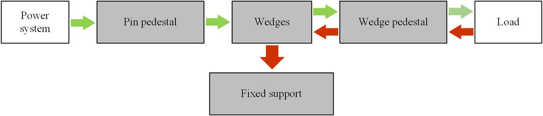
Figure 1. Driving mode (green arrow) and self-locking mode (red arrow) of the NBDC mechanism.
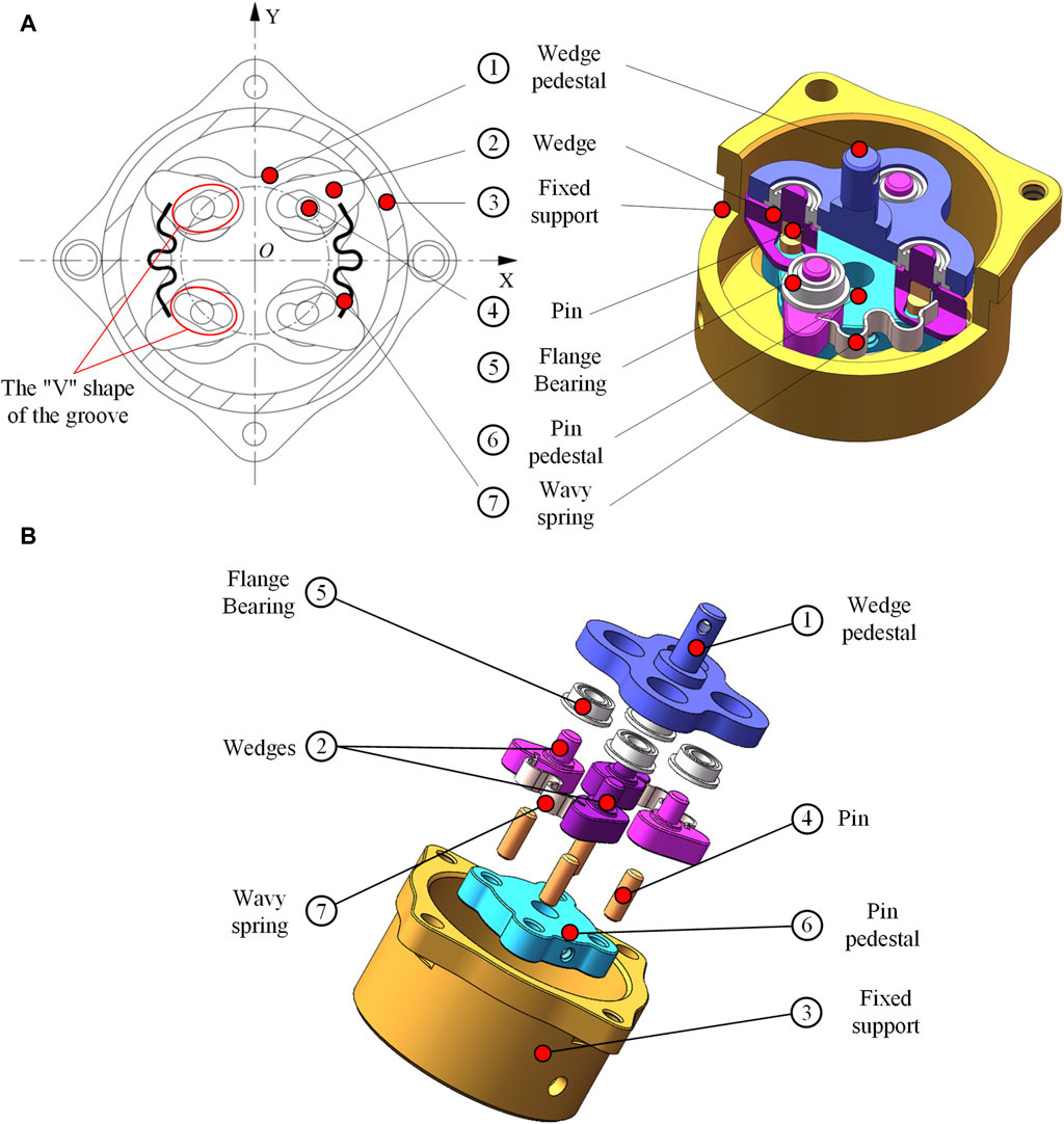
Figure 2. NBDC section view and exploded view. (A) Section view. (B) Exploded view.
2.1 Kinematic analysis
In order to clearly describe the operating mechanism of the proposed NBDC, the section views of five key states of the self-locking mechanism are depicted in detail in Figure 3. These section views are drawn along the middle of the axis with the spring neglected, showing the changes of the input end. These five states can be further divided into three categories, which are: (1) Self-locking, as shown in Figure 3A. In this state, the pin pedestal is at zero point, and the pins don’t contact the inner wall of the groove below the wedges. The torque from the output end cannot be transmitted to the input end whether the motion is clockwise nor counterclockwise, and at the same time, the length of the wavy spring is the longest. (2) Intermediate state of unlocking, as shown in Figures 3B, D. The input end drives the pins through the pin pedestal to rotate 7° around the rotation center. Among the four pins, two of them pressure to the inner wall of the groove under the wedge, making it start to rotate. At the same time, the other two pins just reach the contacting point to the surface of the grooves of the above wedge. At this point, in the 2nd and 4th quadrants of Figures 3A, B gap forms between the edge of the wedges and the inner wall of the fixed support. Similarly, in the 1st and 3rd quadrants of Figures 3A, D gap also appears. (3) Unlocking state. The two pins that have been separated from the fixed support move in the groove during the rotation of 7°–14°, and finally reach the bottom of the groove. The other two pins drive their corresponding wedges to start moving, causing them to break away from the fixed support and eventually reach the bottom of the groove, as shown in the 1st and 3rd quadrants in Figure 3C and the 2nd and 4th quadrants in Figure 3E. Thereafter, the torque at the input end can be transmitted directly to the output, and the wavy spring is compressed to its shortest length. When there is no continuous torque input at the input end, the two springs will exert the stored elastic potential energy to press the wedges to the self-locking state again, back to Figure 3A, so that the torque of the external load will be blocked.
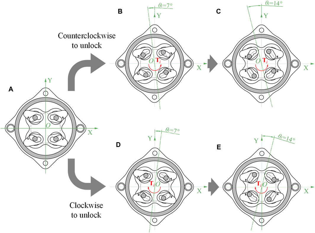
Figure 3. Five key states of the NBDC mechanism (spring not drawn). (A) Self-locking state. (B) Counterclockwise intermediate state of unlocking. (C) Counterclockwise unlocking state. (D) Clockwise intermediate state of unlocking. (E) Clockwise unlocking state.
To investigate the influence of the angle change of the input end on the angle of the wedges in the three working states, kinematic analysis was carried out, taking the 1st and 4th quadrants as examples. As shown in Figure 4A, the inner diameter of the fixed support is
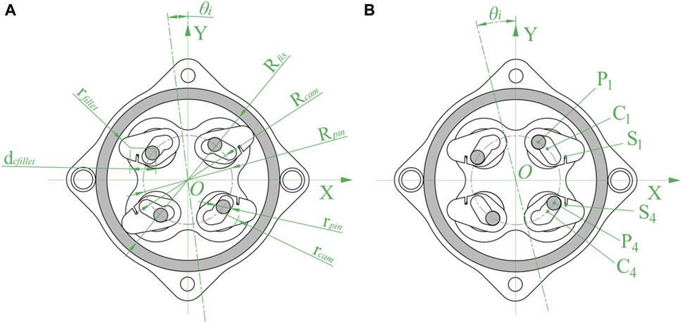
Figure 4. Kinematic analysis of NBDC mechanism (spring not drawn). (A) Dimensions. (B) Action points.
Taking the counterclockwise movement of the input as an example, the positions of the centers of the pins in the 1st and 4th quadrants at any moment are shown in Eq. 1:
The axis where the wedges are located are uniformly distributed along the center, the angle between them is 90°, and the specific position is related to the rotation angle
When the pin pedestal rotates
(1) According to the geometric relationship that the pin in the 4th quadrant is always tangent to the inner side of the groove of the wedge, it can be seen that the slope between the axis of the wedge and the axis of the pin satisfies the following Eq. 3:
Similarly, the slope between the axis of the wedge and the axis of the pin in the 1st quadrant satisfies Eq. 4:
The initial angle of the wedge in the 1st quadrant is
The relationship between the input rotation angle
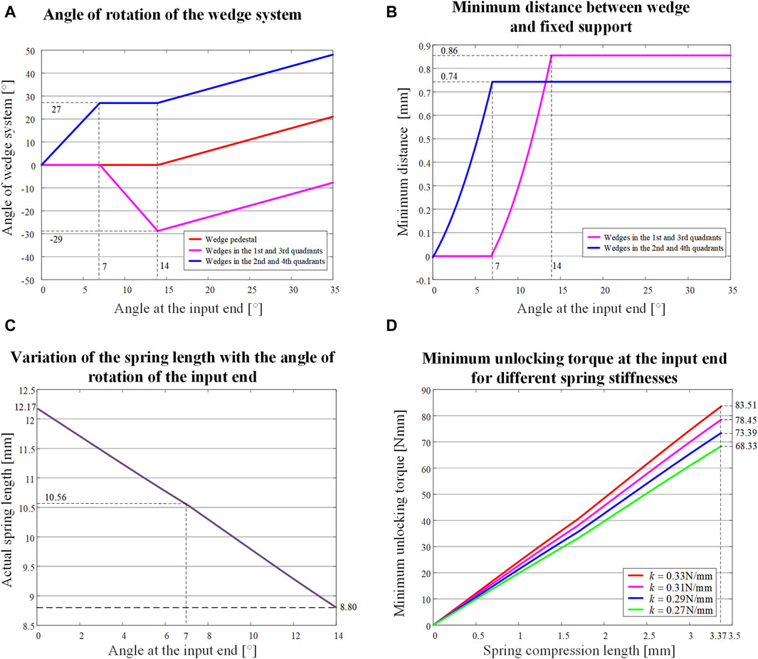
Figure 5. Variation of relevant parameters of the NBDC system with the angle of counterclockwise input. (A) Angle of the wedge and the wedge pedestal. (B) Minimum distance of the edge of the wedge from the inner wall of the fixed support. (C) Length of the spring. (D) Minimum unlocking torque of the input end with the compression length of the spring for different spring stiffnesses.
(2) When the input end drives the pin pedestal to rotate, each set of wedges will gradually detach from the inner wall of the fixed support for a certain distance, and the nearest part between the wedges and the fixed support is a section of arc, the radius of which is
The distance between the input angle
The input angle
(3) During this process, the spring would be compressed to its shortest length. Taking the wavy spring between the wedges in the 1st and 4th quadrants as an example, the positions of the connection point between the spring and the two wedges at any time are shown in Eq. 8:
where the distance from the connection point of the top of the wavy spring to the center of rotation of the wedge is
The relationship of the input angel
In the phase after Figure 3C, the pins no longer move with respect to the wedges, and the wedges no longer continue to rotate with respect to its own axis. The wedge pedestal at the output end follows the pin pedestal at the input end by the same angle
2.2 Static analysis
The main function of the NBDC is to always remain locked when the load on the output end changes and to be able to unlock smoothly when power is supplied from the input end. In order to ensure the proper functioning of the mechanism, it is necessary to carry out force analysis for two different force conditions, which are torque
2.2.1 Unlocking status analysis
Taking the counterclockwise input as an example, the initial state is the self-locking state shown in Figure 3A. When the system is subjected to counterclockwise input torque
The center of the pin
i.e.,
The spring between the two wedges
Since the unlocking of the mechanism needs to keep the 4th quadrant wedge moving counterclockwise around the point
Substituting Eq. 10 into Eq. 13 yields Eq. 14:
Define the angle between
Substituting Eq. 15 into Eq. 14 yields Eq. 16:
Due to
The minimum unlocking torque at the input for the process from Figures 3A, B can be calculated as
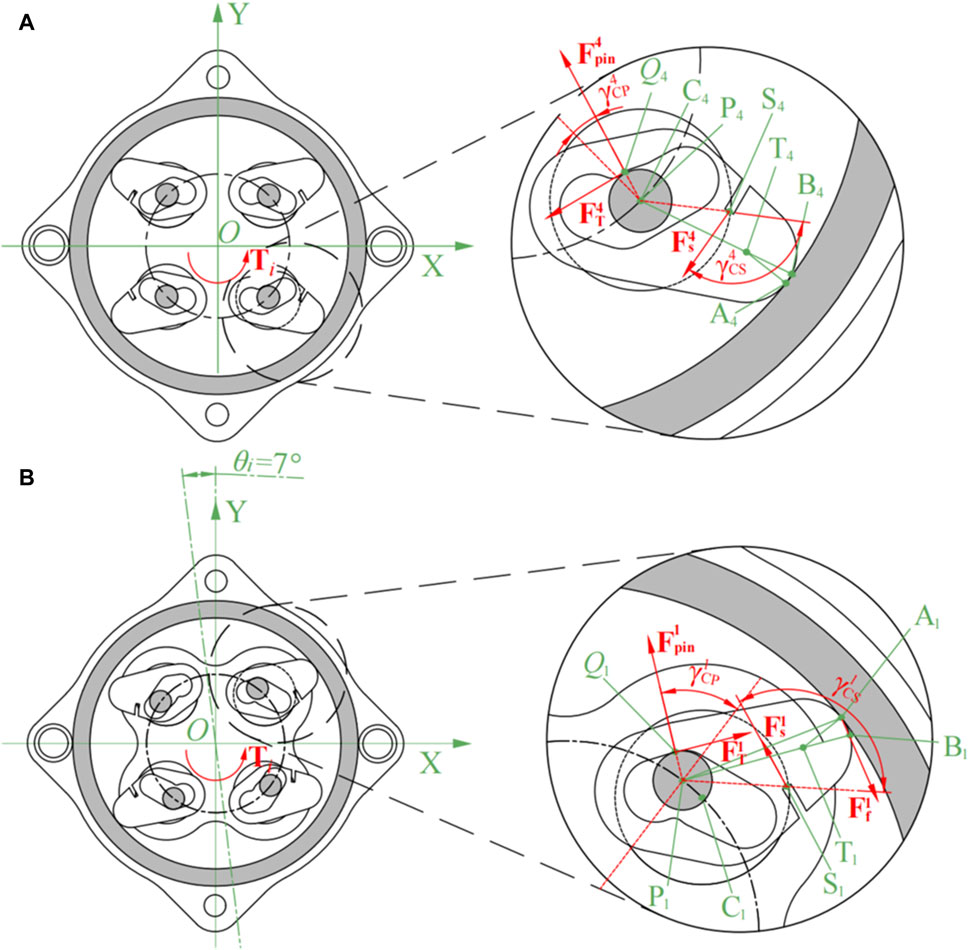
Figure 6. Mechanical analysis of the unlocking process (spring not drawn). (A) The initial counterclockwise rotate. (B) The input rotated 7° counterclockwise.
When the input is in the intermediate state of counterclockwise unlocking, the pins in the 1st and 3rd quadrants are just touching the inner wall of the wedge grooves. At this point, the pins exert positive pressure on the inner wall only in the 1st and 3rd quadrants
Owing to Eq. 19:
Substituting Eq. 19 into Eq. 18 yields Eq. 20:
Due to
For smooth unlocking, the input torque should be at least
After the aforementioned process, the pin pedestal continues to rotate counterclockwise by 7° as shown from Figures 3B, C, and the static analysis is shown in Figure 6B. In order to investigate the influence of the thickness and material on the stiffness of wavy spring, simulations were carried out using hydrostatic simulation software. The specific analytical settings for the wavy spring’s thickness was 0.1 mm, and the material was 301 stainless steels. The horizontal direction was set to be the Z-axis. In Figure 7A, the right end of the wavy spring was fixed and a compression force of 0.5 N was applied to the left end of the wavy spring. In Figures 7A, B pulling force of 0.5 N was applied to the left end of the wavy spring with the right end fixed. It can be seen from Figures 7A, B that the wavy spring was both deformed by 1.6444 mm under the load of 0.5 N in either direction. To better convey the idea, the simplified the model in these two cases are shown in Figures 7C, D.
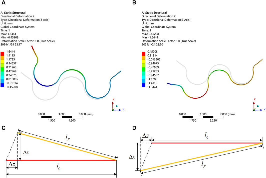
Figure 7. Static simulation of wavy spring in compression and tension. (A) Compression displacement of spring in Z-direction. (B) Tension displacement of spring in Z-direction. (C) Compression variation of spring in Z-direction. (D) Tension variation of spring in Z-direction.
The stiffness of the spring is calculated with Eq. 23:
Substituting Eq. 22 into Eq. 23 yields Eq. 24:
When considering the spring manufacturing accuracy, the stiffness variation range is taken as 0.270–0.330 N/mm, the variation of the minimum unlocking torque of the system with the compression length of the spring is shown in Figure 5D. For smooth unlocking, the minimum unlocking torque should be around 65–85 Nmm.
2.2.2 Self-locking status analysis
When the input torque is less than the critical starting torque
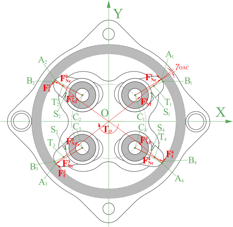
Figure 8. Static analysis of the system with counterclockwise loading torque at the output end under self-locking stage (spring not drawn).
Since the wedge pedestal provide the rotational torque through the flange bearings, the forces acting on each of the four wedges are
At this point, friction
It can be seen that when the coefficient of friction between the wedge and the inner wall of the fixed support meets the requirements, regardless of the torque applied in any direction at the output end, it will cause instant self-locking. However, when the load torque is too large, causing excessive deformation of the curved surface at the top of the wedge, i.e.,
2.3 Transient dynamic simulations and analysis
In order to verify the accuracy of the above theoretical analysis, simulation work was also carried out. The platform was Workbench of ANSYS 2020R2, with the transient dynamics analysis module. The transient dynamics model can effectively analyze the impact of external shocks on the system. On the one hand, it can be verified whether the system can be unlocked when the input end is rotated in the self-locking state. On the other hand, the system self-locking performance of the output end under load can be verified. To reduce the complexity of the iteration without affecting the simulation results, the spring force was simplified to be the maximum force at the compression extreme. This is because the minimum unlocking moment of the system depends on the stiffness
In order to verify the unlocking performance of the input end, the displacement and stress of the wedge when rotating by 7° and 14° in counterclockwise and clockwise were investigated, respectively. Figures 9A, E describe the counterclockwise and clockwise unlocking intermediate states (rotate by 7°) respectively, and the corresponding stress values are shown in Figures 9B, F. The stress maxima are basically the same, which are all lower than 50 MPa, within the nominal value of 7,075 aluminum alloy. The simulation results are consistent with the design in Figures 3B, D. Similarly, Figures 9C, G are the displacement for 14° counterclockwise and clockwise rotations of the input, and their corresponding stress diagrams are in Figures 9D, H, which is also in accordance with Figures 3C, E.
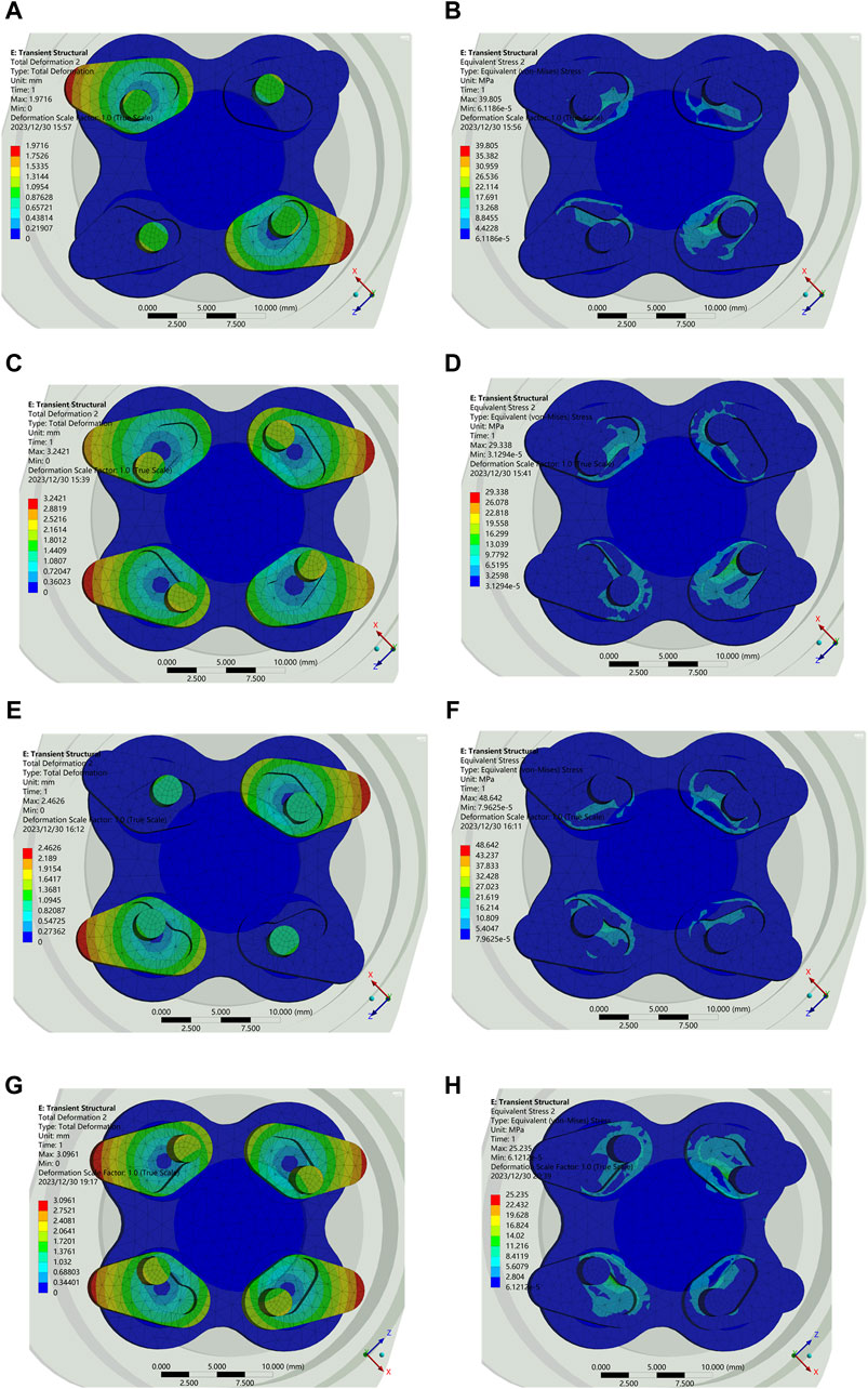
Figure 9. Displacement and stress. (A) Displacement at 7° counterclockwise. (B) Stress at 7° counterclockwise. (C) Displacement at 14° counterclockwise. (D) Stress at 14° counterclockwise. (E) Displacement at 7° clockwise. (F) Stress at 7° clockwise. (G) Displacement at 14° clockwise. (H) Stress at 14° clockwise.
In order to verify the self-locking performance of the output end, the arc surface strain at the top of the wedge is set to be
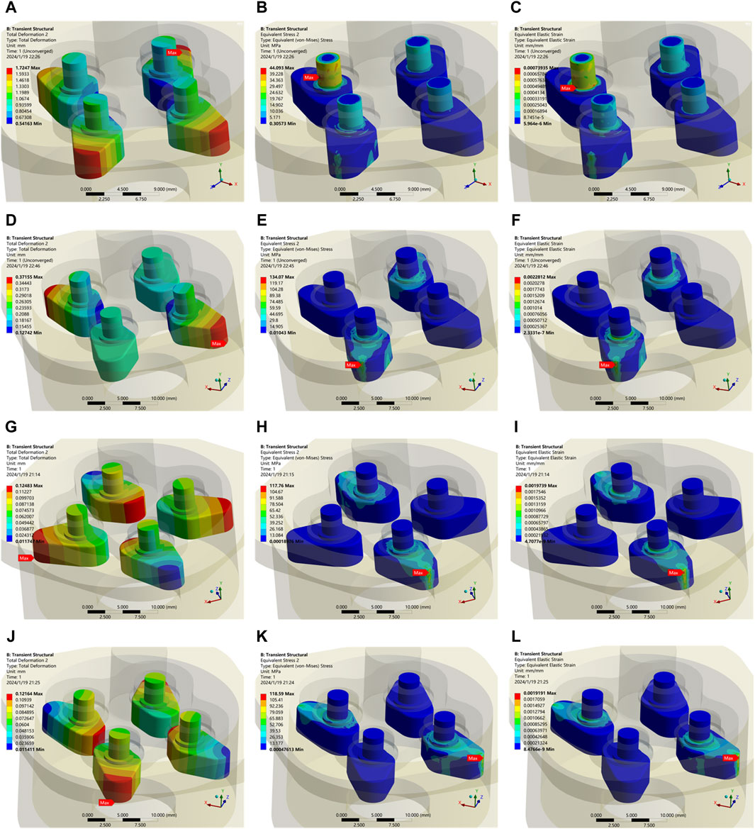
Figure 10. Transient dynamic analysis of the output end with applied load. (A) Self-locking failure with displacement of the wedge. (B) Stress in the wedge in self-locking failure. (C) Strain in the wedge in self-locking failure. (D) Displacement of the wedge in the state under
For further investigation, the range of
The maximum stress and strain at the top of the wedge for different values of
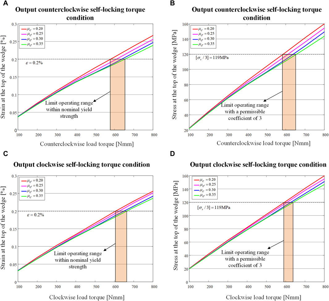
Figure 11. Maximum stress and maximum strain at the top of the wedge when load torque is applied to the output end for different values of
The overall trend is that as
By drawing a boundary line
3 Experimental analysis of NBDC
According to the previous analysis, a 3D model was established, and a prototype was assembled. The pin pedestal, wedge pedestal, wedges and fixed support are made of aluminum alloy (7,075 series), wavy springs were customized (stainless steel, 301 series, stiffness is around 0.30 N/mm), the four pins were selected as standard parts (stainless steel, 304 series,
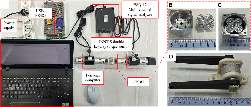
Figure 12. NBDC torque test experimental setup. (A) Experimental setup. (B) NBDC components. (C) Assembled NBDC. (D) NBDC unlocking test.
The NBDC was positioned between two JNNT-S dual keyway torque transducers to test the unlocking torque from the input end and the maximum self-locking torque from the output end, which are shown in Figure 12A. The system configuration is as follows:
(1) The input end and output end were connected to the connecting flange through tightening screws, and then connected to the JNNT-S double keyway torque transducers through an elastic coupling (static torque transducer, movement range of 0°–180°, torque range of 0–20 Nm).
(2) JNNT-S double keyway torque transducer were connected to BSQ-12 multi-channel signal analyzer which connected to a computer via USB-RS485, outputting the synchronous torque of two transducers.
(3) Elastic coupling could eliminate the axis deviation of the overall transmission system, the transmission efficiency is 98%, which was negligible.
(4) By fixing the output end coupling, bidirectional torque could be transmitted to the input end, and the unlocking torque would be obtained through numerical analysis of the two sensors.
(5) By fixing the input end coupling, bidirectional torque could be exerted on the output end, and the maximum self-locking torque would be obtained through numerical analysis of the two sensors.
In order to test the bidirectional unlocking idle angle, a 10 cm long rocker was installed at the input end and the output end respectively to facilitate the experiment. The WT901164K angle sensors (sampling frequency is 2000 Hz) were placed at the center of the shafts to capture the angle changes of the two ports simultaneously, as shown in Figure 12D.
By applying torque to the input and output ends respectively, the corresponding response was recorded by the torque sensor. As shown in Figure 13A, when the input end is unlocked, the output torque lags the input torque change and the difference is within 80 Nmm. This value is the unlock torque of the system, which is basically the same as the theoretical value in Figure 5D. From the results of transient dynamics, the self-locking torque of the system during normal operation is about 600 Nmm. When the load applied to the output is 600 Nmm, as shown Figure 13B, there is barely no torque response from the input end (less than 40 Nmm in both directions), which is consistent with the finite element simulation. The reason for the torque fluctuation at the input end is when the diagonal wedge self-locks, the other diagonal wedge rotates a slight angle, and during the rotation, the inner wall of the wedge groove transfers part of the force to the corresponding pin. The force is further transmitted to the torque sensor through the pin pedestal. This small torque will not cause back-driving phenomena at the input end. By rotating the rocker in both directions at the input end, it can be seen that the angular response of the output end is shifted by 14°, as shown in Figure 13C, which is consistent with design of the idle angle.
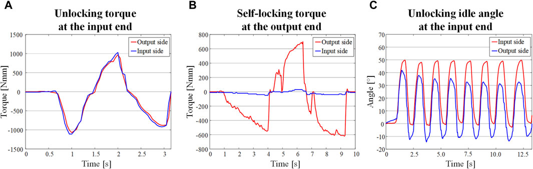
Figure 13. Unlocking and self-locking experiments of the NBDC. (A) Bidirectional unlocking torque change at the input end. (B) Self-locking torque change at the output end. (C) Unlocking idle angle at the input end.
4 Applications with NBDC embedded in a prosthetic wrist
To better demonstrate how the proposed component could be used in practical applications, a prosthetic wrist with rotation function was built, integrating the proposed NBDC. There are three reasons for the chosen of the application scenario: (1) The rotational degree of freedom of the wrist is mostly used in practice (Seo et al., 2017). (2) The rotation of the wrist is prone to stay unchanged once reach the target angle (Neumann, 2016). (3) The physiological rotational movement of the human wrist comes from the rotation of the radius around the ulna, and the actual rotational movement occurs near the elbow joint. If the amputation was executed near the hand, the amputee would still retain some rotational function of the forearm and does not need a rotationally functional prosthetic wrist. Thus, the prosthetic wrist module with rotational freedom is suitable for amputees with amputations close to the elbow, providing ample space for the implementation of the prosthesis. Figure 14 illustrates the application scenario where the proposed locking component was integrated to a prosthetic wrist. The prosthetic wrist was attached to the amputee through a prosthetic socket, and the constituent components of the prosthesis from the socket to the hand were the driving motor, the self-locking component and the harmonic reducer respectively. The integrating of the proposed locking component would allow the transmission of the rotational motion of the motor to the load transparently, while the time-varying torque generated at the load side would be prevented from transmitting back by this component, which ensures the stability of the prosthetic joint and reduces the power consumption. The component, with a diameter of 33 mm and a length of 15 mm, weighting 25.5 g, could theoretically be integrated in series to any forearm joint except the hand without compromising the total weight and dimension, and thus has the potential to be widely used in prosthetic rotary joints.
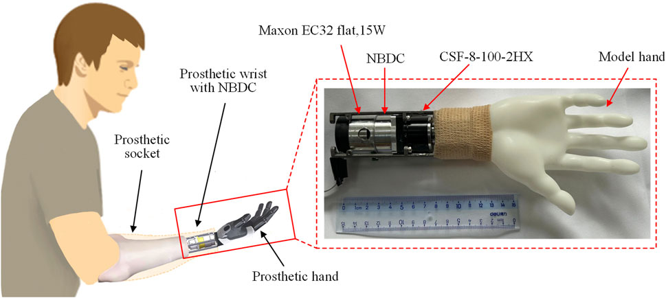
Figure 14. Schematic of the specific application of the NBDC mechanism to the prosthetic wrist.
Figure 15A illustrates the self-locking performance experiments of NBDC in a prosthetic wrist system, where the self-locking ability of the wrist joint was tested with and without NBDC, respectively, and the results are shown in Figure 15B. Since the harmonic reducer itself has certain self-locking capacity, the upper limit of the self-locking capacity of without the embedded NBDC component is 750 Nmm. By contrast, the self-locking capacity with the NBDC reaches 3560 Nmm in this experiment. It is worth pointing out that 3560 Nmm is not the upper limit of the system with the NBDC, but a safe experimental limit set to protect the harmonic reducer. From the calculation and analysis in Section 3, it can be seen that the theoretical upper limit could reach 600
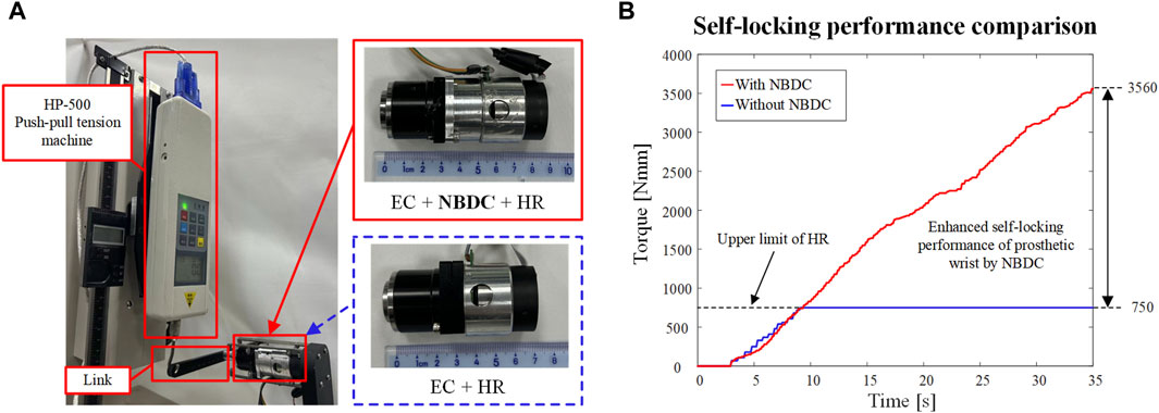
Figure 15. Experimental self-locking performance of NBDC in prosthetic wrist system. (A) The self-locking performance of the prosthetic wrist with and without the NBDC mechanism was tested separately. (B) Self-locking performance comparison.
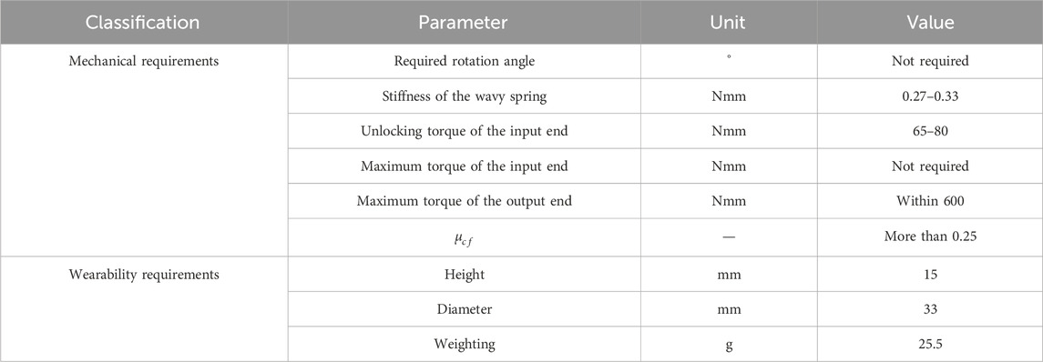
Table 1. Mechanical requirements and wearability requirements for the NBDC mechanism.
5 Discussion
This paper designed a new type of NBDC mechanism, theoretically analyzed the self-locking conditions of the model and the influence of different friction coefficients on the self-locking performance, revealed that the friction coefficient
6 Conclusion
In this paper, a novel NBDC is proposed, which can be applied in the forearm rotary motion joints of prosthetic wrists. It may save power to a certain extent under the premise of guaranteeing the safety and stability of manipulations. Detailed kinematic, static and transient dynamic analysis were carried out, and a prototype of the proposed design was assembled and tested to verify its self-locking and unlocking performance. Experimental results showed that the bidirectional self-locking torque of this NBDC for external load is about 600 Nmm, and the unlocking torque at the input end is about 80 Nmm. It is worth pointing out that connecting a reducer in series between the output end and the load can further expand the self-locking performance of the mechanism, thereby expanding its application scenarios.
Data availability statement
The original contributions presented in the study are included in the article/Supplementary material, further inquiries can be directed to the corresponding author.
Author contributions
YLi: Data curation, Formal Analysis, Investigation, Methodology, Project administration, Software, Writing–original draft, Writing–review and editing, Conceptualization, Validation. YLu: Formal Analysis, Investigation, Methodology, Project administration, Writing–original draft, Writing–review and editing, Data curation, Software, Validation. TX: Formal Analysis, Project administration, Supervision, Writing–original draft, Writing–review and editing. JL: Conceptualization, Formal Analysis, Methodology, Project administration, Writing–original draft, Writing–review and editing, Funding acquisition, Investigation, Resources, Supervision, Visualization.
Funding
The author(s) declare that financial support was received for the research, authorship, and/or publication of this article. This research was funded by the National Key R&D Program of China (2020YFC2007800) granted to Huazhong University of Science and Technology, and the National Natural Science Foundation of China (52005191 and 52027806).
Conflict of interest
The authors declare that the research was conducted in the absence of any commercial or financial relationships that could be construed as a potential conflict of interest.
Publisher’s note
All claims expressed in this article are solely those of the authors and do not necessarily represent those of their affiliated organizations, or those of the publisher, the editors and the reviewers. Any product that may be evaluated in this article, or claim that may be made by its manufacturer, is not guaranteed or endorsed by the publisher.
References
Ann, N. K., Lin, W., and Ng, L. E. (2000). A new linear piezoelectric motor with self-lock feature. Jpn. J. Appl. Phys. 39, 1311–1313. doi:10.1143/jjap.39.l1311
Bajaj, N. M., Spiers, A. J., and Dollar, A. M. (2019). State of the art in artificial wrists: a review of prosthetic and robotic wrist design. IEEE Trans. Robot. 35, 261–277. doi:10.1109/tro.2018.2865890
Bandara, D. S. V., Gopura, R., Hemapala, K., and Kiguchi, K. (2014). “A multi-DoF anthropomorphic transradial prosthetic arm,” in 5th IEEE RAS/EMBS international conference on biomedical robotics and biomechatronics, 1039–1044. doi:10.1109/biorob.2014.6913917
Biddiss, E., Beaton, D., and Chau, T. (2007). Consumer design priorities for upper limb prosthetics. Disabil. Rehabil. Assist. Technol. 2, 346–357. doi:10.1080/17483100701714733
Billones, R. K. C., Lim, J. M., Cardenas, R., Manguerra, M. V., Vicerra, R. R. P., Bugtai, N. T., et al. (2020). “Prototyping a prosthetic arm for ulnar and radial deviation,” in 2020 IEEE 12th international conference on humanoid, nanotechnology, information Technology, communication and control, environment, and management (HNICEM), 1–6. doi:10.1109/hnicem51456.2020.9400108
Chu, J.-U., Jung, D.-H., and Lee, Y.-J. (2008). “Design and control of a multifunction myoelectric hand with new adaptive grasping and self-locking mechanisms,” in 2008 IEEE International conference on robotics and automation, 743–748. doi:10.1109/robot.2008.4543294
Cipriani, C., Controzzi, M., and Carrozza, M. C. (2010). Objectives, criteria and methods for the design of the SmartHand transradial prosthesis. Robotica 28, 919–927. doi:10.1017/S0263574709990750
Cirelli, M., Giannini, O., Cera, M., Simoni, F.De, Valentini, P. P., and Pennestri, E. (2021). The mechanical efficiency of the Rzeppa transmission joint. Mech. Mach. THEORY 164, 104418. doi:10.1016/j.mechmachtheory.2021.104418
Controzzi, M., Bassi Luciani, L., and Montagnani, F. (2017). Unified approach to bi-directional non-back drivable roller clutch design. Mech. Mach. Theory 116, 433–450. doi:10.1016/j.mechmachtheory.2017.06.010
Controzzi, M., Cipriani, C., and Carrozza, M. C. (2010). Miniaturized non-back-drivable mechanism for robotic applications. Mech. Mach. Theory 45, 1395–1406. doi:10.1016/j.mechmachtheory.2010.05.008
Deijs, M., Bongers, R. M., Ringeling-van Leusen, N. D. M., and Van Der Sluis, C. K. (2016). Flexible and static wrist units in upper limb prosthesis users: functionality scores, user satisfaction and compensatory movements. J. Neuroeng. Rehabil. 13, 1–13. doi:10.1186/s12984-016-0130-0
Ding, H., Shi, Z., Hu, Y., Li, J., Yu, B., and Zhang, P. (2021). Lightweight design optimization for legs of bipedal humanoid robot. Struct. Multidiscip. Optim. 64, 2749–2762. doi:10.1007/s00158-021-02968-2
Gao, X., Zhang, S., Deng, J., and Liu, Y. (2021). Development of a small two-dimensional robotic spherical joint using a bonded-type piezoelectric actuator. IEEE Trans. Ind. Electron. 68, 724–733. doi:10.1109/TIE.2019.2959475
Guo, X.-Y., Li, W.-B., Gao, Q.-H., Yan, H., Fei, Y.-Q., and Zhang, W.-M. (2020). Self-locking mechanism for variable stiffness rigid-soft gripper. SMART Mater. Struct. 29, 035033. doi:10.1088/1361-665X/ab710f
He, B., Zhang, C., Cao, X., Li, G., and Xiong, X. (2023). An approach to recognizing the working cycle stage with small sample data for energy conservation. J. Clean. Prod. 414, 137771. doi:10.1016/j.jclepro.2023.137771
Hu, Q., Bai, Y., He, L., Cai, Q., Tang, S., Ma, G., et al. (2020). Intelligent framework for worker-machine safety assessment. J. Constr. Eng. Manag. 146. doi:10.1061/(ASCE)CO.1943-7862.0001801
Hu, Q., Huang, H., Dong, E., and Sun, D. (2021). A bioinspired composite finger with self-locking joints. IEEE Robot. Autom. Lett. 6, 1391–1398. doi:10.1109/LRA.2021.3056345
Kang, J., Seo, K., and Kim, K. (2015). Experimental investigation of friction noise in lead screw system under mode-coupling. J. Mech. Sci. Technol. 29, 5183–5188. doi:10.1007/s12206-015-1118-6
Karbalaei Akbari, M., Baharvandi, H. R., and Mirzaee, O. (2013). Fabrication of nano-sized Al2O3 reinforced casting aluminum composite focusing on preparation process of reinforcement powders and evaluation of its properties. Compos. Part B Eng. 55, 426–432. doi:10.1016/j.compositesb.2013.07.008
Kimura, A., Omura, L., Yoshioka, S., and Fukashiro, S. (2021). Identifying coordination between joint movements during a throwing task with multiple degrees of freedom. Hum. Mov. Sci. 77, 102799. doi:10.1016/j.humov.2021.102799
Lee, G., Hong, G. Y., and Choi, Y. (2021). Tendon-driven compliant prosthetic wrist consisting of three rows based on the concept of tensegrity structure. IEEE Robot. Autom. Lett. 6, 3956–3963. doi:10.1109/lra.2021.3067237
Liu, C., Tosun, T., and Yim, M. (2021). A low-cost, highly customizable solution for position estimation in modular robots. J. Mech. Robot. ASME 13. doi:10.1115/1.4050249
Liu, X.-F., Zhang, X.-Y., Cai, G.-P., and Chen, W.-J. (2022). Capturing a space target using a flexible space robot. Appl. Sci. 12, 984. doi:10.3390/app12030984
Lu, L., Jiang, C., Hu, G., Liu, J., and Yang, B. (2021). Flexible noncontact sensing for human-machine interaction. Adv. Mater. 33, e2100218. doi:10.1002/adma.202100218
Montagnani, F., Controzzi, M., and Cipriani, C. (2015a). Is it finger or wrist dexterity that is missing in current hand prostheses? IEEE Trans. Neural Syst. Rehabil. Eng. 23, 600–609. doi:10.1109/tnsre.2015.2398112
Montagnani, F., Controzzi, M., and Cipriani, C. (2015b). Non-back-drivable rotary mechanism with intrinsic compliance for robotic thumb abduction/adduction. Adv. Robot. 29, 561–571. doi:10.1080/01691864.2014.992957
Mota, B., Faria, P., and Ramos, C. (2023). Joint production and maintenance scheduling for total cost and machine overload reduction in manufacturing: a genetic algorithm approach. IEEE ACCESS 11, 98070–98081. doi:10.1109/ACCESS.2023.3312557
Muraliraja, R., Arunachalam, R., Al-Fori, I., Al-Maharbi, M., and Piya, S. (2019). Development of alumina reinforced aluminum metal matrix composite with enhanced compressive strength through squeeze casting process. Proc. Inst. Mech. Eng. Part L J. Mater. Des. Appl. 233, 146442071880951–314. doi:10.1177/1464420718809516
Mustafa, S. K., Yang, G., Yeo, S. H., Lin, W., and Pham, C. B. (2006). “Development of a bio-inspired wrist prosthesis,” in 2006 IEEE conference on robotics (Bangkok, Thailand: IEEE), 1–6.
Neumann, D. A. (2016) Kinesiology of the musculoskeletal system-e-book: foundations for rehabilitation. Elsevier Health Sciences.
Okafor, K. C., and Longe, O. M. (2022). WearROBOT: an energy conservative wearable obstacle detection robot with LP multi-commodity graph. IEEE ACCESS 10, 105843–105865. doi:10.1109/ACCESS.2022.3211319
Semasinghe, C. L., Ranaweera, R., Prasanna, J. L. B., Kandamby, H. M., Madusanka, D. G. K., and Gopura, R. (2018). HyPro: a multi-DoF hybrid-powered transradial robotic prosthesis. J. Robot. 2018, 1–15. doi:10.1155/2018/8491073
Seo, M., Kim, H., and Choi, Y. (2017). “Human mimetic forearm mechanism towards bionic arm,” in 2017 international conference on rehabilitation robotics (ICORR), 2017, 1171–1176. doi:10.1109/ICORR.2017.8009408
Shi, Q., Gao, Z., Jia, G., Li, C., Huang, Q., Ishii, H., et al. (2021). Implementing rat-like motion for a small-sized biomimetic robot based on extraction of key movement joints. IEEE Trans. Robot. 37, 747–762. doi:10.1109/TRO.2020.3033705
Wei, T., Liu, W., Yang, W., Zeng, S., Yan, X., and Guo, J. (2023). Structural design and self-locking performance verification of the snap-fit spatial self-locking energy absorption system under the impact loading. Int. J. CRASHWORTHINESS, 1–16. doi:10.1080/13588265.2023.2253040
Wu, X., Hua, H., Zhao, C., Shi, N., and Wu, Z. (2023). A back-drivable rotational force actuator for adaptive grasping. Actuators 12, 267. doi:10.3390/act12070267
Keywords: prosthesis joint, wrist, non-back-drivable-clutch, backlash, manipulation stability, transient dynamics
Citation: Liu Y, Luo Y, Xiao T and Liang J (2024) Non-back-drivable clutch based self-locking mechanism of prosthetic joint to improve manipulation stability. Front. Bioeng. Biotechnol. 12:1385076. doi: 10.3389/fbioe.2024.1385076
Received: 11 February 2024; Accepted: 10 May 2024;
Published: 30 May 2024.
Edited by:
Wujing Cao, Chinese Academy of Sciences (CAS), ChinaReviewed by:
Wojciech Wolański, Silesian University of Technology, PolandXiangxin Li, Chinese Academy of Sciences (CAS), China
Copyright © 2024 Liu, Luo, Xiao and Liang. This is an open-access article distributed under the terms of the Creative Commons Attribution License (CC BY). The use, distribution or reproduction in other forums is permitted, provided the original author(s) and the copyright owner(s) are credited and that the original publication in this journal is cited, in accordance with accepted academic practice. No use, distribution or reproduction is permitted which does not comply with these terms.
*Correspondence: Jiejunyi Liang, jiejunyiliang@gmail.com
†These authors have contributed equally to this work and share first authorship