Review of Emerging Additive Manufacturing Technologies in 3D Printing of Cementitious Materials in the Construction Industry
 Pshtiwan Shakor
 Shami Nejadi1
  Sardar Malek
- 1Centre for Built Infrastructure Research, Faculty of Engineering and Information Technology, School of Civil and Environmental, University of Technology Sydney, Ultimo, NSW, Australia
- 2Centre for Autonomous Systems, Faculty of Engineering and Information Technology, School of Electrical, Mechanical and Mechatronics, University of Technology Sydney, Ultimo, NSW, Australia
Additive manufacturing is a fabrication technology that is rapidly revolutionizing the manufacturing and construction sectors. In this paper, a review of various prototyping technologies for printing cementitious materials and selected 3D printing techniques are presented in detail. Benchmark examples are provided to compare three well-known printing techniques; inkjet printing (binder jetting), selected laser sintering (SLS), and extrusion printing (extrusion based process). A comprehensive search in the literature was conducted to identify various mix designs that could be employed when printing cementitious materials. Aspects of concrete mix design are described, and some new experiments are conducted to analyse the printability of new mixes by the authors. Future research in the area of the rheology of cementitious materials and its relationship with the structural performance of finished concretes are highlighted.
Introduction
Construction companies face numerous and substantial challenges regarding the costs of production. For instance, cast in-situ concrete processes produce many waste materials that are discarded afterwards, particularly if formwork is not used again. In contrast, recyclable scaffold reduces waste. However, such molds are relatively expensive to produce, and the long series of scaffolding is needed to make these molds cost-effective (De Witte, 2015). The life cycle of scaffolds is another issue in terms of the environmental footprint of scaffolds, particularly considering greenhouse gas emissions. This, in turn, causes much repetition thus enabling better fabrication, precise production of elements, and prints of any geometries, which are hard to make for conventional application such as façade elements (Buswell et al., 2007; Lim et al., 2012).
It has been shown that rapid prototype technologies (e.g., 3D printing) could completely revolutionize a range of production methods (Lipson and Kurman, 2013). The main advantage of rapid prototype technologies is directly constructing parts in one step from the CAD data (Vaezi and Chua, 2011). For instance, the use of 3D printing could reduce 35–60% of the total cost of concrete construction simply by removing the need for formwork (Lloret et al., 2015).
There are issues with using molds for construction such as their recyclability and scaffold size limitations for a range of structural components. Many freeform components are cast in-situ, where their quality cannot be controlled (Elhag et al., 2008). For that reason, high-performance components (e.g., beam and columns) are made in controlled environments. Various 3D techniques are being used in Additive Manufacturing (AM) processes, such as 3D scanning in the digital fabrication process and for file generation (Ma et al., 2017).
Over-ordering of concrete (Tam et al., 2006) and tied up formwork (Cole, 1998) are the main contributors to extra CO2 emissions of in-situ concrete casting and a huge waste of materials. Next, hardening of concrete produces CO2. Thus, the development of new and innovative construction methods is motivated by the pursuit of economic, environmentally-friendly, and architectural benefits. Bos et al. (2016) believed that using 3DP technology is a decent introductory step toward replacing cement in the construction industry with less energy-intensive materials such as fly ash and geopolymer concrete.
There are some issues and limitations associated with 3D printing such as the low stiffness and strength of the printed building materials as well as the printing size (Edwards et al. (2013). Bos et al. (2016) mentioned that the WinSun company could print a large building component (~36.6 × 12.2 × 6.1 m) with their 3D printer and an automated robotic arm. Also, Weger et al. (2016) reported printing structural components with cross-sections up to 6 × 6 m using a D-shape printer by pouring liquid on the powder-based materials. Another limitation is that the intended printed size does not match with the specifications of all kinds of 3D printers, as each printer has its own specifications for fabricating structural elements. There are also concerns regarding powder-based 3D printing methods, namely, the need for support to hold the weight of the printed object until the material gains enough strength. Additionally, mix design and using coarse aggregates is another challenge for 3D printing of concrete. For instance, the WinSun company used only fine cementitious materials without coarse aggregate in their 3D printing application.
This study presents an overview of the available and trending techniques for printing or plotting cementitious materials and their adaptions to different mix ingredients and the mixing process.
Overview of Rapid Prototype Technologies in the Construction Industry
According to Tay et al. (2016), rapid prototyping in the building and construction field was introduced as an innovative approach to constructing structures (Pegna, 1997). Since then, rapid prototyping and later digital fabrication have gained popularity in the construction industry as well as many others such as automotive, aerospace, and biomedical (see Buswell et al., 2007; Berman, 2012). Feng et al. (2015a) classified rapid prototyping (RP) technologies into three main categories: additive, additive/subtractive and subtractive as shown in Figure 1.
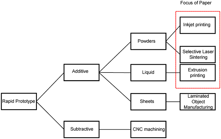
Figure 1. Overview of rapid prototyping technologies and the techniques discussed in this paper. The box highlights the techniques employed in this paper.
In subtractive manufacturing, a 3D object is created by removing the material from a block using material-cutting machines. In additive manufacturing which is the focus of this paper, a feed material in the form of powder, liquid, filament, glue, or binder is added to a substrate, layer by layer, to construct a 3D object. The amount of leftover materials from this process is often considerably larger than the outcome of the additive manufacturing process when creating the same 3D object (Ambrosi and Pumera, 2016).
Li et al. (2016) reviewed additive manufacturing technologies and 3D printing with various raw materials in the market. They found that photopolymers had the largest share of the 3D printing market (56% by weight), followed by thermoplastics (42%), metals (only 1%). The market share of ceramics, concrete materials was about 1% in total.
In this paper, we discuss the key additive manufacturing techniques that have the potential to be used in the construction industry.
Inkjet Printing (Binder Jetting)
The inkjet printing, also known as binder jetting, is one of the common printing methods used to 3D print parts in various industries and it has great potentials for constructing large structures from cementitious materials. In this method, a thin layer of the printing material, often in powder form but sometimes in chip form, is spread (e.g., with a roller) over a solid platform or tray. Then, a liquid binder is deposited over the powder bed as shown in Figure 2. The binder glues the powder together to form a solid part. This process is repeated several times and layers are printed on top of each other to form a 3D object. It should be noted that some printing materials may require curing (Wu et al., 2016) or kiln firing (Withell et al., 2011) in the oven as an additional post-processing step. This would make inkjet printing an energy-intensive technique for creating large structures. One of the main roles of the powder is to support the part while the binder is being deposited over the top layer that was printed in the previous step (Tay et al., 2017). Although complex geometries may be printed with this technique, the finished part often contains voids which deteriorate the part's quality. Inkjet printing is more suitable for printing parts and structures in which high printing speed is preferred over the printing accuracy according to Wu et al. (2016). Researchers have reported employing various combinations of powder and binder. For instance, Feng et al. (2015b) employed plaster and water as powder and binder, respectively. Withell et al. used a water-based liquid to bind clay particles while Henke and Treml (2012) tried binding wood chips (particles) with a mixture of water, cellulose, and cement (binder). Gibbons et al. (2010) used rapid hardening Portland cement with polyvinyl alcohol binder to print cement-based structures. Additional procedures after the printing process (post-processing step) are often applied to the printed part as listed in Table 1.
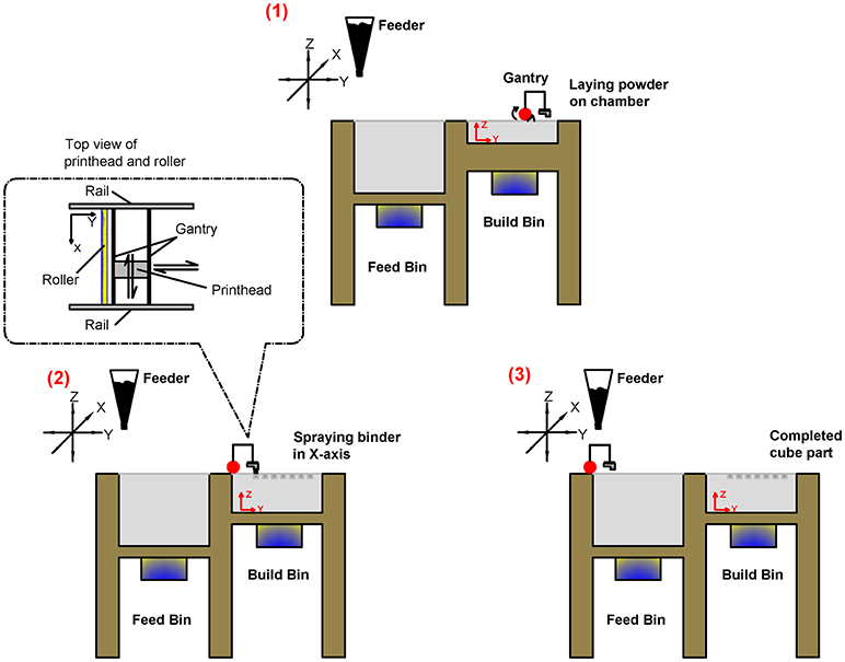
Figure 2. Schematic illustration of the inkjet 3D printing process.
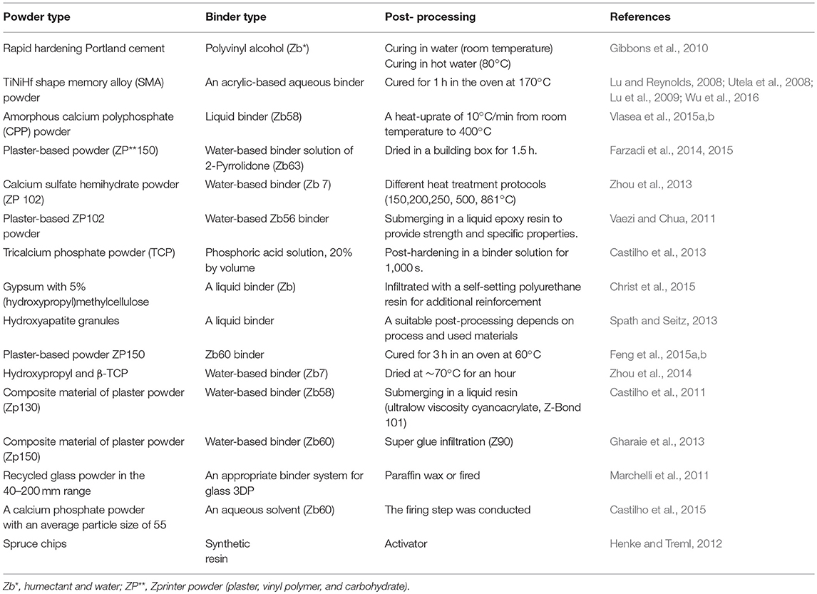
Table 1. Types of powder, binder, and post-processing for the Inkjet Printing.
Selective Laser Sintering (SLS)
Selective Laser Sintering (SLS) is the process of sintering powders layer-by-layer (Kruth et al., 2005). The selected areas on the powder bed are exposed to the thermal energy of a laser beam. This technology was introduced in 1986 by Carl Deckard and Joe Beaman at the University of Texas according to Lipson and Kurman (2013). Cañete Vela (2014) claimed that laser sintering can be used to make metallic and polymeric objects. The technique is similar to the one used in Stereolithography (SLA), in which a photo-solidification process is initiated by light to create a chain of interconnected molecules.
In the SLS, a jet of CO2 is used as a laser light which strikes the light on the powders. The powders could be different material powders such as alloys, ceramics, cermet, nylon, glass composite, metal, steel, and carbonate (Jeng et al., 2000). Figure 3 schematically shows how the laser is employed to melt the powder or slurry. The molten materials become a liquid formation and solidify completely when the temperature is reduced (Kolossov et al., 2004). Computational modeling has been used in some studies to better understand the SLS process (Kumar, 2003). Peter and Jean-Pierre (2006) examined the residual stresses in selective laser sintering (SLS) and selective laser melting (SLM), aiming to a better understanding of the sintering phenomenon. The neat powder properties of various SLS powders were found to affect the fabrication process and ultimately lead to improving the mechanical properties of the resultant components (Dalgarno and Stewart, 2001). Similar to inkjet printed parts, SLS parts usually need a post-processing step which could influence the structural performance of the finished part. Therefore, post-processing and knowledge of the sintering phenomena must be integrated into the design and planning process to obtain a 3D printed part with optimum quality (Ian and Dongping, 1997).
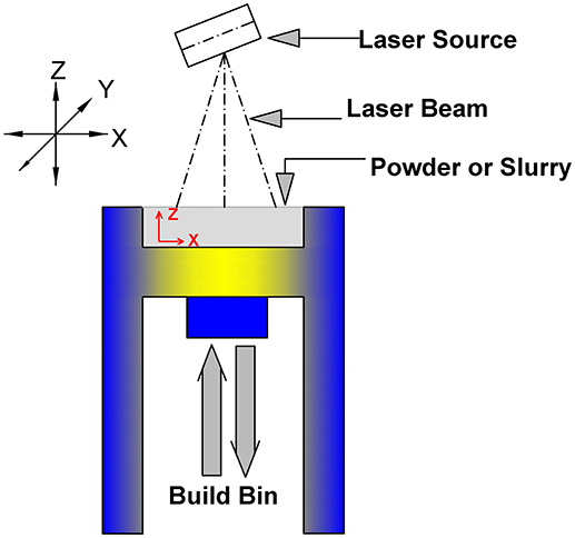
Figure 3. Selective Laser Sintering diagram.
An investigation by Dalgarno and Stewart (2001) reported the outcomes of a design study into production tools used in an industrial SLS process. The abovementioned both studies evaluate the improved productivity arising from the use of conformal cooling channels and also examines tool wear.
Extrusion Printing (Extrusion Based Process)
The extrusion printing technique fabricates three-dimensional objects from a computer-generated model as in a typical rapid prototype process. Detailed models may be derived from computed tomography scans, magnetic resonance imaging scans or model data created from 3D object digitizing systems and employed in this technique. In the Fused Deposition Modeling (FDM) technique, a thermoplastic filament material is extruded and deposited as a semi-molten polymer onto a platform in a layer-by-layer cycle. Figure 4 shows how each layer is created; the platform base is lowered and the next layer is stacked atop another as prescribed by the computer model (Zein et al., 2002). The 3D plotting/printing of concrete through extrusion was based on the FDM process. The initial idea of the extrusion printing for construction elements was offered in the late 1990s by Pegna (1997). Later, this technique was utilized at the University of Southern California (USC) with some adjustments and modifications. The process was called contour crafting by Khoshnevis and Dutton (1998) and Hwang and Khoshnevis (2004). Delgado Camacho et al. (2018) claimed that employing novel 3DP techniques (mainly extrusion) in the construction industry could reduce the labor costs, decrease material waste, and make complex geometries, which are difficult to attain using conventional construction techniques. Moreover, Lloret et al. (2015) aimed to link all the digital design, additive manufacturing, and material properties to build a complex shape from concrete structures.
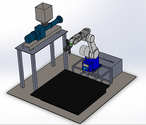
Figure 4. Graphical explanation of extrusion printing using 6 DOF robot with a progressive cavity pump.
Lim et al. (2012) presented the application of large-scale printed concrete via additive manufacturing processes which are called Concrete Printing. The extruded mortar slurry and several new criteria have been discussed, such as mix design of mortar and delivery system that has been developed for the printed process. Table 2 explains the three main techniques of the additive manufacturing for the construction applications.
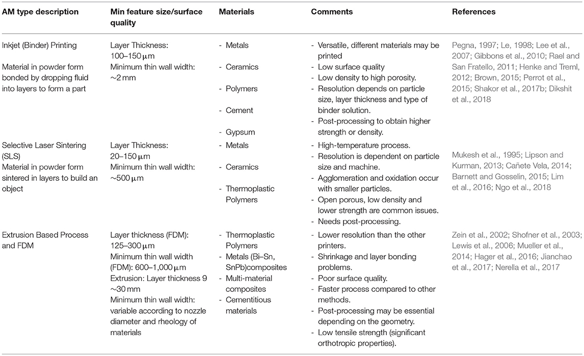
Table 2. Comparison of additive manufacturing technologies in the construction field.
The properties of different concrete mix designs and the various ingredients have been reviewed with the appropriate rheology in wet concrete as well as the viscosity ratio for the dimensional stability (Zijl et al., 2016).
Ashraf et al. (2018) focused on the metallic 3D printed structures and studied the micro-lattice printing structures from stainless steel and titanium.
Those paths and steps are vital to building an object when the additive manufacturing process involves a controllable machine such as a robot as shown in Figure 4.
Concrete Mix Design
The concrete mix design plays a major role in both the 3D printing process of cementitious concrete and the structural performance of the printed concrete elements. When 3D printing materials, the fresh concrete or mortar are built one layer atop another while, the lower layers hold the layers above them. Although rapid prototype technologies and 3D printing techniques have been reviewed in the literature quite extensively, only a few studies investigated the role of concrete mix designs in the 3D printing of cementitious materials. Some recent studies focused on different proportions of chemical admixtures and water/cement ratios, while earlier ones Jeon et al. (2013) attempted to use less coarse aggregate. It is extremely difficult to pass coarse aggregates through the pump and small nozzle. Furthermore, layers with coarse aggregates could not hold the original shape of the printed layers.
Le et al. (2012a) prepared the concrete mixes for the print 3D fiber-reinforced concrete with the fine aggregates. The aim of the experimental studies was to investigate the extrudability and buildability for the concrete mixes. The diameter for the nozzle delivery systems is 9 mm to give a high printed resolution. Table 3 summarized the mix proportion of the concrete. In their study, they addressed the shear strength for the workability of concrete and the compressive strength for the printed specimens. The optimum compressive strength that has been achieved when curing for 28 days was 110 MPa.
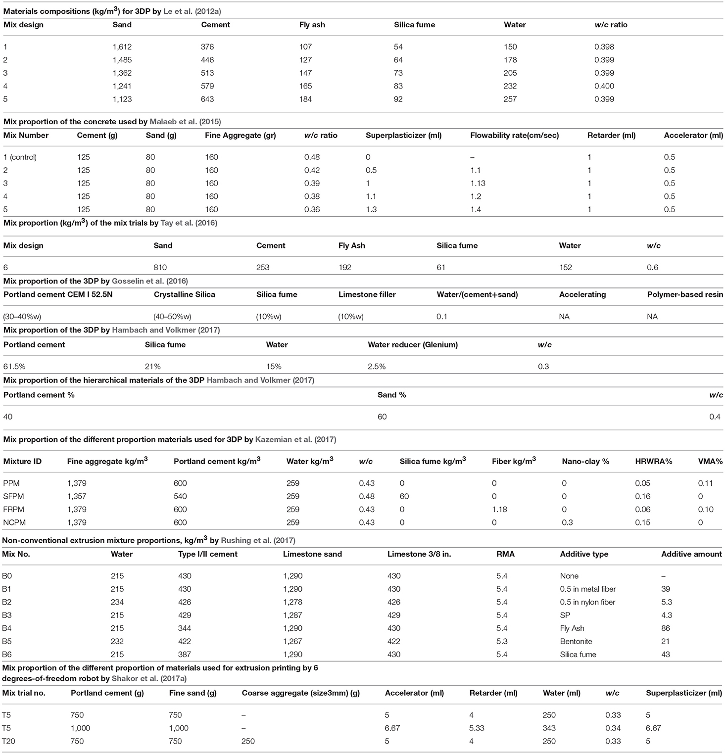
Table 3. Mix design proportions for 3DP concrete and mortar in the literature studies.
Malaeb et al. (2015) have tried different mix proportions of concrete as shown in Table 3 to print straight lines. In their study, they chose mix proportion number 3 in Table 3, which has water to cement (w/c) ratio of ~0.4. The lower w/c ratio which increases the strength of the concrete and suitable water ratio in the concrete assistance to maintain the greatest buildability of the printed concrete. The approximate compressive strength of such mix designs is 42 MPa.
Tay et al. (2016) conducted the 3DP concrete mixture design as described in Table 3. They found that this mixture is an excellent concrete mix design for 3DP. In this study, the low-cost mix design has been produced with 1.05% of water-weight superplasticizer added to the mix. The extrudability and buildability of the printer have been changed according to the mix design variations.
Gosselin et al. (2016) investigated the 3DP mix proportions of concrete (see Table 3). The materials consist of an ultra-high performance mortar paste, with an added polymer resin to improve the quality interfaces between layers and accelerating agents in order to attain adequate rheology. The prisms samples (40 × 40 × 160 mm) has been prepared for 90 days at ambient temperature in order to check the flexural strength test of the specimens. In this work, the 6 degrees-of-freedom robotic arm has been used instead of a moveable crane and also structural printing of the complex geometry has been presented.
Hambach and Volkmer (2017) investigated 3DP mix designs and demonstrated the optimum mix proportion for their study (Table 3). In their paper, they prepared and printed samples using the WASP Clay Extruder Kit machine with a nozzle diameter of 2 mm. The tests investigated the density, porosity and strength of the 3D printed samples with the short fibers (carbon, glass, and basalt fibers). The fibers have been used in different directions and the maximum obtained flexural strength was 30 MPa for the content of 1% volume of carbon fiber for the printed path. The optimum compressive strength for the 1% volume short carbon fibers parallel to the printed part reached 80 MPa.
In the same study, the authors prepared mix proportions for the hierarchical materials. All the different types of fiber reinforcement were used in a dry mix. The water reducer agent was mixed with the water by the particular mixer to make a homogenous mix. Lastly, the fibers continued to be added to the mixture until the fibers dispersed completely. The maximum flexural strength in hierarchical materials for the 3DP is 17.5 ± 0.5 MPa. The optimum three-point bending strength is in the filled mortar diagonal sections of the specimens.
Kazemian et al. (2017) developed the different mix designs for concrete in 3DP. Table 3 shows the different mixtures such as PPM (Portland cement only), SFPM (containing silica fume), FRPM (containing fiber), NCPM (containing nano-clay). Two different methods have been proposed for the shapability “layer settlement” and “cylinder stability.” The experimental results showed that the nano-clay and the silica fume enhanced the shapability of the fresh mixture, whereas little improvement was noticed in the printed part by the addition of polypropylene fiber.
According to the study of Rushing et al. (2017), the mix design for the extrusion printing has been prepared as shown in Table 3. It has been noted that the mixture B3 has the best mix extrusion. An examination of short fiber in the concrete revealed that the short fiber did not decrease the flow and in most cases, the fiber enhanced the shape stability of the fresh concrete.
According to the study performed by Shakor et al. (2017a), the mixture proportion of the concrete could be prepared based on the squeeze flow tests, compressive strength, slump test, and Vicat test. Table 3 shows the pivotal trials for the concrete mixture. In the previous study, it was conducted the various cementitious mixes which are the mortar mixes with various ratio of water and chemical admixture. This could significantly alter the flowability of the concrete. In the study, 22 trials being conducted for the preparation of the concrete printing. Further, three of these trials were chosen for the squeeze flow, mechanical characteristics, and flowability tests. It was determined that the triple layers in trial five, which consisted of a mortar mix, has less displacement than the mix containing a coarse aggregate.
The tables above presented different mix proportions in 3DP printing and used different chemical admixtures to control the rheology of the materials. The different mix ratios resulted in different outcomes and different final shapes of the structural components. Moreover, many of the concrete mixes were cured using a specific procedure. However, each study has a different measurement for the setting time of the concrete slurry based on the w/c and admixture proportions.
In the tables above, the w/c ratio of mortar is between (0.3 and 0.4). In most studies, the w/c ratio used was 0.4. The w/c ratio of the concrete mix in the experimental study has a major effect on the mix flowability and shapability of the printed concrete parts.
The set accelerator ratio has a similar ratio in most of the studies as does the superplasticizer. The concrete mixing time is a vital part of the printing process but was differences in each of the research studies, depending on the mix proportions and water to cement ratio. In the study of Kazemian et al. (2017), mixing process took 8 min, while in Le et al. (2012b) 15 min was used to mix the concrete for the printed specimens. In the previous work which has been performed by Shakor et al. (2017a) the average time of mixing is 5–8 min.
The mix design of concrete has demonstrated the limitations of various mixes. Most of the mixes did not include the coarse aggregate due to the large particle sizes and poor shapability outcomes. Thus, researchers generally choose mortar or fine particles to make it easily pumpable. However, the coarse aggregate could not be applicable to use for all types of pumps. Further, the printed concrete with coarse particles did not look decent feature after printed concrete.
Benchmark Experimental Results
Inkjet Printing
Formulation of the Powder for Inkjet 3DP
In the inkjet 3DP technic, the crucial factor before starting a print is adaptability and compatibility of the powder with the type of the printer. The printing application will be easy whenever the particle size, flowability, and wettability of the powder match with the recommended powder of the printer manufacturer. Accordingly, the particle size analysis of the recommended material is important to find the closest range of the particles that are expected to result a successful print.
In the previous studies by the author Shakor et al. (2017b) and Shakor et al. (2018) distribution size of the powder that has been used in an inkjet 3D printer (Z-printer150, Z-Corporation, USA) has been analyzed and identified. The data has been acquired from particle size laser analyser (Cilas 1190), Figure 5A. Recommended powder (ZP 151) by the manufacturer, contains major materials of plaster, carbohydrate, and vinyl polymer. Descriptive values of the mean particle size for 10, 50, and 90% of the materials are D10, D50, and D90, respectively. The D values that were obtained were equal to 1.48, 23.07, and 70.12 μm, respectively. The specific surface area for the ZP 151 powder was recorded as 0.999 m2/g by (BELSORP-max) machine.
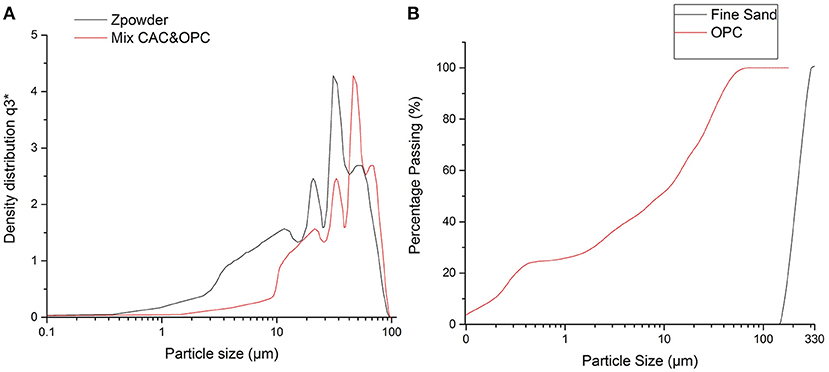
Figure 5. (A) Particle size distribution of cement mortar and Zpowder (ZP 151) for the inkjet printing, (B) Particle size analysis of mortar vs. percentage passing for the extrusion printing.
Figure 5A shows the particle size distribution details of ZP 151 and cement mortar, which has been used in the inkjet printing process. In Figure 5A the particle size of the cement mortar is shown inclined to the right side of the graph, which means the particle size is slightly larger than the recommended powder (ZP 151), which is for D90 values it's about 80 μm for modified powder (cement mortar). From the graph, neither of both powders are perfectly matched, but they are similar enough that helps to ensure the regular flow of the powder through the printer's feeder bin and the ability to print structural specimens smoothly.
Specimen Preparation and Determination of the Water/Cement Ratio
This technique to print construction elements is inkjet printing (binder jetting) similar to the office printer in which, instead of printing on paper, the ink droplet dripping on the powder materials. The D-shape printer also has a similar process. In the binder jetting method, the powder is generally composed of a composite material. The liquid binder is mainly water which is used as an activator to bind the powder. The printing process is conducted using a layer-by-layer application process. Figure 6 shows the cubic specimens under a uniaxial compression load, Figure 6b shows the core and shell of the specimens after the test. The saturation level is defined as the amount of liquid binder on the powder printed bed which is dropped out from the printhead (Miyanaji et al., 2016).
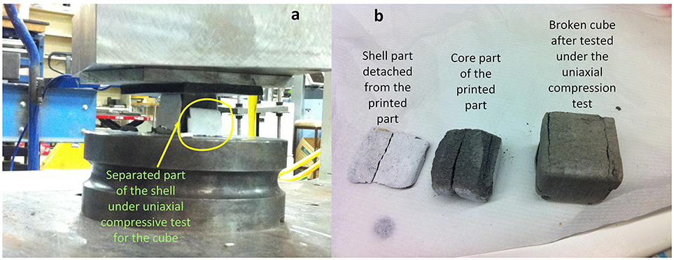
Figure 6. Printed cementitious cube via inkjet 3D printer: (a) Compressed under a uniaxial load, (b) crack and detach of the shell and core parts.
Where Vbinder is the volume of the binder and Venv.powder is the volume of the powder after it has been rolled on the build chamber (bin; enveloped powder).
Since the density and mass are known then equation above can be used to determine the w/c ratio for both materials.
The different saturation levels in the liquid binder mean that the shell and core have a similar w/c ratio and similar saturation levels mean different w/c ratios inside the shell of the cube.
The saturation levels in inkjet printing are based on the interior and exterior of the 3D printed part. The exterior part is called the shell and the interior part is called the core (Withell et al., 2011).
The files for the 3D printing objects are the STL files which can be easily modeled and sent to the printer to print the segments (Cox et al., 2015; Hager et al., 2016).
The printed part under the uniaxial compression load could be broke in various directions according to the direction of printing. Figure 6b, in the same saturation specimens such as (S100 C100), a shell part under a uniaxial compression load detached their parts from the core part of the specimens (Shakor et al., 2017b). Further, investigations are required to determine the reasons behind the observed results, Figure 6.
Resolution and Surface Roughness of the Powder-Bed
After preparing the materials and delivering the powders from the feeder, another variable that should be investigated is the surface roughness of the powder and roughness of the specimens. This variable is mainly related to the bed-powder preparations. One of the methods that can be used to assess the roughness of the powder is a visual inspection of the powder-bed in the build bin of the printer. The visual inspection of different types of gypsum has been performed in the studies by Zhou et al. (2014), which compared coarse and fine powder and also investigated the density of both powders. The distribution of the powder particles, uniformity of powder, hygroscopic properties in the powder has a major contribution to the final printed product. Each of the powder has different properties for electric conductivity and microstructural strength development in the materials.
The modified materials (cement mortar) is more capable of absorbing water and exhibiting hydration reactions. This is due to the main ingredient of powder being calcium aluminate cement, which undergoes an amorphous phase that results in the growth of an interlocked crystal of dense microstructure. Therefore, the high early strength in rapid-setting of the calcium aluminate cement emerged. On the other hand, development of too many crystals causes a porous microstructure and will lead to a reduction in strength and durability (Sugama and Carciello, 1991).
In general, the hygroscopic properties and agglomeration in cement powder cause a poor powder-bed packing in the build chamber of the printer. Thus, the powder needs to be properly mixed and fluidized before printing any objects.
In inkjet printing, there is a clear difference between cement powder and the recommended gypsum powder on the build chamber of the printer. However, Shakor et al. (2018) observed a significant number of porous, voids and roughness on the cement mortar powder. Consequently, this would produce a weak printed sample and lead to a reduction in the mechanical strength of the printed specimens. For that reason, it is highly recommended to mix the materials well before commencing the print process. In addition, use the fresh cementitious powder and control the temperature and humidity in the vitro. Moreover, there are other methods to reduce the moisture contents of the materials and increase the strength, e.g., using glass fiber, which has been used in the other studies to increase the flexibility and strength of the printed structural members (Shakor et al., 2011) and (Shakor and Pimplikar, 2011).
Selective Laser Sintering
The purpose of this study is to explore the capabilities of additive manufacturing and utilize 3D printing to produce scaffolds or structural elements which are currently beneficial to the construction industry.
The SLS test was undertaken for the cementitious paste. This test has been arranged to determine the reaction of materials under the heat of the laser beam and infusion between the particles.
The limited quantities of cement and water were prepared with 630 g of cement and 282 mm of water, respectively, and w/c ratio of 0.45. The thickness of the paste on the tray was 6 mm. In this trial test, the paste has been prepared on the flat tray such that the light of the beam could easily pass over the paste on the tray. The laser was applied to the cementitious paste for the purposes of hardening and drying the slurry of concrete, as shown in Figure 7 and Table 4. It is noticeable that laser sintering did not significantly affect the cement paste and react with the slurry. The laser was also tested at different powers and at various locations on the cement paste, resulting in a slightly dried stain on the surface of the cement paste. These trials were executed using the Voxeljet VX1000 machine. As shown in Figure 7, the first line on the tray is cut by the laser light with a spot size of 1 mm, then the spot size has been increased to 24 mm, which had no noticeable drying effect on the paste, due to the large size of the spot-light. Thus, in the fourth line, the spot-light has been decreased to half (i.e., 12 mm). This dramatically changed the color of the cementitious paste to yellowish, which means burnt. The rest of the lines became dried and dehydrated with the various ratios of spot sizes. For example, line nine became moderately dry compared with the other lines.
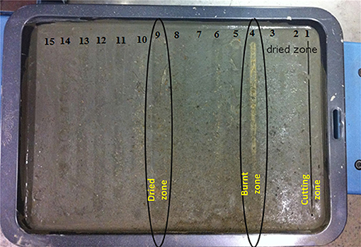
Figure 7. Using laser sintering (SLS) for cement paste using different powers (Watts).
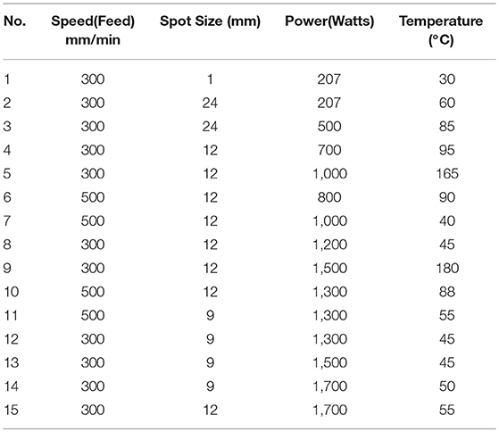
Table 4. Demonstrate the speed, spot size, power, and temperature for each line in Figure 7.
Table 4, it demonstrated the ratio of feed mm/min, the spot size (mm), power (watts), and temperature (°C). It is clear that the speed and temperature are a crucial factor in the SLS process and they both influence the resulting cementitious paste.
Extrusion Printing
Mix Design for Cementitious Materials
As a pilot study, Shakor et al. (2017a) used different concrete mixes and various nozzle sizes with an industrial robot to print cement mortar. The robot was also programmed to print complex components as shown in Figure 8. Currently, extrusion printing is one of the most common methods in construction applications. Extrusion printing [e.g., concrete printing (Le et al., 2012a), contour crafting (Khoshnevis et al., 2001)] have been established in the construction field already.
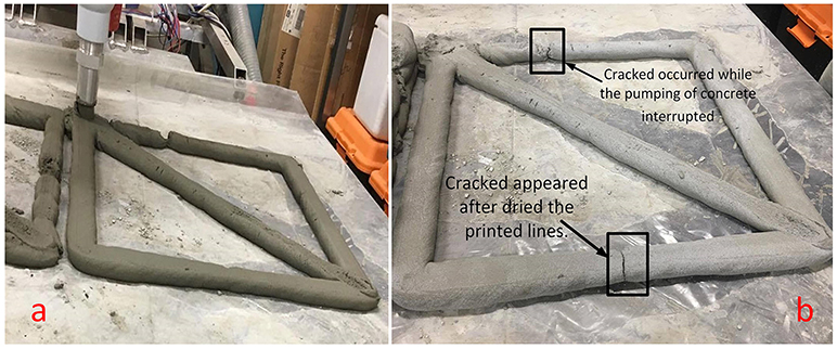
Figure 8. (a) Printed mortar via extrusion printing, (b) Printed mortar by robot extrusion dried in the ambient temperature for 1 day.
The methodology in Gosselin et al. (2016) has been upgraded from a 3DOF design 2.5D printing (Le et al., 2012b) to a 6DOF (3D printing) using an industrial robot. The 2.5D printing is the application process by the 3 axes of the printer, which has limited ability to maneuver the print head. However, the 3D printing is known as a complete process of application by the six degrees of freedom robot which can be smoothly moved with a minimum of boundary limitations.
Figure 8 shows how after the printed lines become dry, shrinkage cracks occurred at the locations where the pump became clogged. This can occur when the delivery pipe does not have enough supply materials coming out of the nozzle. However, the shrinkage cracks can be solved by adding fibers such as glass fiber or polypropylene fibers (Shakor and Pimplikar, 2011) and slightly increasing the w/c ratio (Rashidi et al., 2018) or by adding a wire (308LSo stainless steel) to increase the tensile strength of the printed objects (Laghi et al., 2018). Another limitation that is faced when printing the concrete was the oscillations experienced by joints 4 and 6 of the industrial robot when the robot approaches singular configurations. This problem was initially exacerbated since these joints were experiencing the majority of the motions and changes in velocity. However, this oscillation could be solved by applying the Damped Least Squares (DLS) method for robot singularity avoidance as explained in previous work (Shakor et al., 2017a).
Furthermore, the sieve analysis and particle size distribution of the mortar has a major impact on the flow of the materials and the slump of the mortar. Figure 5B shows the passing percentage of the particles from the sieve for fine sand and ordinary Portland cement vs. the logarithmic particle size for the extrusion printing. It is obvious that the particle size of dry powders is not more than 300 μm. However, the particle size can be increased to larger particles, i.e., 1.0 mm, as coarse sand to improve the strength of the mortar and reduce the shrinkage crack in the printed objects.
Extruder Adaptation and Delivery System
Extruder adaptation and delivery systems have the most significant influence on whether or not extrusion printing will produce a satisfactory printed object. A satisfactory outcome of the printed objects generally means a good mechanical property of the materials and good shapability of the printed parts. Figure 9 shows the developed model for the extruded part that has been designed to mount to the end-effector of the 6-DOF robot in this study.

Figure 9. Concept of extruder assembly in an exploded view that is connected to the progressive cavity pump and is attached to the end of the robot.
The joints of the robots that have been predominantly used during the printing process are joint 4 and 6. These two joints are used frequently to rotate and move the print nozzle through the desired path in order to print the members. For that reason, mostly oscillation appeared in those two joints.
Shape and size of the nozzle are counted as another effective factor to the mechanical strength and shapability of the printed objects. Therefore, these two factors should be taken into account in the design of the nozzle.
Besides, the delivery system is another affecting parameter that needs to be considered. The delivery system has a major impact on the printing outcomes such as shapability and slump of the concrete or mortar. Pumps are the most common delivery system used in the printing applications. Pumps have different types and a different process to delivers the material from the source to the end-effector of the printer. Figure 4 displays the graphical illustration of the printing system via using 6-DOF and a progressive cavity pump in the current study (Shakor et al., 2017a). In 3DP by concrete, various pumps have been used such as a progressive cavity pump (Shakor et al., 2017a), peristaltic pump (Gosselin et al., 2016), pneumatic pump (Bos et al., 2018), and piston pump (Malaeb et al., 2015). Each of the pumps had limitations such as pressure, flow rate and heat transmission to the slurry. Thus, none of the pumps is perfect with 100% efficiency. Losing energy and transforming heat into the slurry makes the pump warmer and concrete warm as well. However, some of the pumps have less cavity and air voids than the others such as pneumatic, or centrifugal, and peristaltic pumps. The aforementioned types of pumps cause less air entertaining due to the working principle of the turbine and easy-place dampeners in such pumps. The design of progressive cavity pumps makes cavities and voids which would lead to air being discharged at the end of the rotor with materials. Moreover, when the operating time increases in the pump the flow rate of the pumps decreases dramatically in contrast to the flow rate in the rotary lobe which stays steady and constant (Boring, 2016).
Discussion
Inkjet printing is the second best-known printing process in the construction field and consists of a powder and a binder. The powders could be any usable materials, which can easily react with the binder.
Chua and Leong (2014) and Low et al. (2017) referred to large printers such as Voxeljet and ExOne, which can print large parts up to (4 2 1 m). Voxeljet is a German company which specializes in 3D printing system services. Additionally, ExOne is an American company that has similar services to Voxeljet, the only differences being some technical specifications. For instance, the ExOne has two build chambers and can print at the same time but Voxeljet has only one chamber. The build chamber sizes of Voxeljet are larger than ExOne and reaches (4 2 1 m), but the maximum dimensions of ExOne reach (2.2 1.2 0.6) 2 m.
Nowadays, the main competition between these printers relates to resolution and speed, which have a significant role in the appearance and the mechanical behavior of the manufactured parts. Chuang (2017) claimed that when the cartridge mounting angle changed from 1.1 to 90°, the resolution of inkjet printing changed from 5080 to 100 dpi. The outcome increases in drop spacing from 5 to 254 μm. The printed dots have an undesirably large overlap when the drop spacing is too close (short), causing a large spread of the ink because of an efflux of the ink. On the other hand, a non-uniform width line or a separated dot occurs when the drop spacing is too great to overlap each dot.
One of the limitations of the inkjet printing is the high porosity which makes the sample more fragile and permeable (i.e., will easily pass water through it). Therefore, extra post-processing is required, such as curing in heat or with pressurized water steam (Dikshit et al., 2018).
On the other hand, the high porosity makes the 3D printed part very light and easy to handle which could be very beneficial for print the structural components. It reduces the weight in the building and could be very effective for the seismic zone region.
In Zhou et al. (2014) the study proposed the density of the powder over the build chamber, which is called the in-process bed density. This density is usually lower than the true density and higher than the bulk density in magnitude. However, the enhancement could be implied by the type of packing the bed powder on the chamber by changing the mechanical force applied on the powder bed. This can increase the required force of the roller on the bed layers which helps to reduce the voids within the powder particles. The outcome will be a higher density and less porosity, which will, in turn, eliminate or reduce extra post-processing.
Table 5 explains the printer settings of an inkjet printer, extrusion printer, and Selective Laser Sintering.
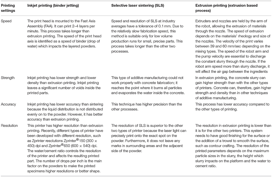
Table 5. Explanation of settings of printing and printing methods.
SLS has broad applications in other fields, but in the construction field, it has limited use. The main materials used in this process are powders. Most powders consumed in this application are a polymer (nylon). In the SLS process, the powders are fused or reacted together using a laser. If the powders do not react using a laser, it is not an effective method.
In some studies, the SLS technique has been proceeding for the dental work, the SLS and conventional process have been conducted. In the process, noticed that the casting the gap in the SLS production is greater than the conventional casting in all measured field (Kim et al., 2013). Thus, the methodology of the SLS is similar to the inkjet printing processing, which produces similar voids among particles.
Another limitation in the SLS is the low resolution due to the restrictions of the powder-base materials, which is face to agglomerate fine particle sizes (Cao et al., 2015).
Extrusion printing has the greatest potential for use in the construction field compared with other techniques of additive manufacturing. There are particular limitations in extrusion printing that can be addressed based on the scale of the project and the printing materials (Wu et al., 2016).
Berman (2012) demonstrated that rapid prototyping is the most successful process for manufacturing small parts of the scaffold.
A question that has been frequently asked is whether 3DP could print at a larger scale for components in construction with durable mechanical properties. However, this question has been answered in recent decades with the development of additive manufacturing. For instance, the WinSun company in China has built precast components with dimensions of 150 10 6.6 m (Feng, 2014). However, it has not been proven to what degree these 3D printed elements can withstand severe environments and weather conditions.
Furthermore, the pumping speed and the velocity of the moving arm or nozzle (delivery mechanism) were found to have a crucial impact on the printed objects and resolution of the samples. Shakor et al. (2017a) conducted a comprehensive experimental study with various concrete mixes in regard to the speed of the robot, as shown in Table 6. The optimum velocity of the robot printhead is 39.36 mm/s, for the total length of the printed line (1,580) mm, however when using the auger motor speed in the adapted extruder is 15–19 volts.
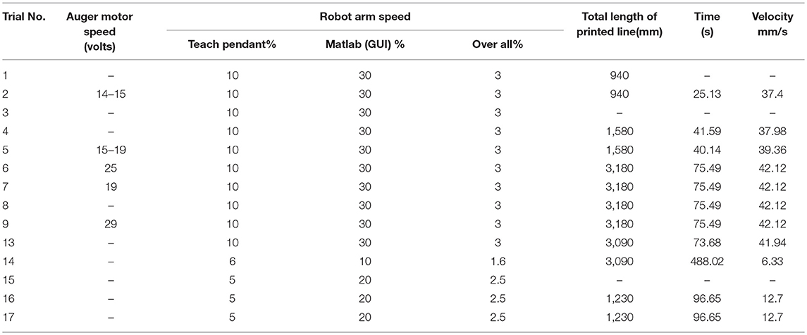
Table 6. Explains the time and velocity of the printed concrete outcomes.
The study by El Cheikh et al. (2017) explored the speed of the horizontal plane shifting with a constant speed (Vp) equal to 50 d/s, where d/s is the diameter of the tube per second. The study by Hambach and Volkmer (2017) obtained a print speed of 30 mm/s by adjusting the layer height to 1.5 mm. Kazemian et al. (2017) used a linear printing speed of 60 mm/s. However, Shakor et al. (2017a) proved in their study that the most appropriate robot arm speed is suitable for printing concrete was 39.36 mm/s for their mix design.
The printing speed to extrude materials depends on several factors: rheology of the materials, the size of the nozzle, the shape of the nozzle, the distance between the nozzle, and printed platform and the distance between the delivery method and the extruder.
Modeling in 3D Printing
The studies that have been analyzed show that different mixes should be designed based on the printing technique employed. The concrete could be printed by different AM processes such as 2.5DP or 3DP. For instance, the 2.5DP process has been implemented by Lim et al. (2012), by installing a moveable frame in three directions and the 3DP has been performed by Gosselin et al. (2016) which is prepared short column mortar via robot to fabricate the complex printed geometry.
Another important issue in 3D printing is the mechanical properties (stiffness and strength) of the printed material in relation to its microstructure. The presence of aggregates in the concrete could enhance its mechanical properties (Wu et al., 2001). Instead of large aggregates commonly used in concrete, smaller ones (2~4 mm) could be accommodated in the mix to enhance the mechanical properties of the cement (Lee et al., 2007). Additionally, short fibers (steel, carbon, or wood), and some waste materials such as fly ash and slag could be introduced into the mix design (Hambach and Volkmer, 2017) to improve the mechanical properties of the printed material. Although new extrusion printers (like the one designed by the authors) offers flexibility in the 3D printing of complex structures with various concrete mixes, optimal mix designs for a specific application (or load condition) require developing versatile multi-scale models and different geometries. Recently, a computational multi-scale model has been developed at MIT for 3D printing of short fiber composites (Malek et al., 2017) so as to better understand the effect of various design parameters on the effective properties of the printed material. The authors are currently developing a similar multi-scale model for 3D printing of reinforced concrete with short fibers.
In addition to mechanical behavior, the printability, and flow behavior of the material would be affected by changing the mix design (Lim et al., 2012). Therefore, predicting the rheological properties of the cement paste with fillers needs to be integrated with the above multi-scale model. It is envisioned that the development of an integrated modeling framework for concrete, similar to those developed for advanced fiber reinforced composites (Johnston et al., 2001; Haghshenas et al., 2018), would offer the smart design and printing of various concrete mixes in the next decades.
Conclusion
Various additive manufacturing techniques that could be employed for plotting/printing in the construction industry have been reviewed in this paper. The choice of the printer, mix design, and the method of printing was discussed. Three benchmark examples were selected to compare the features and limitations of various techniques for 3D printing of concrete. Results showed that extrusion printing with industrial robotic arms is a versatile technique that could be adapted for rapid and bespoke construction projects. Several parameters and printer features including the speed, strength, accuracy, and resolution of printing along with concrete mix were studied. It was found that by controlling various features of the extrusion printer such as speed, nozzle diameter, and the distance from the substrate, different concrete mixes could be printed; therefore, constructing a wide range of complex structures with different sizes is achievable in the future. However, further research is still required to improve (and predict) the mechanical properties and printability of the 3D printed structural elements. Notably, the rheology of the mix and the relations with the orthotropic properties of the concrete need further investigation. Future work will focus on the development of physically-based models at various scales (i.e., neat cement, filled cement, and finished concrete), which in turn would enable the printing parameters involved in the extrusion technique to be optimized.
Author Contributions
PS and SN contributed conception and idea of the review paper. PS organized all the database and interpreting the mix design of review papers. SM performed to interpret the modeling section. GP reviews the first draft of the manuscript and check all the mechatronic subjects related to his field. PS, SN, GP, and SM reviewed all the sections in the manuscript. All authors contributed to organizing the manuscript, read, revision, and approved the submitted version.
Conflict of Interest Statement
The authors declare that the research was conducted in the absence of any commercial or financial relationships that could be construed as a potential conflict of interest.
Acknowledgments
The authors would like to show their gratitude to the Swinburne University of Technology (Center for Sustainable Infrastructure) for SLS machine. The authors would also like to express their sincere gratitude to the Sika Australia for their chemical material supply and Elasto Plastic Concrete for providing materials.
References
Ambrosi, A., and Pumera, M. (2016). 3D-printing technologies for electrochemical applications. Chem. Soc. Rev, 45, 2740–2755. doi: 10.1039/C5CS00714C
Ashraf, M., Gibson, I., and Rashed, M. G. (2018). “Challenges and prospects of 3d printing in structural engineering,” in 13th International Conference on Steel, Space and Composite Structures (Perth, WA).
Barnett, E., and Gosselin, C. (2015). Large-scale 3D printing with a cable-suspended robot. Additive Manufactur. 7, 27–44. doi: 10.1016/j.addma.2015.05.001
Berman, B. (2012). 3-D printing: the new industrial revolution. Business Horizons 55, 155–162. doi: 10.1016/j.bushor.2011.11.003
Boring, R. J. (2016). Rotary Lobe Pumps Versus Progressive Cavity Pumps. Available online at: https://www.flowcontrolnetwork.com/rotary-lobe-pumps-versus-progressive-cavity-pumps/.
Bos, F., Wolfs, R., Ahmed, Z., and Salet, T. (2016). Additive manufacturing of concrete in construction: potentials and challenges of 3D concrete printing. Virtu. Phys. Prototyp. 11, 209–225. doi: 10.1080/17452759.2016.1209867
Bos, F. P., Ahmed, Z. Y., Wolfs, R. J. M., and Salet, T. A. M. (2018). 3D Printing Concrete with Reinforcement. High Tech Concrete: Where Technology and Engineering Meet. Cham: Springer International Publishing. 2484–2493. doi: 10.1007/978-3-319-59471-2_283
Brown, A. (2015). 3D printing in instructional settings: identifying a curricular hierarchy of activities. TechTrends 59, 16–24. doi: 10.1007/s11528-015-0887-1
Buswell, R. A., Soar, R., Gibb, A. G., and Thorpe, A. (2007). Freeform construction: mega-scale rapid manufacturing for construction. Automat. Construct. 16, 224–231. doi: 10.1016/j.autcon.2006.05.002
Cao, S., Qiu, Y., Wei, X.-F., and Zhang, H.-H. (2015). Experimental and theoretical investigation on ultra-thin powder layering in three dimensional printing (3DP) by a novel double-smoothing mechanism. J. Mater. Process. Technol. 220, 231–242. doi: 10.1016/j.jmatprotec.2015.01.016
Castilho, M., Dias, M., Gbureck, U., Groll, J., Fernandes, P., Pires, I., et al. (2013). Fabrication of computationally designed scaffolds by low temperature 3D printing. Biofabrication 5:035012. doi: 10.1088/1758-5082/5/3/035012
Castilho, M., Gouveia, B., Pires, I., Rodrigues, J., and Pereira, M. (2015). The role of shell/core saturation level on the accuracy and mechanical characteristics of porous calcium phosphate models produced by 3Dprinting. Rapid Prototyp. J. 21, 43–55. doi: 10.1108/RPJ-02-2013-0015
Castilho, M., Pires, I., Gouveia, B., and Rodrigues, J. (2011). Structural evaluation of scaffolds prototypes produced by three-dimensional printing. Int. J. Adv. Manufact. Technol. 56, 561–569. doi: 10.1007/s00170-011-3219-4
Christ, S., Schnabel, M., Vorndran, E., Groll, J., and Gbureck, U. (2015). Fiber reinforcement during 3D printing. Mater. Lett. 139, 165–168. doi: 10.1016/j.matlet.2014.10.065
Chua, C. K., and Leong, K. F. (2014). 3D printing And Additive Manufacturing: Principles and Applications (With Companion Media Pack) of Rapid Prototyping. Singapore: Singapore World Scientific Publishing Co Inc.
Cole, R. J. (1998). Energy and greenhouse gas emissions associated with the construction of alternative structural systems. Build. Environ. 34, 335–348. doi: 10.1016/S0360-1323(98)00020-1
Cox, S. C., Thornby, J. A., Gibbons, G. J., Williams, M. A., and Mallick, K. K. (2015). 3D printing of porous hydroxyapatite scaffolds intended for use in bone tissue engineering applications. Mater. Sci. Eng. C, 47(Suppl. C), 237–247. doi: 10.1016/j.msec.2014.11.024
Dalgarno, K., and Stewart, T. (2001). Manufacture of production injection mould tooling incorporating conformal cooling channels via indirect selective laser sintering. Proc. Institut. Mech. Eng. B 215, 1323–1332. doi: 10.1243/0954405011519042
Delgado Camacho, D., Clayton, P., O'Brien, W. J., Seepersad, C., Juenger, M., Ferron, R., et al. (2018). Applications of additive manufacturing in the construction industry – a forward-looking review. Automat. Construct. 89, 110–119. doi: 10.1016/j.autcon.2017.12.031
Dikshit, V., Nagalingam, A. P., Yap, Y. L., Sing, S. L., Yeong, W. Y., and Wei, J. (2018). Crack monitoring and failure investigation on inkjet printed sandwich structures under quasi-static indentation test. Mater. Design 137, 140–151. doi: 10.1016/j.matdes.2017.10.014
Edwards, L., Holt, C., Keyte, L., and Lloyd, R. (2013). “Construction 3D Printing”, in Concrete (Gold Coast, QLD).
El Cheikh, K., Rémond, S., Khalil, N., and Aouad, G. (2017). Numerical and experimental studies of aggregate blocking in mortar extrusion. Construct. Build. Mater. 145, 452–463. doi: 10.1016/j.conbuildmat.2017.04.032
Elhag, H., Glass, J., Gibb, A. G., Clarke, M., Budge, C., and Bailey, G. (2008). Implementing environmental improvements in a manufacturing context: a structured approach for the precast concrete industry. Int. J. Environ. Technol. Manag. 8, 369–384. doi: 10.1504/IJETM.2008.017508
Farzadi, A., Waran, V., Solati-Hashjin, M., Asadi-Eydivand, M., and Abu Osman, N. A. (2014). Effect of layer thickness and printing orientation on mechanical properties and dimensional accuracy of 3D printed porous samples for bone tissue engineering. PLoS ONE 9:e108252. doi: 10.1371/journal.pone.0108252
Farzadi, A., Waran, V., Solati-Hashjin, M., Rahman, Z. A. A., Asadi, M., and Osman, N. A. A. (2015). Effect of layer printing delay on mechanical properties and dimensional accuracy of 3D printed porous prototypes in bone tissue engineering. Ceramics Int. 41, 8320–8330. doi: 10.1016/j.ceramint.2015.03.004
Feng, L. Y. (2014). Study on the status quo and problems of 3D printed buildings in China. Global J. Hum. Soc. Sci. Res. 14:5.
Feng, P., Meng, X., Chen, J.-F., and Ye, L. (2015a). Mechanical properties of structures 3D printed with cementitious powders. Construct. Build. Mater. 93, 486–497. doi: 10.1016/j.conbuildmat.2015.05.132
Feng, P., Meng, X., and Zhang, H. (2015b). Mechanical behavior of FRP sheets reinforced 3D elements printed with cementitious materials. Composite Struct. 134, 331–342. doi: 10.1016/j.compstruct.2015.08.079
Gharaie, S. H., Morsi, Y., and Masood, S. H. (2013). Tensile properties of processed 3D printer ZP150 powder material. Adv. Mater. Res. 699, 813–816. doi: 10.4028/www.scientific.net/AMR.699.813
Gibbons, G. J., Williams, R., Purnell, P., and Farahi, E. (2010). 3D printing of cement composites. Adv. Appl. Ceramics 109, 287–290. doi: 10.1179/174367509X12472364600878
Gosselin, C., Duballet, R., Roux, P., Gaudillière, N., Dirrenberger, J., and Morel, P. (2016). Large-scale 3D printing of ultra-high performance concrete – a new processing route for architects and builders. Mater. Design 100, 102–109. doi: 10.1016/j.matdes.2016.03.097
Hager, I., Golonka, A., and Putanowicz, R. (2016). 3D printing of buildings and building components as the future of sustainable construction? Proc. Eng. 151, 292–299. doi: 10.1016/j.proeng.2016.07.357
Haghshenas, S. M., Vaziri, R., and Poursartip, A. (2018). Integration of resin flow and stress development in process modelling of composites: part II - transversely isotropic formulation. J. Comp. Mater. 52, 3157–3171. doi: 10.1177/0021998318762296
Hambach, M., and Volkmer, D. (2017). Properties of 3D-printed fiber-reinforced Portland cement paste. Cement Concrete Composites 79, 62–70. doi: 10.1016/j.cemconcomp.2017.02.001
Henke, K., and Treml, S. (2012). Wood based bulk material in 3D printing processes for applications in construction. Eur. J. Wood Wood Products 71, 139–141. doi: 10.1007/s00107-012-0658-z
Hwang, D., and Khoshnevis, B. (2004). “Concrete wall fabrication by contour crafting,” in 21st International Symposium on Automation and Robotics in Construction (ISARC 2004), Jeju. doi: 10.22260/ISARC2004/0057
Ian, G., and Dongping, S. (1997). Material properties and fabrication parameters in selective laser sintering process. Rapid Prototyp. J. 3, 129–136. doi: 10.1108/13552549710191836
Jeng, J.-Y., Peng, S.-C., and Chou, C.-J. (2000). Metal rapid prototype fabrication using selective laser cladding technology. Int. J. Adv. Manufact. Technol. 16, 681–687. doi: 10.1007/s001700070039
Jeon, K.-H., Park, M.-B., Kang, M.-K., and Kim, J.-H. (2013). “Development of an automated freeform construction system and its construction materials,” in Proceedings of the 30th International Symposium on Automation and Robotics in Construction and Mining. Citeseer. 1359–1365. doi: 10.22260/ISARC2013/0153
Jianchao, Z., Zhang, T., Faried, M., and Wengang, C. (2017). “3D printing cement based ink, and it's application within the construction industry,” in MATEC Web of Conferences (Malacca: EDP Sciences).
Johnston, A., Vaziri, R., and Poursartip, A. (2001). A plane strain model for process-induced deformation of laminated composite structures. J. Composite Mater. 35, 1435–1469. doi: 10.1106/YXEA-5MH9-76J5-BACK
Kazemian, A., Yuan, X., Cochran, E., and Khoshnevis, B. (2017). Cementitious materials for construction-scale 3D printing: laboratory testing of fresh printing mixture. Construct. Build. Mater. 145, 639–647. doi: 10.1016/j.conbuildmat.2017.04.015
Khoshnevis, B., Bukkapatnam, S., Kwon, H., and Saito, J. (2001). Experimental investigation of contour crafting using ceramics materials. Rapid Prototyp. J. 7, 32–42. doi: 10.1108/13552540110365144
Khoshnevis, B., and Dutton, R. (1998). Innovative rapid prototyping process makes large sized, smooth surfaced complex shapes in a wide variety of materials. Mater. Technol. 13, 53–56. doi: 10.1080/10667857.1998.11752766
Kim, K.-B., Kim, J.-H., Kim, W.-C., Kim, H.-Y., and Kim, J.-H. (2013). Evaluation of the marginal and internal gap of metal-ceramic crown fabricated with a selective laser sintering technology: two-and three-dimensional replica techniques. J. Adv. Prosthodontics, 5, 179–186. doi: 10.4047/jap.2013.5.2.179
Kolossov, S., Boillat, E., Glardon, R., Fischer, P., and Locher, M. (2004). 3D FE simulation for temperature evolution in the selective laser sintering process. Int. J. Machine Tools Manufact. 44, 117–123. doi: 10.1016/j.ijmachtools.2003.10.019
Kruth, J. P., Mercelis, P., Van Vaerenbergh, J., Froyen, L., and Rombouts, M. (2005). Binding mechanisms in selective laser sintering and selective laser melting. Rapid Prototyp. J. 11, 26–36. doi: 10.1108/13552540510573365
Kumar, S. (2003). Selective laser sintering: a qualitative and objective approach. JOM 55, 43–47. doi: 10.1007/s11837-003-0175-y
Laghi, V., Palermo, M., Pragliola, M., Girelli, V. A., Velden, G. V. D., and Trombetti, T. (2018). “Towards 3D-printed steel grid-shells: the main idea and first studies,” in Proceedings of the IASS Symposium 2018 Creativity in Structural Design. Boston: IASS2018.
Le, H. P. (1998). Progress and trends in ink-jet printing technology. J. Imaging Sci. Technol. 42, 49–62.
Le, T. T., Austin, S. A., Lim, S., Buswell, R. A., Gibb, A. G. F., and Thorpe, T. (2012a). Mix design and fresh properties for high-performance printing concrete. Mater. Struct. 45, 1221–1232. doi: 10.1617/s11527-012-9828-z
Le, T. T., Austin, S. A., Lim, S., Buswell, R. A., Law, R., Gibb, A. G. F., et al. (2012b). Hardened properties of high-performance printing concrete. Cement Concrete Res. 42, 558–566. doi: 10.1016/j.cemconres.2011.12.003
Lee, C. S., Kim, S. G., Kim, H. J., and Ahn, S. H. (2007). Measurement of anisotropic compressive strength of rapid prototyping parts. J. Mater. Process. Technol. 187–188, 627–630. doi: 10.1016/j.jmatprotec.2006.11.095
Lewis, J. A., Smay, J. E., Stuecker, J., and Cesarano, J. (2006). Direct ink writing of three-dimensional ceramic structures. J. Am. Ceramic Soc. 89, 3599–3609. doi: 10.1111/j.1551-2916.2006.01382.x
Li, T., Aspler, J., Kingsland, A., Cormier, L. M., and Zou, X. (2016). 3d printing–a review of technologies, markets, and opportunities for the forest industry. J. Sci. Technol. For. Prod. Process, 5:30.
Lim, S., Buswell, R. A., Le, T. T., Austin, S. A., Gibb, A. G. F., and Thorpe, T. (2012). Developments in construction-scale additive manufacturing processes. Automat. Construct. 21, 262–268. doi: 10.1016/j.autcon.2011.06.010
Lim, S., Buswell, R. A., Valentine, P. J., Piker, D., Austin, S. A., and De Kestelier, X. (2016). Modelling curved-layered printing paths for fabricating large-scale construction components. Additive Manufactur. 12(Part B), 216–230. doi: 10.1016/j.addma.2016.06.004
Lipson, H., and Kurman, M. (2013). Fabricated: The New World of 3D Printing. New York, NY: John Wiley and Sons.
Lloret, E., Shahab, A. R., Linus, M., Flatt, R. J., Gramazio, F., Kohler, M., et al. (2015). Complex concrete structures: merging existing casting techniques with digital fabrication. Comput. Aided Design 60, 40–49. doi: 10.1016/j.cad.2014.02.011
Low, Z.-X., Chua, Y. T., Ray, B. M., Mattia, D., Metcalfe, I. S., and Patterson, D. A. (2017). Perspective on 3D printing of separation membranes and comparison to related unconventional fabrication techniques. J. Membrane Sci. 523, 596–613. doi: 10.1016/j.memsci.2016.10.006
Lu, K., Hiser, M., and Wu, W. (2009). Effect of particle size on three dimensional printed mesh structures. Powder Technol. 192, 178–183. doi: 10.1016/j.powtec.2008.12.011
Lu, K., and Reynolds, W. T. (2008). 3DP process for fine mesh structure printing. Powder Technol. 187, 11–18. doi: 10.1016/j.powtec.2007.12.017
Ma, G., Wang, L., and Ju, Y. (2017). State-of-the-Art of 3D Printing Technology of Cementitious Material—An Emerging Technique for Construction. Sci. China Technol. Sci. 61, 475–495. doi: 10.1007/s11431-016-9077-7
Malaeb, Z., Hachem, H., Tourbah, A., Maalouf, T., El Zarwi, N., and Hamzeh, N. (2015). 3d concrete printing: machine and mix design. Int. J. Civil Eng. 6, 14–22.
Malek, S., Raney, J. R., Lewis, J. A., and Gibson, L. J. (2017). Lightweight 3D cellular composites inspired by balsa. Bioinspir. Biomim. 12, 026014. doi: 10.1088/1748-3190/aa6028
Marchelli, G., Prabhakar, R., Storti, D., and Ganter, M. (2011). The guide to glass 3D printing: developments, methods, diagnostics and results. Rapid Prototyp. J. 17, 187–194. doi: 10.1108/13552541111124761
Miyanaji, H., Zhang, S., Lassell, A., Zandinejad, A. A., and Yang, L. (2016). Optimal process parameters for 3D printing of porcelain structures. Proc. Manufactur. 5, 870–887. doi: 10.1016/j.promfg.2016.08.074
Mueller, S., Im, S., Gurevich, S., Teibrich, A., Pfisterer, L., Guimbretiere, F., et al. (2014). “WirePrint: 3D printed previews for fast prototyping,” in Proceedings of the 27th Annual ACM Symposium on User Interface Software and Technology. Honolulu, HI: ACM, 273–280. doi: 10.1145/2642918.2647359
Mukesh, A., David, B., Joseph, B., Harris, M., and Joel, B. (1995). Direct selective laser sintering of metals. Rapid Prototyp. J. 1, 26–36. doi: 10.1108/13552549510078113
Nerella, V. N., Schroefl, C., Yazdi, M. A., Alghazali, A., Secrieru, E., Shyshko, S., et al. (2017). “Micro-and macroscopic investigations on the interface between layers of 3d-printed cementitious elements,” in ICACMS 2017 International Conference on Advances in Construction Materials and Systems, Chennai.
Ngo, T. D., Kashani, A., Imbalzano, G., Nguyen, K. T. Q., and Hui, D. (2018). Additive manufacturing (3D printing): a review of materials, methods, applications and challenges. Composites B Eng. 143, 172–196. doi: 10.1016/j.compositesb.2018.02.012
Pegna, J. (1997). Exploratory investigation of solid freeform construction. Automat. Construct., 5, 427–437. doi: 10.1016/S0926-5805(96)00166-5
Perrot, A., Rangeard, D., and Pierre, A. (2015). Structural built-up of cement-based materials used for 3D-printing extrusion techniques. Mater. Struct. 49, 1–8. doi: 10.1617/s11527-015-0571-0
Peter, M., and Jean-Pierre, K. (2006). Residual stresses in selective laser sintering and selective laser melting. Rapid Prototyp. J. 12, 254–265. doi: 10.1108/13552540610707013
Rael, R., and San Fratello, V. (2011). Material Design and Analysis for 3D-Printed Fiber-Reinforced Cement Polymer Building Components. California, CA: RAEL SAN FRATELLO STUDIO.
Rashidi, M., Ashtiani, R. S., Si, J., Izzo, R. P., and McDaniel, M. (2018). A practical approach for the estimation of strength and resilient properties of cementitious materials. Transport. Res. Rec. 2018:0361198118769900. doi: 10.1177/0361198118769900
Rushing, T. S., Al-Chaar, G., Eick, B. A., Burroughs, J., Shannon, J., Barna, L., et al. (2017). Investigation of concrete mixtures for additive construction. Rapid Prototyp. J. 23, 74–80. doi: 10.1108/RPJ-09-2015-0124
Shakor, P., Nejadi, S., Paul, G., and Sanjayan, J. (2018). “A novel methodology of powder-based cementitious materials in 3D inkjet printing for construction applications,” in Sixth International Conference on Durability of Concrete Structures. (Leeds, UK: Whittles Publishing).
Shakor, P., Pimplikar, S., and Ghare, U. (2011). Techno-Commercial aspects of use of glass fibre in construction industry, Advances and Trends in Engineering Materials and their Applications, Montreal; Ottawa, ON: Advanced Engineering Solutions.
Shakor, P., Renneberg, J., Nejadi, S., and Paul, G. (2017a). “Optimisation of different concrete mix designs for 3D printing by utilising 6DOF industrial robot, ISARC,” in Proceedings of the International Symposium on Automation and Robotics in Construction. Taipei: Vilnius Gediminas Technical University, Department of Construction Economics and Property.
Shakor, P., Sanjayan, J., Nazari, A., and Nejadi, S. (2017b). Modified 3D printed powder to cement-based material and mechanical properties of cement scaffold used in 3D printing. Construct. Building Mater. 138, 398–409. doi: 10.1016/j.conbuildmat.2017.02.037
Shakor, P. N., and Pimplikar, S. (2011). Glass fibre reinforced concrete use in construction. Int. J. Technol. Eng. Syst. 2:2.
Shofner, M., Lozano, K., Rodríguez-Macías, F., and Barrera, E. (2003). Nanofiber-reinforced polymers prepared by fused deposition modeling. J. Appl. Polymer Sci. 89, 3081–3090. doi: 10.1002/app.12496
Spath, S., and Seitz, H. (2013). Influence of grain size and grain-size distribution on workability of granules with 3D printing. Int. J. Adv. Manufactur. Technol. 70, 135–144. doi: 10.1007/s00170-013-5210-8
Sugama, T., and Carciello, N. R. (1991). Strength development in phosphate-bonded calcium aluminate cements. J. Am. Ceramic Soc. 74, 1023–1030. doi: 10.1111/j.1151-2916.1991.tb04338.x
Tam, V. W., Tam, C., Chan, J. K., and Ng, W. C. (2006). Cutting construction wastes by prefabrication. Int. J. Construct. Manag. 6, 15–25. doi: 10.1080/15623599.2006.10773079
Tay, Y. W., Panda, B., Paul, S. C., Mohamed, N. A. N., Tan, M. J., Leong, K. F., et al. (2016). Processing and Properties of Construction Materials for 3D Printing. Materials Science Forum.
Tay, Y. W. D., Panda, B., Paul, S. C., Mohamed, N. A. N., Tan, M. J., and Leong, K. F. (2017). 3D printing trends in building and construction industry: a review. Virtu. Phys. Prototyp. 12, 261–276. doi: 10.1080/17452759.2017.1326724
Utela, B., Storti, D., Anderson, R., and Ganter, M. (2008). A review of process development steps for new material systems in three dimensional printing (3DP). J. Manufactur. Process. 10, 96–104. doi: 10.1016/j.jmapro.2009.03.002
Vaezi, M., and Chua, C. (2011). Effects of layer thickness and binder saturation level parameters on 3D printing process. Int. J. Adv. Manufactur. Technol. 53, 275–284. doi: 10.1007/s00170-010-2821-1
Vlasea, M., Pilliar, R., and Toyserkani, E. (2015a). Control of structural and mechanical properties in bioceramic bone substitutes via additive manufacturing layer stacking orientation. Additive Manufactur. 6, 30–38. doi: 10.1016/j.addma.2015.03.001
Vlasea, M., Toyserkani, E., and Pilliar, R. (2015b). Effect of gray scale binder levels on additive manufacturing of porous scaffolds with heterogeneous properties. Int. J. Appl. Ceramic Technol. 12, 62–70. doi: 10.1111/ijac.12316
Weger, D., Lowke, D., and Gehlen, C. (2016). “3D printing of concrete structures with calcium silicate based cements using the selective cinding method–effects of concrete technology on penetration depth of cement paste,” in Ultra-High Performance Concrete and High Performance Construction Materials, HiPerMat 2016, 193.
Withell, A., Diegel, O., Grupp, I., Reay, S., de Beer, D., and Potgieter, J. (2011). “Porous ceramic filters through 3D printing, innovative developments in virtual and physical prototyping,” in Proceedings of the 5th International Conference on Advanced Research in Virtual and Rapid Prototyping (Leiria: CRC Press), 313.
Wu, K.-R., Chen, B., Yao, W., and Zhang, D. (2001). Effect of coarse aggregate type on mechanical properties of high-performance concrete. Cement Concrete Res. 31, 1421–1425. doi: 10.1016/S0008-8846(01)00588-9
Wu, P., Wang, J., and Wang, X. (2016). A critical review of the use of 3-D printing in the construction industry. Automat. Construct. 68, 21–31. doi: 10.1016/j.autcon.2016.04.005
Zein, I., Hutmacher, D. W., Tan, K. C., and Teoh, S. H. (2002). Fused deposition modeling of novel scaffold architectures for tissue engineering applications. Biomaterials 23, 1169–1185. doi: 10.1016/S0142-9612(01)00232-0
Zhou, Z., Buchanan, F., Mitchell, C., and Dunne, N. (2014). Printability of calcium phosphate: calcium sulfate powders for the application of tissue engineered bone scaffolds using the 3D printing technique. Mater. Sci. Eng. C Mater. Biol. Appl. 38, 1–10. doi: 10.1016/j.msec.2014.01.027
Zhou, Z., Mitchell, C. A., Buchanan, F. J., and Dunne, N. J. (2013). Effects of heat treatment on the mechanical and degradation properties of 3D-printed calcium-sulphate-based scaffolds. ISRN Biomaterials 2013, 1–10. doi: 10.5402/2013/750720
Keywords: extrusion printing, inkjet 3D printing, construction, cement mortar, cementitious mix design
Citation: Shakor P, Nejadi S, Paul G and Malek S (2019) Review of Emerging Additive Manufacturing Technologies in 3D Printing of Cementitious Materials in the Construction Industry. Front. Built Environ. 4:85. doi: 10.3389/fbuil.2018.00085
Received: 29 September 2018; Accepted: 19 December 2018;
Published: 23 January 2019.
Edited by:
Michele Palermo, University of Bologna, ItalyReviewed by:
Henrique de Amorim Almeida, Polytechnic Institute of Leiria, PortugalPhilippe Morel, Ecole Nationale Supérieure d'Architecture Paris-Malaquais, France
Copyright © 2019 Shakor, Nejadi, Paul and Malek. This is an open-access article distributed under the terms of the Creative Commons Attribution License (CC BY). The use, distribution or reproduction in other forums is permitted, provided the original author(s) and the copyright owner(s) are credited and that the original publication in this journal is cited, in accordance with accepted academic practice. No use, distribution or reproduction is permitted which does not comply with these terms.
*Correspondence: Pshtiwan Shakor, pshtiwan.shakor@uts.edu.au; pshtiwan.shakor@student.uts.edu.au