Continuous Prestress in Launched Extradosed Bridges
 Philippe Van Bogaert
 Hans De Backer
- Bridges, Roads and Tunnels Research Group, Department of Civil Engineering, Ghent University, Ghent, Belgium
The original concept of extradosed posttensioning in bridges is to obtain larger eccentricity of the tendons and thus to generate larger bending moments, opposing the effect of external loading. This concept has been modified to constitute hybrid extradosed-cable supported bridges. However, the initial idea has the advantage to allow continuous prestressing, the number of costly anchors being minimized. On the basis of a set of geometrical equations and equalizing the live loads to a set of external forces, the conditions for concrete compression and tension are verified. In addition, the compliance with conditions for launching as a whole structure of extradosed bridges is examined. Some clarifying conclusions have been found, such as the necessity to supplement extradosed prestress by additional centered prestress. An optimum deviator height has been derived and the amount of required prestress is a relatively stable fraction of the bridge girders. As the main span length increases, the extradosed prestress becomes more effective, although the auxiliary centered prestress takes the largest part in the total amount, thus confirming the character of this type of structures, which remains principally a prestressed concrete girder system The feasibility of launching as a whole has been demonstrated, provided the main span length does not exceed 60 m.
Introduction
Extradosed prestressed concrete bridges are qualified as a relatively new type (Lynn Stroh, 2012). The first of this type of bridge was built in Japan in 1994. Since then, the number of applications has not increased considerably. According to literature (Peng-guihan Wang-wetao, 2006), these bridges are competitive at the span range of 100–200 m and have particularly aesthetical value. The fact that their pylons are lower than for other cable-supported bridges, seems to increase the aesthetical appreciation (Kim et al., 2012).
However, most of the research concludes that there is a lack of design information about the critical parameters, such as the main girder dimensions and pylon height, as well as the type of prestressing cables (Wei et al., 2007). Several contributions concern optimization of extradosed bridges (Saad, 2004), using non-linear FE-models, including cracking of the deck or pylons and improvement of cable layout and distribution of the prestress. 3-D FE-modeling was also used by De Pauw and Van Bogaert (2013) for determining the prestress loss due to friction all along the cable layout. This contribution also researched the fatigue resistance of the cables.
Further research has been conducted on the mechanical characteristics and definition of extradosed bridges (Lin et al., 2007), considering hybrid systems and part of the loads being carried directly by the cable system. As explained further, this does not correspond to the original idea of the extradosed prestress. In opposition (Meng and Zhang, 2014), have stressed the possibility of using continuous cables along the entire length of the superstructure, which is an important asset for reducing the number of cable anchorages. The latter certainly is an effective way of reducing the prestress cost. Further optimization based on minimal cost (Cheng, 2012) used an influence matrix of the cable and tendon forces while handling the modulating principle. The results were confronted with the design of a real bridge.
From this literature, it appears that large success is expected from extradosed prestressing. However, most of the research and applications are concerned with the hybrid system, a mixture of cable-stayed and extradosed bridges. It occurred that the initial idea has somewhat fallen in oblivion, in spite of its originality and efficiency. Consequently, this contribution is further exploring the initial concept.
Extradosed posttensioning
Definition and Limitation
Since its development in the 1980's, the use of the extradosed posttensioning system in concrete bridges has been successful. However, a difference in opinion subsists. For some designers any system with lightly sloping external prestressing cables may be called extradosed. This may include structures with independent pylons, the bridge girders and deck being supported by cables. In this opinion, an extradosed structure is a hybrid transition between a cable supported bridge and an internally prestressed structure.
However, the initial aim of extradosed posttensioning (Mathivat, 1989) was to provide larger eccentricity to the prestressing force, by elevating its slope, thus the cables rising outside of the concrete cross-section. In this alternative, the bridge superstructure is a beam or box girder, with minimum three supports. The external cables are bent over at a deviating column, which is rigidly fixed to the beam and is located above a bearing support. Hence, there are no independent columns, to which a cable system can be anchored and the structural system should essentially be a beam.
Recent examples of extradosed bridges obviously do not meet this principle and are more similar to cable supported structures. This chapter considers only the original version of extradosed bridges.
The reason for this, resides in the fact that the number or length of cables does not so much influence the total cost. The latter is more determined by the size and particularly the number of anchorages. Hence, one of the objectives of this research is to reduce the number of anchorages. Extradosed bridges adapt particularly well to this objective, since they allow continuous development of the prestressing cables along the entire length of the superstructure. Unlike for cable stayed bridges, there is no need for a separate anchor at each pylon. On the contrary, the cables can pass without interruption through the deviating column, thus fostering their continuous character. Hence, for medium size bridges, being the application domain, extradosed posttensioning of bridge girders and beams should extend over the entire length of the bridge.
The latter also applies to the construction phase, for instance during launching of the beams, no temporary prestress is being considered. This corresponds to the adopted principle of eliminating intermediate anchors. Various alternatives are developed to be consistent with this.
Conditions
The present study considers three-span bridges, since a larger number of spans is rather similar to the central span. The case of two-span extradosed bridges is covered by the approach spans of the case under consideration. The size of structures being considered covers a total length of 80–200 m. In this area precast members are out of scope and the main superstructure is to be cast on site. However, depending on the free space around the building site, construction of the bridge superstructure by launching is probably the optimum alternative.
As the ultimate limit state of strength rarely decides on the characteristics of prestressed members, the criteria used consider serviceability state. In particular, according to § 7.2 of EN 1992-1-1 concrete compression should be limited to 0.6 fck whereas tensile stress should be limited to fctk/γc. The latter is a rather small value and in reaching for objectives, the tensile stress is being avoided in the present research. These conditions are used for the final situation of the bridge. During construction, and for a limited period during prestressing the concrete compression may rise up to 0.75 fck, which in general is not the critical criterion.
The research is focusing on road bridges. Hence, the basic load model is LM 1 according to EN 1991-2. Generally, more complicated load models for special vehicles may be more critical than LM 1 for short elements, which are not specially the subject of this research. Other types of traffic may be considered and the results will probably be similar. However, they are not included at present.
Most practical cases of extradosed structures are analyzed through the use of rather elaborate FE-models, of various types. The prestressing cables are then simulated by rods, connected to the encasing concrete by longitudinal friction and transversal pressure. The results are often discussed as the friction values and local pressure are uncertain. In addition, high local stress values appear and their elimination may overlook particular problems. Since the aim of this study is to obtain results, allowing general conclusions about extradosed prestress, a more global analytical model, based on geometric formulas, has been derived. This would exclude unpredictable and inexplicable results.
The prestress loss considered in this research was based on the results of De Pauw and Van Bogaert (2013). In the latter, various cross-sections of an extradosed structure have been analyzed. This is the particular characteristic of prestress loss in extradosed bridges. It appears that friction loss is larger in the approach spans. This may be due to the cable inclination as a reinforcing factor. Since generic cases are being developed in the present study, the maximum value of 20% derived in this reference has been used. Continuous cables as considered in this study show the advantage of using mobile anchors at both sides. This allows a stepwise tensioning, for instance applying half of the force on one side and subsequently introducing additional force at the opposite side. This may be repeated several times, thus reducing the friction losses in a considerable way.
In the present research lateral horizontal effects as wind and earthquake have not been considered. Although their influence on the load carrying capacity of bridges, the situation is not different from other types of bridges. The cable system is rather ineffective to resist this type of loads. The concrete deck and its bearing system, provide more efficient stiffness and resistance for these types of loads. During launching the horizontal resistance is but partly effective, albeit the lateral load itself is considerably lower. Especially the corbelling parts may become heavily loaded. However, for safety reason, construction itself should not start or be stopped as soon as wind may reach six Beaufort, corresponding to 38 km/h. This wind speed and the corresponding pressure is seriously lower than the design value of this type of load. It is believed that these considerations allow to neglect wind and seismic loads in the present research.
Numerical Model
Basic Model
The most important characteristic of an extradosed bridge is the route of prestressing cables. In this research internal cables follow a second-degree parabolic shape, whereas the external part of the cables are straight lines. Obviously, for large sections, the latter may be discussed, since the dead weight of cables, ducts and protective casing may introduce a sagging effect. However, for medium span bridges, this effect is practically negligible.
As the main prestress follows a specific geometric route, the individual cables can be reduced to a single shape as in Figure 1, showing half of a 3-span bridge with an extradosed cable. The characteristics of the curve can be determined from:
In these equations the values of a, u1 and u2 are closely related to data from suppliers. In this study the data from the supplier indicating the highest values have been used. These take into account the fact that the distance between anchorages is considerably larger than the minimum distance between cable ducts.
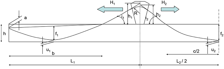
Figure 1. Extradosed cables reduced to single line.
Figure 1 also shows two values of the deviator height and a curvature radius. Concerning h1 and h2 these should be equal, unless the horizontal parts of the cable force is unbalanced. The latter introduces a bending moment on the beam. However, this bending moment proves to be rather moderate (Van Bogaert, 2006). In the present study, unbalanced horizontal forces are not considered.
If the cable is balanced, the slopes are equal and
In addition, Figure 1 shows the curvature of the cable at the location of the deviator. It may be noticed that, provided the curvature of the cables is limited, no saddle is needed and the cable ducts can be encased in the concrete member. The minimum radius for this deviation equals R = 3 m and has been obtained from suppliers. In addition, at both ends of this curved part of the cables, a minimum straight cable section must be provided. This ensures that no local bending of the cables will arise.
The effects of the extradosed prestress in the beam is identified to a system of external loads as shown in Figure 2 (Hambly, 1991). At the beam ends a compression force P is acting. Since the cable shows a slope angle θ with respect to a horizontal line, P has horizontal and vertical parts according to:
The slope θ is generally low, allowing to replace this by Ph = P and Pv = P tan θ. These forces do not act at the center of gravity of the end cross-section, thus introducing and moments MP
zc being the location of the gravity center. In addition to this and if the cable slopes i1 and i2 are unequal, additional bending moments Mtss will appear at the deviators
The most important effect of the prestress force is the uplifting pressures p1 and p2 marked in the figure and equalling:
Since the curve of the prestress cables is a second-degree parabola, the radius of curvature is constant. The values of p1 and p2 can thus be found from
The former equations have been used throughout the present study. The effect of external prestress forces has been introduced in calculations through the slope deflection method.
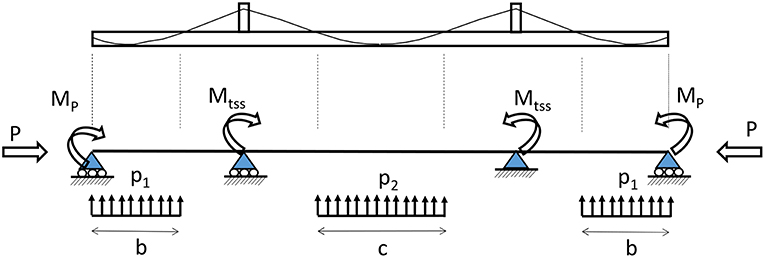
Figure 2. Effect of prestress as external loads.
Equation Results
It is useful to show an example of envelope curve for movable loads, in this case LM 1 according to EN 1991-2. The case shown in Figure 3 concerns a bridge with spans of 25, 50, and 25 m. At first glance, it may be assumed that the central span maximum moment would be smaller than the transition moment at the deviator. However, because of the variable character of loads, the central span moment is some 7–8% larger. This is not only the case for the dimensions considered but applies generally if the approach span is half the length of the central span. In addition, since at the intermediate supports the normal cross-section is reinforced by the deviator, which is an integral part of the beam, it may already be concluded that this particular location may not be the most critical one. This should be kept in mind while interpreting the results more in detail.
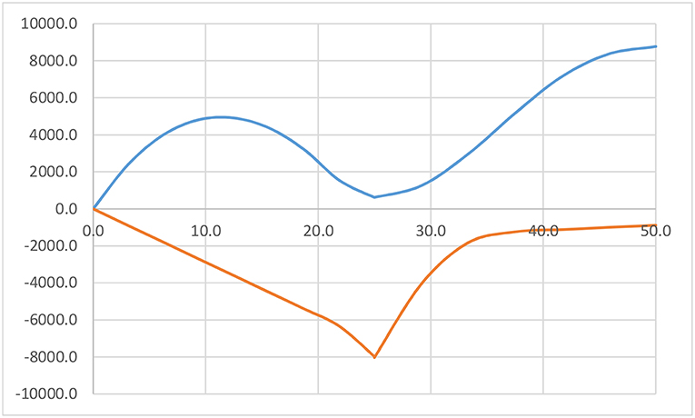
Figure 3. Envelope curve variable load.
The calculation strategy is now to choose various extradosed cable combinations in number and in cross sectional area. For each combination of prestress, the beam height may be varied and for every value of this height, the deviator height is varied. During this process all relevant parameters are varied, the results allowing to derive optimum solutions in terms of the required prestress. The outcome are values of concrete stresses, to be compared to the criteria mentioned in section Conditions.
Figure 4 shows a calculation result from this process concerning the main span center. For a given value of the beam height and cable system, the deviator height is varied. Four types of concrete stresses are indicated. These are the upper side stress for the maximum and minimum values of the bending moment and similar values for the lower side stress. Obviously, the upper stress for minimum bending moment and the lower side stress for maximum bending moment mostly render positive or tensile values. The aim must be to obtain equal values and thus minimum tensile stress. Hence the intersection of both lines should render the optimum value of the deviator height. This intersection also corresponds to the crossing of both compression lines being the upper side stress for maximum moment and the lower side stress for minimum bending. Hence, an optimum value of the deviator's height can be found.
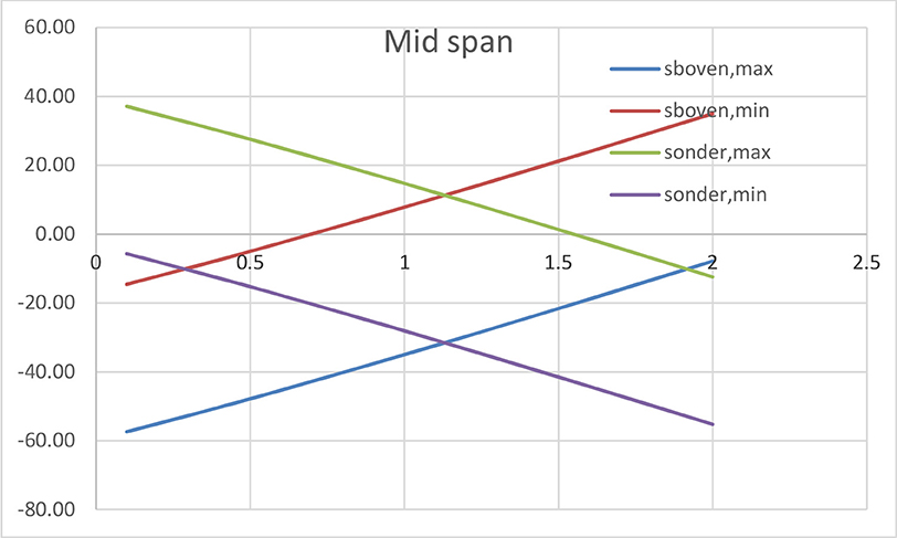
Figure 4. Concrete stresses as a function of deviator's height.
This optimum can also be derived from the condition:
If Mmax and Mmin are the maximum and minimum values of the bending moments, I the moment of inertia, a the distance from the upper side to the center of gravity of the cross section, b the distance from lower side to the gravity center, Ac the cross-section area and X the prestress force, the former equation becomes:
Or:
If the cross section is symmetrical and a = -b this reduces to
This simple relation can be translated as the bending moment due to prestress should equal the opposite of the average value of maximum and minimum bending moments due to all effects except the prestress. Clearly the value of the prestress force does influence this equation directly, although there is a linear relation to Mx.
Once the optimum value of the deviator height is found, an important issue is appearing. Whatever combination has been considered, the intersection of lines of σc, up, min and σc, low, max appears always to be in the tensile part of the diagrams. This means that any form of extradosed posttensioning is not capable of eliminating tensile concrete stress. Consequently, extradosed posttensioning necessarily must be supplemented with additional compression. The simple cause for this is the wide concrete stress variation due to Mmax and Mmin. Extradosed posttensioning can very well-counteract bending and tensile stress, provided the compression part is sufficiently large to resist the stress variations due to variable loads.
The additional compression is mostly provided by central prestress. Hence, additional prestress is inserted on both sides of the extradosed cables as shown in Figure 5. As most of the cross section is already occupied by the extradosed cables, the additional prestress must be symmetrical and the beam should accommodate the connected anchorage. It may be useful to also provide a waving course for the additional prestress, even counteracting the extradosed cables (Figure 6). However, this seems illogical, unless the height of the deviator should be increased for aesthetical reasons. Consequently, this study has concentrated on straight and central additional cables.
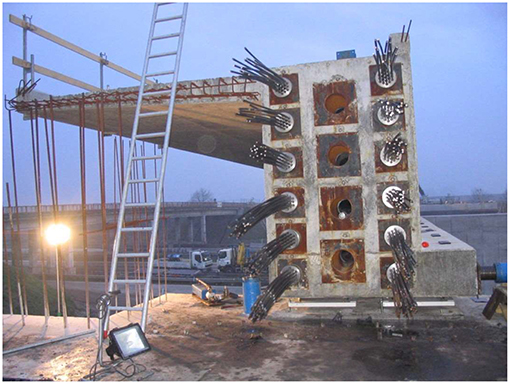
Figure 5. Additional central prestress.

Figure 6. Counteracting additional prestress.
The former applies to the central span. Other sections are equally important, the most evident one being the deviator section. Since the support cross-section has a larger inertia than current sections, it rarely is a critical location. In addition, as the bending moment rapidly decreases from the support section toward the span center, the bending at the first critical section is already lower. In addition, the width of the bearing itself, flattens out the bending moment. Figure 7 shows both the deviator and the bearing below.
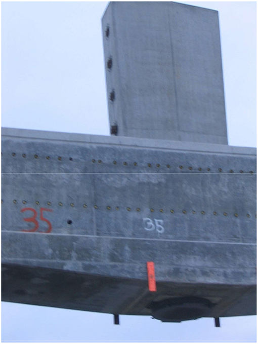
Figure 7. Deviator member.
The diagram of Figure 8 shows the ratio of the total bending moment at the support section vs. the moment at mid span for values of the latter varying from 40 to 80 m as a function of the ratio L1/L2. As this ratio increases, the relative magnitude of the bending moment at the support increases. The latter can be noticed especially as L1/L2 approaches 1. The graph also demonstrates also that the ratio under consideration increases with the size of the bridge. From a series of practical cases, the reduction of the peak bending moment at the first critical cross-section near the support has been found as 9.4%. This value may be different for particular cases, albeit it may serve as a reliable approximation. Hence, in view of the graph of Figure 8, the conditions for the span center may be applied if the ratio L1/L2 is lower than 0.6. This already covers a wide range of applications.
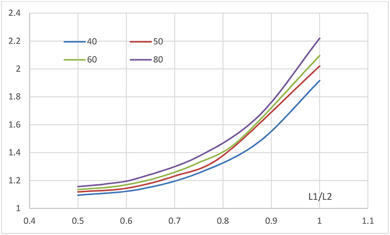
Figure 8. Total bending moment support section vs. span center.
Should this condition not be satisfied, the location of intersecting curves (as in Figure 3) for both the span center and the support have been compared. Firstly, in the many combinations examined, about half of the number does not have an intersection point. This means, there is no valid solution for the combination of extradosed prestress beam dimensions and the value of h1. The fraction of about 50% is without further meaning. Those combinations rendering an intersection of the curves σc, up, min and σc, low, max have been assembled both for the central span and the support section. In total 26 cases resulting in intersections of the curves have been used in this research.
In Figure 9 the evolution of the intersection points for the span center and the support section can be seen for a number of 20 cases calculated. The graph clearly shows that for low values of h1 both values are roughly identical, whereas if h1 increases it becomes larger near the supports. On average the ratio of h1 at the span center to the value at the support equals 1.077, which is a moderate difference.
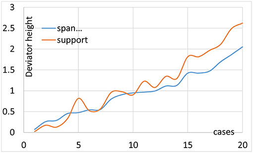
Figure 9. Variation of intersection points.
All other sections are less critical. Since it was shown that extradosed prestress cannot be separated from additional centered prestress, the conditions from 2.2 are automatically satisfied.
Stepwise Solution
In this section, the stepwise process to determine the dimensions of the prestressed members and of the cable curve is demonstrated, through an example of a 2-lane carriage road bridge with 3 spans of 40–80–40 m. The various steps are summarized in Table 1 and commented below. In each step the height of the cross section is chosen. In the present case rectangular cross-sections are used, although it is easily transformed to box section girders.
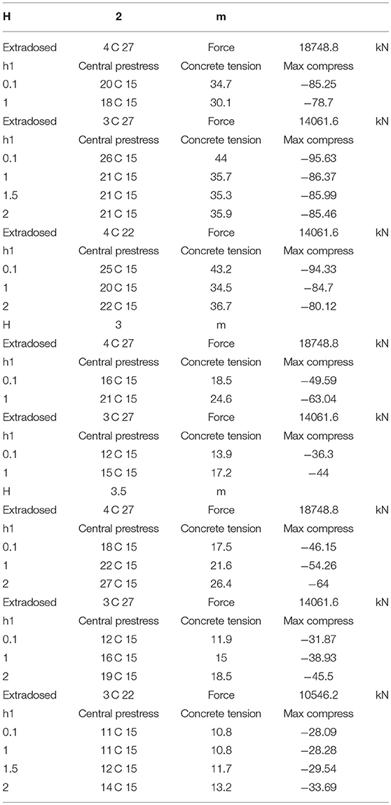
Table 1. Stepwise process to determine the dimensions of the prestressed members and of the cable curve.
The table starts by choosing an optimistic value of the girder height = 2 m. Subsequently a number and type of extradosed cables is chosen, in the first approximation 4 cables T27. The prestress force is then derived. For various values of the deviator height h1, the program returns maximum tensile concrete stress and how to counteract the latter by adding central prestress. For instance, the first value of h1 returns that 20 cables are to be installed as central prestress, since the concrete tension would reach 34.7 MPa. The added compression will generate maximum compression up to 85.25 MPa. Obviously, this combination is unacceptable, the central prestress being excessive as well as concrete compression, that for C 50/60 should be lower than 0.6 fck = 30 MPa.
The process is repeated several times. In the same case, increasing h1 does not solve the problem, since the concrete tensile stress does not lower in a significant way. However, the extradosed prestress may be in excess. Hence, in the following lines the cable system is reduced to 3 cables T 27. Clearly this does not help much since for various values of h1 the required central prestress is increased. This also applies to the maximum compression. We can note that increasing of the deviator height slightly decreases the concrete tensile stress. The latter also applies for lower values of the extradosed prestress of 3 cables T22.
Hence the girder height is insufficient, as could be expected. The table then resumes calculations with girder height of 3 m. Intuition can underpin this, since the ratio of maximum span to girder height then equals 26.7 still a slender value. Extradosed prestress of 4 cables 27 T and low deviator height of 0.1 m renders concrete tension of 18.5 MPa, easily compensated by 16 cables T 15, the final concrete compression reaching as high as 49.6 MPa. Should the deviator have average height of 1 m, concrete tension increases to 24.6 MPa and the final compression being 63 MPa. Hence, increasing the deviator height does not improve the results and the extradosed prestress is too large. Lowering this type of prestress to 3 cables T 27 still does not solve all issues.
Therefore, the beam height is increased to 3.5 m or slenderness of 22.86. Extradosed Prestress of 4 and 3 cables T 27 have been tried out, proving the amount of prestress is excessive. A moderate amount delivered by 3 cables T 22 renders acceptable combinations. Especially the deviator height of 1.5 m seems close to the optimum solution, since concrete tensile stress is limited to 11.7 MPa and may be counteracted by 12 cables of 15 strands central prestress. After applying the latter, concrete compression reaches 29.54 MPa, below the maximum value of 30 MPa. This combination may be preferred, since the central prestress is useful during launching.
These comments clearly demonstrate the iterative process can reach acceptable solutions in little time and requiring small effort. Few trials immediately result in acceptable combinations.
Construction by Launching
Since the aim is to reduce the number of anchors and to foster continuous prestress, construction by launching is an excellent choice. However, the incremental character, as considered for the launching of box girder bridges or sometimes for cable stayed structures, does not comply with the basic idea and requires many shorter prestressing cables and a multitude of anchors. Hence, launching as a whole seems the basic option. There is an overwhelming amount of literature, both scientific and practical, concerning construction by launching. In particular, cable schemes, jacking and the launching nose have been thoroughly described. These results have been used in the following.
Launching as a Single Structure
Launching proves to be easier for a multiple-span viaduct than for a three-span bridge, especially if the central span is much larger than the approach spans. Only few cases have considered launching from both sides and subsequent connecting the superstructure at this critical cross-section. The most appropriate process would be to construct the entire superstructure on one side of the subjacent obstacle and to launch in a single process. This inevitably requires using a launching nose, thus reducing the cantilevering bending at the first pier section. Literature indicates (Marchetti, 1984; Rossignoli, 1999; Wang et al., 2010) that the optimum length of the nose equals 0.6-times the span length, in case of equal spans. This does not necessarily apply to three-span bridges.
Considering Figure 10 the aim is to determine the nose length in such a manner that the cantilevering bending moment at section Introduction before reaching support 0 (upper part of Figure 10) would equal the bending moment at support 1 at the instant the concrete superstructure has reached support 0 (lower part of Figure 10). As the picture already mentions, an auxiliary counterweight W can be used. This weight may be adapted during the launching process. The dead weight of the concrete structure is indicated as g (kN/m) and the weight of the launching nose equals g1, its length being βL2. The cantilevering bending moment equals
Whereas, the bending moment at the support equals
In the case of 3-span bridges the equalizing of both quantities does not seem to be realistic. This is demonstrated in Figure 11 as a function of the value of β for a 25–50–25 m span bridge. Both curves do not intersect, even if β = 1. Consequently, there is no “best” choice for the length and characteristics of the launching nose (shown in Figure 12), the cantilevering bending moment being the largest value at all times.
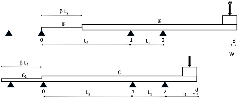
Figure 10. Launching schemes.
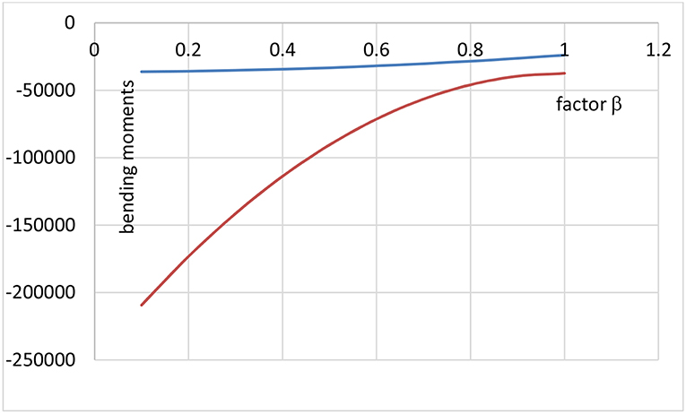
Figure 11. Cantilevering bending moments as a function of β.
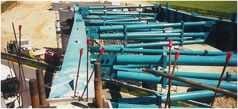
Figure 12. Launching nose.
In addition, the counterweight W should not exceed a maximum value, to prevent uplift at support 1. This maximum value can be derived from
A minimum value of the counterweight, ensuring positive reaction at support 2 is seldom of significance
Concerning the cantilevering bending moment M1' it may be noticed the curve is almost a second-degree parabola. This means, an increase of β has large consequence for low value, the effects decreasing if the parameter is already large. In this sense, and depending on the cost, reasonable values of the parameter are around 0.6–0.7. In the case, shown in Figure 11 the parameter equalled 0.6. The equation for M1'may provide guidance in determining the required resistance during launching.
Launching the entire superstructure seems in opposition to the fundamental idea of incremental launching as developed and applied now for several decades. However, it does not necessarily include the use of long formwork. The structure may still be cast in successive stages, provided a sliding formwork is used, which is moved in the sense downstream to the actual launching. Obviously, a disadvantage of launching as a whole, lies in the fact that it requires sufficient space upstream of the final location of the bridge. Should such space be unavailable, other alternatives must be considered.
In the former it was not mentioned how the launching actually is carried out. In most recent cases, prestress is used to pull the superstructure, finding the necessary reaction at one abutment. This implies this type of prestressing aid must have a length equalling at least the length of the bridge superstructure, although there is no need for rearranging the anchors. However, the length of the cables may become a determining factor in the total cost.
It must be stressed that many extradosed bridges, built as a whole, are transported to the final location by using SPMT's or self-propelled modular transporters. These engines have become viable and allow short distance transport of heavy building elements. However, their use across waterways is limited, unless pontoons are used to bring them from one bank to the other.
Launching From Both Sides
Launching from both sides is another option, requiring the connection of both parts at the center of the structure. The use of a launching nose then becomes immaterial. The connection at the center becomes a delicate work. In precast construction, short sections may be joined effectively, without additional concrete to fill the joint, provided pot and cam connections between the segments are used. Shrinkage-poor concrete including fine granular parts can be an option. Either a sufficiently large period must be provided to reduce shrinkage, or the effect must be included in the magnitude of prestress. Obviously, the latter is rather uncertain, since the joint is really small, compared to the rest of the structure. Practically, the shrinkage effect is too low to actually control it.
The same applies to creep due to prestress and dead load. The joint being small compared to the entire length, the effect is rather low and thus difficult to control. Calculating this effect results in variations below any reasonable influence. However, the connection remains a fragile point and just making it an attention point during building is insufficient as a conceptual measure. Therefore, various research programs have concentrated on the use of different types of resins or polymer-based filling mortars.
In addition, the continuity of cable ducts is of paramount importance. In addition, the connection between ducts must be sealed, in order to allow injection. However, the cables used for extradosed prestressing generally are of the non-adhesive type, protected by resin or wax and do not require post-tensioning injection. This type of cable gives more guarantee to obtain straight form of the exterior part of the cables. The stress distribution in concrete, due to the joint and tolerances of the cable duct positioning may be different from current sections. In particular tensile parts may appear. These local effects do not affect the general load carrying capacity of the structure.
Launching from both sides also introduces a cantilevering bending moment at the piers, similar to the previous equation, that now reduces to
Which is considerably lower than the former expression but does exceed the value of M1. In addition, for this system, the deformation of the cantilevering part takes high values. Using the same symbols as before, the sag at the joint between two halves takes the value of
Depending on the age and quality of the concrete and the exact dimensions of the cross-section, y may take values larger than L2/50. This requires rotating both joining parts as rigid bodies to close the rotation angle of both sides. Such a process can be easily done by jacking the pier supports or by lowering the abutments.
Consequently, launching two halves of the superstructure is a rather complicated and delicate process, involving several pitfalls and additional operations. The main issue concerns correct closing of the joint, by controlling and adjusting deformation, assuring homogeneous filling of the joint and providing perfect continuity of the cables. Therefore, in the framework of the present study, it is not considered further.
Launching With Temporary Reinforcement
An interesting building feature is shown in Figure 13. In this case a shallow box girder is being launched. Since the superstructure has insufficient stiffness as well as resistance, a vertical concrete rib has been added. After launching the rib is sawn off with diamond chord, leaving no further trace and a smooth cutting surface. Obviously, the rib may conflict with deviation members, but the latter can easily be constructed after launching of the superstructure and before installing the extradosed prestress.
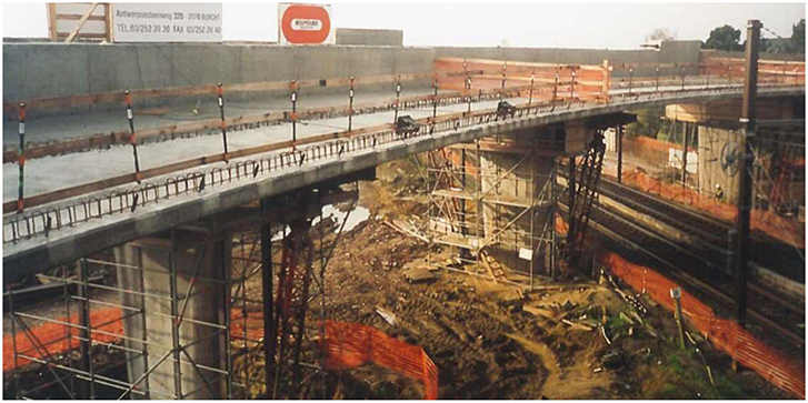
Figure 13. Reinforcing rib.
The use of a reinforcing rib also allows the alternative to launch the superstructure either with central prestress or no prestress at all. In the latter case sufficient normal reinforcement has to be provided. Since the cantilever position is the most critical, the reinforcing rib should allow resisting the cantilever moment setting β = 0. Obviously, takes large values and the combination of the reinforcing rib and a launching nose may be the best option to reduce this bending moment. Once the launching is finished and the rib is cut, the effect of central prestress suddenly modifies. For this reason, the option of not using any prestress seems preferable.
Reinforcing ribs can be used for box girder sections and for separate beams. In the latter case, each lateral beam must be equipped with a rib. Inevitably, this multiplies the number of construction stages.
Aligning Both Conditions
Strength Condition
Having verified the final situation of the prestressed members, and since the extradosed cables are not activated during previous steps, the central prestress should resist any temporary situation. It is easily verified, whether during launching the concrete stress complies with the condition. Resuming the case of 3.3, launching as a whole will cause a bending moment 224000 kNm. This is far too large to allow launching in these conditions. However, reinforcement by a rib and a launching nose may be considered.
If a launching nose, corresponding to β = 0.5 is considered, which is already an impressive auxiliary structure, the cantilevering moment reduces to 90480 kNm. For a rectangular cross-section, the latter implies bending tresses of 29.19 MPa. The centered prestress of 12 cables of 15 strands already delivers a concrete compression of 11.7 MPa. Since a rib of 2.1 * 0.3 m can be added, the concrete section resistance can easily be further increased and a workable combination can be achieved. However, this does not imply that deformations are also acceptable.
Deformations
As mentioned before, during launching, deformations may become too large to enable reaching a following pier. Rigid body rotation may compensate partly this issue, although acceptable limits must be observed. The rigid body rotations also require readjusting to normal level of the supports, which may be overlooked, or introduce large horizontal force on the pier heads.
Figure 14 shows the deflections at the tip of the superstructure, launched as a whole, or of the launching nose, before reaching the next pier and having crossed the larger central span. If no particular device is used, or any reinforcement is applied, the deflections are unacceptable, especially for large spans. However, if a launching nose of 0.5-times the central span length is used, the deflection is reduced to on average 40% of the first value. Should a rib reinforcement be preferred, the knock down factor equally reaches on average 40%. The largest efficiency is obtained by combining both auxiliary equipments, since the deflections are reduced to 20% on average. In addition, the absolute value has become acceptable for rigid body rotation or for the nose being lifted as it reaches the next pier. From this diagram, we may conclude that launching as a whole, using both ribs and nose, is an acceptable option, provided the central span is limited to 60 m. For larger span, the option of SPMT transport is probably more recommendable.
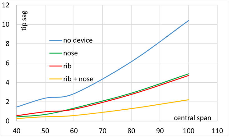
Figure 14. Tip deflections during launching.
Amount of Prestress Steel
The amount of prestress steel, both the extradosed and the centered parts have been determined for 3-span bridges, varying from 40 to 100 m central span. The amount of extradosed prestress is on average 45% of the centered prestress. Hence, the first quantity is definitely lower than the compensating straight cables. This indicates that extradosed prestress is in aiding to compensate the variable stresses due to live loads, rather than a basic system. This confirms the character of this type of structures, which remains principally a prestressed concrete girder system, rather than a cable-supported one.
In addition, the geometric amount of prestress divided by the cross section reaches on average 1.55%. Smaller spans require a somewhat higher percentage. This is due to the trend of choosing smaller girder depth for smaller span. However, the variations of the prestress percentage are rather small. For higher span the extradosed prestress becomes more important and the amount of prestressing steel decreases. Hence, extradosed bridges may become more interesting for higher span than 100 m, but there is a need to change the system to a hybrid structure.
Conclusions
It was implied that classical extradosed prestress, which is simply a prestressed beam, including deviators instead of pylons and supported by bearings, are a well-functioning system for medium span bridges. In particular, the advantage of the system follows from the reduction of the number of anchors and the continuity of the prestressing cables.
In this type of bridge superstructure, the extradosed prestress must be supplemented by centered or counteracting additional prestress, since the variation of concrete stresses causes tension. The alternative of centered prestress may be preferred since the friction loss is low and its continuous character allows limitation of the number of anchors.
The concrete stress conditions for upper and lower side of the cross-section show an intersection point as a function of the deviator height. These intersection points are somewhat different, but quite similar, for the mid-span section and for the deviator location, thus rendering the optimum deviator height. This condition allows determining the latter characteristic parameter for extradosed prestress.
The construction of these bridges by launching as a whole is possible, provided reinforcement of the superstructure by ribs and using launching noses. However, this process applies only if the central span is lower than 60 m. Beyond this limit, other construction methods must be considered as for example the use of SPMT transport devices.
The relative total amount of prestress or geometric percentage in extradosed bridges is rather constant, as is the fraction of the extradosed to the total prestress. For higher span the extradosed prestress becomes more important and the amount of prestressing steel decreases. Nevertheless, the auxiliary centered prestress takes the largest part in the total amount, thus confirming the character of this type of structures, which remains principally a prestressed concrete girder system, rather than a cable-supported one.
Author Contributions
All authors listed have made a substantial, direct and intellectual contribution to the work, and approved it for publication.
Conflict of Interest Statement
The authors declare that the research was conducted in the absence of any commercial or financial relationships that could be construed as a potential conflict of interest.
References
Cheng, C. (2012). Optimization for cable-force of extradosed cable-stayed bridges based on minimal cost principle. Eng. Mech. 29, 141–146. Available online at: http://engineeringmechanics.cn/EN/abstract/abstract5626.shtml
De Pauw, B., and Van Bogaert, P. (2013). “New continuous 3-span concrete railway decks with extradosed post-tensioning cables in widening an existing multiple arch bridge,” in IABSE Symposium Report Assessment, Upgrading and Refurbishment of Infrastructures (Rotterdam), 566–567.
Kim, H. K., Lyoo, J. K., Ahn, Y. K., and Cheong, J. K. (2012). “Geum-gang 1st bridge – Extradosed bridge with V-shape pylon,” in IABSE Congress Report 18th Congress of IABSE (Seoul), 2067–2073.
Lin, P., Liu, F., Zhou, S., and Liu, S. (2007). Mechanical characteristics and defining of extradosed bridges. J. China Railway Soc. 29, 136–140. Available online at: http://open.oriprobe.com/articles/12094561/Mechanical_Characteristics_and_Defining_of_Extradosed_Bridges.htm
Lynn Stroh, S. (2012). On the Development of the Extradosed Bridge Concept. Dissertation master University of South-Florida, Tampa, FL.
Marchetti, M. E. (1984). Specific design problems related to bridges built using the incremental launching method. Eng. Struct. 6, 185–210. doi: 10.1016/0141-0296(84)90046-4
Mathivat, J. (1989). Conception et evolution des ouvrages d'art en béton précontraint en France. Rept Journée Belge du Béton. Ghent. IV, 1–16.
Meng, X., and Zhang, C. (2014). Extradosed and intradosed cable-stayed bridges with continuous cables: conceptual consideration. J. Bridge Eng. 19, 5–14. doi: 10.1061/(ASCE)BE.1943-5592.0000477
Peng-guihan Wang-wetao, C.-B. (2006). Bridgescape design of extradosed bridge. Fujian Archit. Constr. 3.
Saad, F. (2004). “Structural optimization of extradosed bridges,” in IABSE Symposium Report Metropolitan Habitats and Infrastructure Symposium Shanghai (Shanghai), 212–223.
Van Bogaert, P. (2006). “Anchoring of cables for single pylon extradosed post-tensioned concrete bridge,” in Proceedings of the 2nd FIB Congress (Naples: University of Naples Federico II).
Wang, W., Zheng, H., and Zeng, X. (2010). Optimum design of launching nose during incremental launching construction of same-span continuous bridge. World Acad. Sci. Eng. Technol. Int. J. Struct. Constr. Eng. 4, 420–425. Available online at: https://waset.org/publications/10469/optimum-design-of-launching-nose-during-incremental-launching-construction-of-same-span-continuous-bridge
Wei, C., Chen, H., and Wang, Y. (2007). Parameters' sensitivity analysis of extradosed cable-stayed bridge. J. Zhengzhou Univ. Nation Sci. Ed. 39:178. Available online at: http://open.oriprobe.com/articles/18813876/Parameters__Sensitivity_Analysis_of_Extradosed_Cable_stayed_Bridge.htm
Keywords: extradosed prestress, concrete bridges, minimizing anchors, continuous prestress, bridge launching
Citation: Van Bogaert P and De Backer H (2019) Continuous Prestress in Launched Extradosed Bridges. Front. Built Environ. 5:81. doi: 10.3389/fbuil.2019.00081
Received: 01 November 2018; Accepted: 03 June 2019;
Published: 19 June 2019.
Edited by:
Joan Ramon Casas, Universitat Politecnica de Catalunya, SpainCopyright © 2019 Van Bogaert and De Backer. This is an open-access article distributed under the terms of the Creative Commons Attribution License (CC BY). The use, distribution or reproduction in other forums is permitted, provided the original author(s) and the copyright owner(s) are credited and that the original publication in this journal is cited, in accordance with accepted academic practice. No use, distribution or reproduction is permitted which does not comply with these terms.
*Correspondence: Philippe Van Bogaert, philippe.vanbogaert@ugent.be