Spatiotemporal Modeling of Lifting Task Scheduling for Tower Cranes With a Tabu Search and 4-D Simulation
 Keyi Wu
 Borja García de Soto
- 1School of Civil Engineering, Central South University, Changsha, China
- 2S.M.A.R.T. Construction Research Group, Division of Engineering, New York University Abu Dhabi (NYUAD), Abu Dhabi, United Arab Emirates
Effective lifting task scheduling for tower cranes is beneficial for the smooth operation of a construction project. Previous studies have often ignored workspace availability for lifting task scheduling. Consequently, the pre- and post-lifting processes that are primarily caused by material preparation and transfer times at supply and demand points were not considered. Therefore, an intuitive and effective way to display more element information of lifting tasks and more complex relationships among lifting tasks is required. To solve these problems, this study proposes a spatiotemporal modeling of lifting task scheduling for tower cranes, which consists of a lifting task scheduling optimization model with a tabu search and a lifting task scheduling display method with 4-D simulation. The concept of the proposed spatiotemporal modeling is demonstrated by an example with 28 lifting tasks and two tower cranes. The results show that the average total time of the optimized lifting task scheduling, taking into consideration the material preparation and transfer times at the supply and demand points, can be reduced by 25.82%. In addition, the element information and relationship of lifting tasks can be clearly presented using the proposed display method with 4-D simulation.
Introduction
In construction projects, tower cranes are typically used to lift heavy and bulky materials, such as rebar, structural steel, and formwork, and their lifting efficiency imposes a significant impact on the progress of construction projects (Shapira et al., 2007; Huang et al., 2011). Inappropriate lifting task scheduling for tower cranes not only negatively affects the completion of lifting tasks, but also causes delays in subsequent construction tasks (Monghasemi et al., 2016); in some cases, it can even change the critical path of a construction project, which ultimately leads to increased project time and cost (Zavichi and Behzadan, 2011). Traditional lifting task scheduling for tower cranes adopts the principle of first in, first served in practice; however, it may not be the optimal solution in terms of objective metrics, such as minimum total lifting time (Huang and Wong, 2018). It is beneficial for the smooth operation of a construction project to design appropriate lifting task scheduling for tower cranes. To that end, in recent years, researchers are paying attention to this domain due to the increase in the construction of large-scale projects with a large number of lifting tasks for tower cranes (Monghasemi et al., 2016; Ji and Leite, 2018).
Regarding lifting task scheduling for tower cranes, the time, assignment, and sequence of lifting tasks should be mainly taken into consideration.
For the time of lifting tasks, some applicable mathematical models have been proposed. According to the locations of tower cranes as well as supply and demand points, a model to calculate horizontal motion time for tower cranes with respect to a polar coordinate system was created (Rodriguez-Ramos and Francis, 1983). This model assumed two cases of simultaneous and consecutive motions for the trolley and jib of tower cranes and established the corresponding equations. Later, a model to calculate horizontal motion time for tower cranes with respect to a rectangular coordinate system was created, and it involved the degree of coordination between the radial motion for the trolley of tower cranes and the slewing motion for the jib of tower cranes in the horizontal plane (Zhang et al., 1996). On this basis, vertical motion time for tower cranes and degree of coordination between the horizontal and vertical motions as well as loading and unloading time of materials were further formulated into the model, which became an important model prototype (Zhang et al., 1999). Based on this model prototype, researchers made corresponding improvements according to specific considerations. For example, the total lifting time was multiplied by numerical parameters to account for lifting difficulties, waste, and contingency (Huang et al., 2011; Al Hattab et al., 2017, 2018); the variation on the hoist velocity of the hook of tower cranes due to the lifted load determined by the radius-load curve of tower cranes was considered (Abdel-Khalel et al., 2013; Abdelmegid et al., 2015); a safety distance of the vertical motion for tower cranes was included in order to prevent collisions with platforms to support materials (Huang and Wong, 2018); the increase of vertical motion time for tower cranes caused by obstacles between supply and demand points was added (Younes and Marzouk, 2018); and delay time to avoid collisions with other operating tower cranes were taken into account (Al Hattab et al., 2017, 2018; Younes and Marzouk, 2018).
For the assignment and sequence of lifting tasks, some specific strategies have been made. For example, a lifting task assignment model consisting of two criteria applied to measure assignment effectiveness was developed: one was balanced workloads in terms of respective lifting time for each tower crane, and the other was the lowest possibility of collisions among tower cranes (Zhang et al., 1999). In order to optimally assign lifting tasks in the common zone to overlapping tower cranes and maintain collision-free motion paths for tower cranes, a model using lookahead planning (LAP) and building information modeling (BIM) was employed (Al Hattab et al., 2017). Some researchers regarded the sequence problem of lifting tasks as the traveling salesman problem (TSP) and proposed an optimization problem in terms of the minimum total time of lifting tasks (Zavichi and Behzadan, 2011; Zavichi et al., 2014). Because the extreme pending time for a lifting task can hinder the progress of its subsequent construction tasks, a model for the sequence of lifting tasks was developed to balance the lifting and pending times of tasks (Monghasemi et al., 2016). In some cases, urgent lifting tasks require priority; thus, an optimization model for the lifting sequence to prioritize urgent tasks was created (Huang and Wong, 2018). In addition, the effects of different lifting task scheduling, including first in, first served; shortest job first; nearest neighbor first; and TSP, were also studied (Huang and Wong, 2018). To solve this scheduling problem, some optimization methods, such as meta-heuristic algorithms and mathematical programming, have been applied. For instance, an improved harmony search based on the power index method was used for the lifting sequence with the least deviation of pending time (Monghasemi et al., 2016), and a binary mixed-integer linear program with the branch-and-bound technique was used to minimize total lifting time (Huang and Wong, 2018).
The clear display of lifting task scheduling for tower cranes can help the project team perform lifting tasks accurately and identify potential lifting problems that are easy to overlook. In most construction projects, lifting task scheduling for tower cranes is typically displayed using the traditional Gantt chart. In recent years, with the development and popularization of visualization technology in the construction industry, 4-D simulation has been used to display lifting task scheduling for tower cranes because it can provide an easy and convenient way to understand lifting operations and processes (Al-Hussein et al., 2006; Ji and Leite, 2018). For example, a practical methodology for integrating 3-D visualization with special-purpose simulation (SPS) was presented, and an integrated system based on this methodology was built and could output a 4-D short-term schedule, simulation model, virtual reality model, animated lifting operation, etc. (Al-Hussein et al., 2006). Also, 4-D simulation was applied to validate the logic and setup of a lifting task scheduling model, identify spatial and capacity constraints for tower cranes, detect potential collisions among tower cranes during lifting tasks, analyze the utilization of each tower crane for balancing workload and planning deployment, simulate the tower crane operator's viewpoint, and so on (Irizarry and Karan, 2012; Wang et al., 2015; Marzouk and Abubakr, 2016; Sugimoto et al., 2016; Al Hattab et al., 2018; Ji and Leite, 2018).
Researchers have made many beneficial efforts in the domain of lifting task scheduling for tower cranes, but a limitation in most studies is that a lifting task only focused on the no-load and loaded lifting processes of tower crane motion and ignored the pre- and post-lifting processes of tower crane stops. In a lifting task, lifted materials should be sorted and stacked at the supply point before sending a lifting request to the tower crane operator during the pre-lifting process, and the lifted materials should be assigned and removed at the demand point after they are unloaded during the post-lifting process. Thus, the supply and demand points are inevitably occupied for a period of time to prepare and transfer the lifted materials. In this sense, lifting tasks cannot be performed continuously without stopping due to limited workspace. If lifting task scheduling ignores workspace availability, it results in potential workspace congestion at supply and demand points and negatively affects the flow of lifting tasks as well as related construction tasks. Therefore, the pre- and post-lifting processes, including material preparation and transfer times, should be considered in lifting task scheduling for tower cranes. Similar to the processes included in previous lifting task scheduling models, only no-load and loaded lifting processes were displayed with 4-D simulation in most studies, and the pre- and post-lifting processes were ignored. The addition of the pre- and post-lifting processes poses new challenges to the display of lifting task scheduling, and it would be beneficial to find an intuitive and effective method to display more element information of lifting tasks (e.g., tower cranes, supply and demand points) and more complex relationships among lifting tasks (e.g., working status of tower cranes, workspace availability of supply and demand points) with 4-D simulation.
Based on the background, this study proposes the spatiotemporal modeling of lifting task scheduling for tower cranes with a tabu search and 4-D simulation to solve the above problems. The remainder of the article is organized as follows. In section Methodology, the methodology of the study is presented. Section Spatiotemporal Modeling details the formulation of the spatiotemporal modeling. In section An Experimental Case Study, an example is used to illustrate the performance of the proposed spatiotemporal modeling. Section Discussion discusses the significance and weakness of the study. The conclusion is given in section Conclusion.
Methodology
The primary objective of this study is to develop and validate the spatiotemporal modeling of lifting task scheduling for tower cranes. The development of the spatiotemporal modeling consists of two parts: one part is a lifting task scheduling optimization model taking material preparation and transfer times at supply and demand points into consideration with a tabu search, and the other part is a lifting task scheduling display method with the normal- and fine-level schemes using 4-D simulation. The lifting scheduling for tower cranes refers to lifting tasks that are performed by assigned tower cranes in a specific sequence; therefore, it could be regarded as a production scheduling problem. The objective of the production scheduling problem is to find the optimal solution from feasible solutions in terms of set objective metrics (Samavati et al., 2017); in this study, the objective metrics of lifting task scheduling for tower cranes is the minimum total time because it is considered to be one of the most important evaluation criteria (Zavichi et al., 2014; Huang and Wong, 2018). In order to evaluate the total time of the lifting scheduling solution quantitatively, a lifting task time model is created, and material preparation and transfer times are specifically involved due to the consideration of workspace availability at supply and demand points. Because there is no polynomial algorithm for lifting task scheduling, namely it is an NP-hard problem, finding the optimal solution from massive feasible solutions costs a lot as the number of lifting tasks and tower cranes increases. The tabu search is a meta-heuristic algorithm inspired by the memory mechanism of human intelligence. It adopts tabu strategies to avoid detour search and introduces aspiration criteria to release good solutions for ensuring the effectiveness and diversity of the search process (Glover, 1986, 1989, 1990). The tabu search has been widely and effectively used in the field of scheduling optimization and shown good computational performance (Edwards et al., 2015; Abdelaziz and Mir, 2016; García de Soto et al., 2017); therefore, it is applied in this study. The hue and value are both the attributes of color, the hue refers to the appearance of color (e.g., red, green, blue), and the value refers to the brightness of color (e.g., dark red, medium red, light red) (Stuart et al., 2014; Logvinenko et al., 2015; Emery et al., 2017). Colors with different hues and values can convey information intuitively and effectively (Einakian and Newman, 2019), so it is combined with 4-D simulation to display lifting task scheduling for tower cranes, and schemes at different levels of detail are designed to meet the specific need of the project team. Finally, the proposed lifting task scheduling optimization model and display method are implemented in an experimental case study to verify their functionalities.
Spatiotemporal Modeling
This section presents the spatiotemporal modeling of lifting task scheduling for tower cranes. It is divided into two parts: the first part deals with the optimization of lifting task scheduling with a tabu search, and the second part addresses the display of lifting task scheduling with 4-D simulation, and they are explained as follows.
Lifting Task Scheduling Optimization Model With a Tabu Search
To find the optimal lifting task scheduling in terms of minimum total time, a lifting task scheduling optimization model with a tabu search is created. First, the notation used in the model is listed; then, a lifting task time model integrating the pre- and post-lifting processes is introduced, and finally, the alternative solution structure and the applied tabu search are detailed.
Notation
Indexes
x position at x-axis;
y position at y-axis;
z position at z-axis;
i lifting task;
i′ last lifting task of the tower crane performing lifting task i;
I number of lifting tasks;
j material;
k(k′) tower crane;
n′ last demand point;
m supply point;
n demand point.
Parameters
α degree of coordination of tower crane hook motion in the radial and slewing directions in the horizontal plane between 0 and 1; 0 represents simultaneous motion, and 1 represents consecutive motion;
β degree of coordination of tower crane hook motion in the horizontal and vertical planes between 0 and 1; 0 represents simultaneous motion, and 1 represents consecutive motion;
h safety distance for preventing collisions with platforms to support materials;
Sns neighboring solution size;
Stl tabu list size;
Imax maximum iterations.
Variables
, , coordinates of tower crane k;
, , coordinates of last demand point n′;
, , coordinates of supply point m;
, , coordinates of demand point n;
Vαk radial velocity of the trolley of tower crane k;
Vωk slewing velocity of the jib of tower crane k;
hoist velocity of the hook of tower crane k according to the quantity of material j;
maximum hoist velocity of the hook of tower crane k;
Nk current number of lifting tasks performed by tower crane k;
quantity of material j for lifting task i;
UTpj preparation time of unit quantity for material j;
UTtj transfer time of unit quantity for material j;
UTlj loading time of unit quantity for material j;
UTuj unloading time of unit quantity for material j;
Sc current solution;
last current solution;
Sμ optimal neighboring solution;
Sγ optimal neighboring solution that is not in the tabu list;
So current optimal solution;
Ic current iterations.
Functions
horizontal distance between tower crane k and last demand point n′ in the no-load process b of lifting task i;
horizontal distance between tower crane k and supply point m in the no-load process b of lifting task i;
horizontal distance between last demand point n′ and supply point m in the no-load process b of lifting task i;
angle between last demand point n′ and supply point m for the jib of tower crane k in the no-load process b of lifting task i;
additional distance over the obstacle between last demand point n′ and supply point m in the no-load process b of lifting task i;
radial motion time for the trolley of tower crane k from last demand point n′ to supply point m in the no-load process b of lifting task i;
slewing motion time for the jib of tower crane k from last demand point n′ to supply point m in the no-load process b of lifting task i;
horizontal motion time for the hook of tower crane k from last demand point n′ to supply point m in the no-load process b of lifting task i;
vertical motion time for the hook of tower crane k from last demand point n′ to supply point m in the no-load process b of lifting task i;
horizontal distance between tower crane k and supply point m in the loaded process c of lifting task i;
horizontal distance between tower crane k and demand point n in the loaded process c of lifting task i;
horizontal distance between supply point m and demand point n in the loaded process c of lifting task i;
angle between supply point m and demand point n for the jib of tower crane k in the loaded process c of lifting task i;
additional distance over the obstacle between supply point m and demand point n in the loaded process c of lifting task i;
radial motion time of the trolley of tower crane k from supply point m to demand point n in the loaded process c of lifting task i;
slewing motion time of the jib of tower crane k from supply point m to demand point n in the loaded process c of lifting task i;
horizontal motion time of the hook of tower crane k from supply point m to demand point n in the loaded process c of lifting task i;
vertical motion time of the hook of tower crane k from supply point m to demand point n in the loaded process c of lifting task i;
total time for lifting task i performed by tower crane k;
start time for lifting task i performed by tower crane k;
end time for lifting task i performed by tower crane k;
T total time for lifting task scheduling;
time for the pre-lifting process a of lifting task i performed by tower crane k;
time for the no-load lifting process b of lifting task i performed by tower crane k;
time for the loaded lifting process c of lifting task i performed by tower crane k;
time for the post-lifting process d of lifting task i performed by tower crane k;
preparation time for the pre-lifting process a of lifting task i performed by tower crane k;
delay time for the no-load lifting process b of lifting task i performed by tower crane k;
motion time for the no-load lifting process b of lifting task i performed by tower crane k;
delay time for the loaded lifting process c of lifting task i performed by tower crane k;
loading time for the loaded lifting process c of lifting task i performed by tower crane k;
motion time for the loaded lifting process c of lifting task i performed by tower crane k;
unloading time for the loaded lifting process c of lifting task i performed by tower crane k;
transfer time for the loaded lifting process d of lifting task i performed by tower crane k.
Lifting Task Time Model
The total time for lifting task i performed by tower crane k () is determined by the time for pre-lifting process (), no-load lifting process (), loaded lifting process (), and post-lifting process () as expressed in Equation (1).
If lifting task i is the first lifting task, the start time for lifting task i performed by tower crane k () is 0; if lifting task i is not the first lifting task, and the last lifting task of tower crane k performing lifting task i (i.e., lifting task i′) is the last lifting task of lifting task i (i.e., lifting task i − 1), the start time for lifting task i performed by tower crane k () is the maximum among the start time for available supply point m of lifting task i (), the start time for available demand point n of lifting task i (), and the end time for the loaded lifting process c of lifting task i′ performed by tower crane k (); and if lifting task i is not the first lifting task, and the last lifting task of tower crane k performing lifting task i (i.e., lifting task i′) is not the last lifting task of lifting task i (i.e., lifting task i − 1), the start time for lifting task i performed by tower crane k () is the maximum among the start time for available supply point m of lifting task i (), the start time for available demand point n of lifting task i (), the end time for the loaded lifting process c of lifting task i′ performed by tower crane k (), and the start time for the pre-lifting process a of lifting task i − 1 performed by tower crane k′ (). They are expressed in Equation (2).
The end time for lifting task i performed by tower crane k () is determined by its start time () and total time () as expressed in Equation (3).
Thus, the total time for lifting task scheduling (T) is the maximum end time among all lifting tasks (T1, …, Ti, …, TI) as expressed in Equation (4). The details of those four processes are explained as follows.
The first one is the pre-lifting process, and the time for the pre-lifting process a of lifting task i performed by tower crane k () is determined by the preparation time () as expressed in Equation (5).
The preparation time () is the time to sort and stack material j at supply point m, and it is determined by the quantity of material j for lifting task i () and the preparation time of unit quantity for material j (UTpj) as expressed in Equation (6).
The second one is the no-load lifting process, and the time for the no-load lifting process b of lifting task i performed by tower crane k () is determined by the delay time () and motion time () as expressed in Equation (7).
The delay time () is the time to wait for avoiding collisions with other operating tower cranes during the no-load process b of lifting task i. If the time when tower crane k can start the motion () is equal to the end time for the pre-lifting process (), the delay time () is equal to 0, and if the time when tower crane k can start the motion () is later than the end time for the pre-lifting process (), the delay time () is equal to the difference between them as expressed in Equation (8).
The motion time () is the time for the hook of tower crane k (, , ) from the last demand point n′ (, , ) to supply point m (, , ). If the current number of lifting tasks performed by tower crane k (Nk) is 0, the motion time () is equal to 0; if the current number of lifting tasks performed by tower crane k (Nk) is >0, and the last demand point n′ and supply point m are common, the motion time () is equal to 0; and if the current number of lifting tasks performed by tower crane k (Nk) is >0, and last demand point n′ and supply point m are not common, the motion time () is determined by the horizontal () and vertical () motion times for the hook of tower crane k as well as the degree of coordination between them (β). They are expressed in Equation (9). In the horizontal plane, the radial motion time for the trolley of tower crane k () and the slewing motion time for the jib of tower crane k () are calculated using Equations (10) and (11), respectively. The horizontal motion time for the hook of tower crane k () depends on these two times as well as the degree of coordination (α) between them as expressed in Equation (12). The horizontal distance between tower crane k and last demand point n′ (), the horizontal distance between tower crane k and supply point m (), and the horizontal distance between last demand point n′ and supply point m () are calculated using Equations (13), (14), and (15), respectively. The angle between the last demand point n′ and supply point m for the jib of tower crane k () is calculated using Equation (16). In the vertical plane, the vertical motion time for the hook of tower crane k () is calculated using Equation (17). The vertical motion distance involves the vertical distance between last demand point n′ and supply point m (), the safety distance for preventing collisions with platforms to support materials (2h), and the additional distance over the obstacle between the last demand point n′ and supply point m (). The hoist velocity of the hook of tower crane k is at its maximum ().
The third one is the loaded lifting process, and the time for the loaded lifting process c of lifting task i performed by tower crane k () is determined by the delay time (), loading time (), motion time (), and unloading time () as expressed in Equation (18).
The delay time () is the time to wait for avoiding collisions with other operating tower cranes during the loaded process c of lifting task i. If the time when tower crane k can start loading () is equal to the end time for the no-load lifting process (), the delay time () is equal to 0, and if the time when tower crane k can start loading () is later than the end time for the no-load lifting process (), the delay time () is equal to the difference between them as expressed in Equation (19).
The loading time () is the time to load material j at supply point m, and it is determined by the quantity of material j for lifting task i () and the loading time of unit quantity for material j (UTlj) as expressed in Equation (20).
The motion time () is the time for the hook of tower crane k (, , ) from supply point m (, , ) to demand point n (, , ), and it is determined by the horizontal () and vertical () motion times for the hook of tower crane k as well as the degree of coordination between them (β) as expressed in Equation (21). In the horizontal plane, the radial motion time for the trolley of tower crane k () and the slewing motion time for the jib of tower crane k () are calculated using Equations (22) and (23), respectively. The horizontal motion time for the hook of tower crane k () depends on these two periods as well as the degree of coordination (α) between them as expressed in Equation (24). The horizontal distance between tower crane k and supply point m (), the horizontal distance between tower crane k and demand point n (), and the horizontal distance between supply point m and demand point n () are calculated using Equations (25), (26), and (27), respectively. The angle between supply point m and demand point n for the jib of tower crane k () is calculated using Equation (28). In the vertical plane, the vertical motion time for the hook of tower crane k () is calculated using Equation (29). The vertical motion distance involves the vertical distance between supply point m and demand point n (), the safety distance for preventing collisions with platforms to support materials (2h), and the additional distance over the obstacle between supply point m and demand point n (). The hoist velocity of the hook of tower crane k () is determined based on the quantity of material j for lifting task .
The unloading time () is the time to unload material j at demand point n, and it is determined by the quantity of material j for lifting task i () and the unloading time of unit quantity for material j (UTuj) as expressed in Equation (30).
The last one is the post-lifting process, and the time for the post-lifting process d of lifting task i performed by tower crane k () is determined by the transfer time () as expressed in Equation (31).
The transfer time () is the time to assign and remove material j at demand point n, and it is determined by the quantity of material j for lifting task i () and the transfer time of unit quantity for material j (UTtj) as expressed in Equation (32).
Tabu Search
The alternative solution structure is illustrated in Figure 1. If there is only one tower crane in the construction project, Figure 1A is used; otherwise, Figure 1B is used. In Figure 1A, the numbers in the blocks represent the numbers of lifting tasks, and the sequence of the numbers means the sequence in which the corresponding lifting tasks are performed, namely lifting tasks 3, 7, 6, 1, 8, etc., are performed sequentially. In Figure 1B, the numbers in the odd blocks represent the numbers of lifting tasks, and the sequence of the numbers means the sequence in which the corresponding lifting tasks are performed, namely lifting tasks 5, 2, 3, etc., are performed sequentially; the numbers in the even blocks represent the numbers of tower cranes, and the sequence of the numbers means the sequence of the corresponding performing tower cranes, namely lifting tasks 5, 2, 3, etc., are performed by tower cranes 3, 1, 2, etc., respectively.
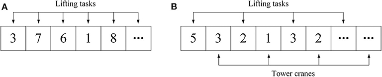
Figure 1. Illustration of the alternative solution structures in the cases of single (A) and multiple (B) tower crane(s).
The procedure of the applied tabu search, which is shown in Figure 2, has the following nine steps.
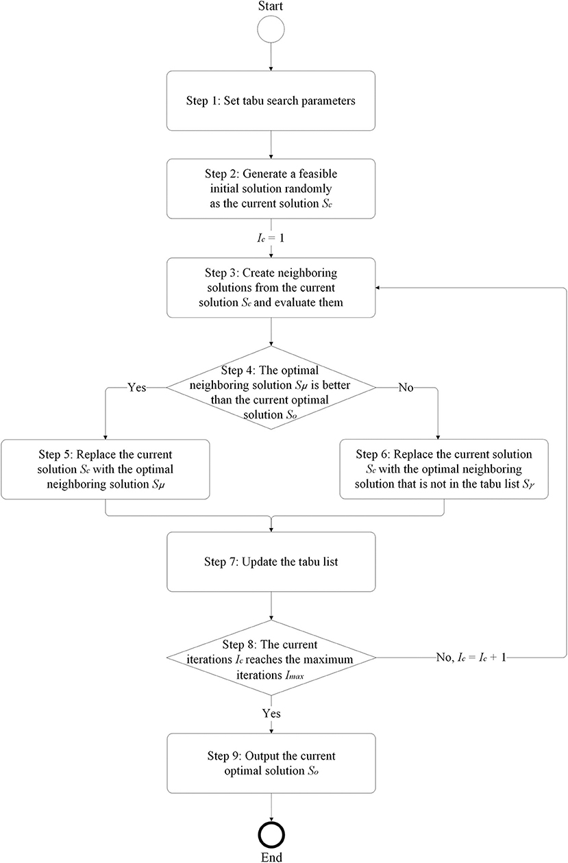
Figure 2. Procedure of the applied tabu search.
Step 1: Set tabu search parameters. They are the neighboring solution size Sns, tabu list size Stl, and maximum iterations Imax.
Step 2: Generate a feasible initial solution randomly as the current solution Sc. The feasible solution means that the load and location of each lifting task are within the capacities of the performing tower crane.
Step 3: Create neighboring solutions from the current solution Sc and evaluate them. For the creation of neighboring solutions, select a block of the current solution randomly first, if a lifting task is selected, then select another lifting task randomly and exchange the sequence between the two lifting tasks, and if a tower crane is selected, then replace the tower crane with a different tower crane selected randomly.
Step 4: If the optimal neighboring solution Sμ is better than the current optimal solution So, go to Step 5; otherwise go to Step 6.
Step 5: Replace the current solution Sc with the optimal neighboring solution Sμ and go to Step 7.
Step 6: Replace the current solution Sc with the optimal neighboring solution that is not in the tabu list Sγ and go to Step 7.
Step 7: Update the tabu list. If the current solution Sc is the current optimal solution So, add the last current solution to the tabu list; otherwise, add the current solution Sc to the tabu list. If the number of solutions in the tabu list is less than tabu list size Stl, add the solution to the tabu list directly; otherwise, remove the earliest solution and add the solution to the tabu list.
Step 8: If the current iteration Ic reaches the maximum iteration Imax, go to Step 9; otherwise, increase the current iterations Ic = Ic + 1 and go to Step 3.
Step 9: Output the current optimal solution So.
Lifting Task Scheduling Display Method With 4-D Simulation
To display lifting task scheduling intuitively and effectively, a lifting task scheduling display method with normal- and fine-level schemes through combining the hue and value of color with 4-D simulation is introduced. The normal- and fine-level schemes could be adopted and expanded as needed.
Normal-Level Scheme
The normal-level scheme displays the basic information of lifting task scheduling, namely start and end, tower crane, and supply and demand points for each lifting task. In the 4-D model, tower cranes and corresponding supply and demand points are marked using a set of colors with specific hues so as to clarify key elements for each lifting task. An example for the normal-level scheme is shown in Table 1; tower crane 1 and corresponding supply and demand points are marked using red, yellow, and purple, respectively, and tower crane 2 and corresponding supply and demand points are marked using blue, orange, and green, respectively. Thus, key elements for each lifting task can be highlighted with the performance of lifting tasks by conducting 4-D simulation, and different stages can be defined according to the start and end of lifting tasks.
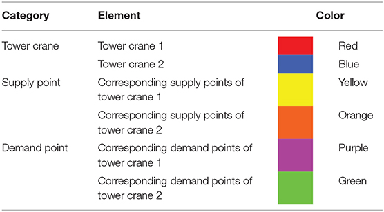
Table 1. Example for the normal-level scheme.
Fine-Level Scheme
The fine-level scheme displays the detailed information of lifting task scheduling, namely start and end, working status of tower crane, and workspace availability of supply and demand points of times in the pre-, no-load, loaded, and post-lifting processes for each lifting task. In the 4-D model, different times of tower cranes and corresponding supply and demand points are marked using a set of colors with specific hues and values so as to clarify key times of elements for each lifting task. An example for the fine-level scheme is shown in Table 2; times in the processes of tower crane 1 and corresponding supply and demand points are marked using red, yellow, and purple, respectively; and times in the processes of tower crane 2 and corresponding supply and demand points are marked using blue, orange, and green, respectively. For tower cranes, according to the working status, idle preparation times in the pre-lifting process, delay times in the no-load lifting process, delay times in the loaded lifting process, and transfer times in the post-lifting process are no colors; busy loading and unloading times in the loaded lifting process are light colors; busy motion times in the no-load lifting process are medium colors; and busy motion times in the loaded lifting process are dark colors. For supply points, according to the workspace availability, available motion and unloading times in the loaded lifting process and transfer times in the post-lifting process are no colors; unavailable delay and motion times in the no-load lifting process and delay and loading times in the loaded lifting process are light colors; and unavailable preparation times in the pre-lifting process are dark colors. For demand points, according to the workspace availability, available preparation times in the pre-lifting process, delay and motion times in the no-load lifting process and loading and motion times in the loaded lifting process are no colors; unavailable unloading times in the loaded lifting process are light colors; and unavailable transfer times in the post-lifting process are dark colors. Thus, key times of elements for each lifting task can be highlighted with the performance of lifting tasks by conducting 4-D simulation, and different stages can be defined according to the start and end of times in the processes of lifting tasks.
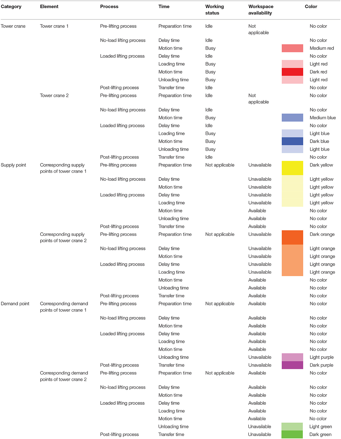
Table 2. Example for the fine-level scheme.
An Experimental Case Study
In this section, an example was used to demonstrate the proposed spatiotemporal modeling of lifting task scheduling for tower cranes. The example is in the seventh floor construction phase of a 36-story high-rise building project with two tower cranes, and it consists of 10 lifting tasks from the ground floor to the seventh floor, 16 lifting tasks from the third floor to the seventh floor, and two lifting tasks from the seventh floor to the ground floor. Two supply points S1 and S2 and one demand point D3 are on the ground floor; eight supply points S3, S4, S5, S6, S7, S8, S9, and S10 are on the third floor; two supply points S11 and S12 and two demand points D1 and D2 are on the seventh floor; there are three common supply and demand points, namely S1 and D3, S11 and D2, and S12 and D3; and the 3-D model for the example is shown in Figure 3. The lifting weight, supply and demand points, and available tower crane for each lifting task are listed in Table 3. The lifting weight ranges from 42.50 kg of lifting task 28 to 5788.71 kg of lifting tasks 9 and 10. Sixteen lifting tasks (i.e., lifting tasks 1 to 10, 21 to 24, and 27 to 28) are covered by tower cranes C1 and C2. Six lifting tasks (i.e., lifting tasks 15 to 18, 25 to 26) are covered by tower crane C1, and six lifting tasks (i.e., lifting tasks 11 to 14, and 19 to 20) are covered by tower crane C2. The coordinates of the tower cranes and supply and demand points are detailed in Table 4. The specifications of the two tower cranes are listed in Table 5, which consists of the jib length, maximum working radius, maximum lifting height, maximum lifting capacity, maximum hoist velocity of the hook, maximum radial velocity of the trolley, maximum slewing velocity of the jib, and height ranking. Tower crane C1 is 52.092 m, 50 m, 241.5 m, 8000 kg, 75 m/min, 100 m/min, 0.6 r/min, and shorter, respectively, and tower crane C2 is 52.63 m, 50 m, 275 m, 12,500 kg, 80 m/min, 100 m/min, 0.72 r/min, and taller, respectively.
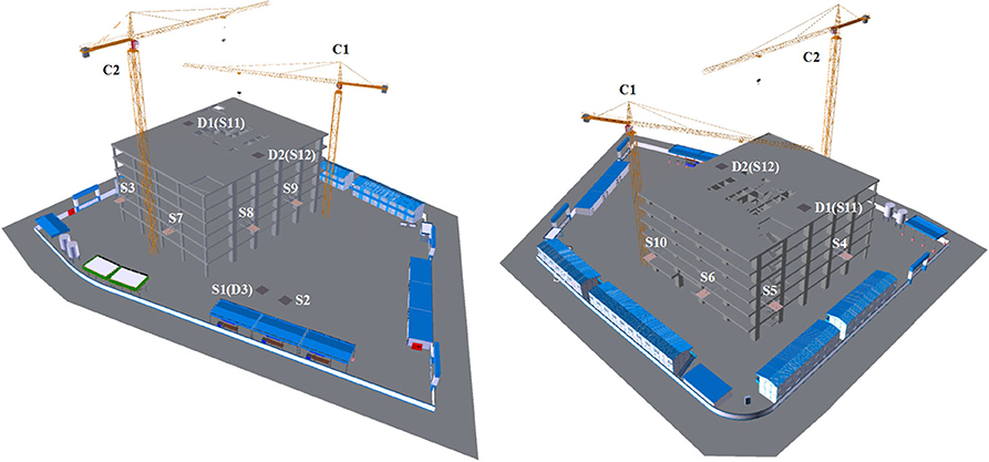
Figure 3. 3-D model for the example.
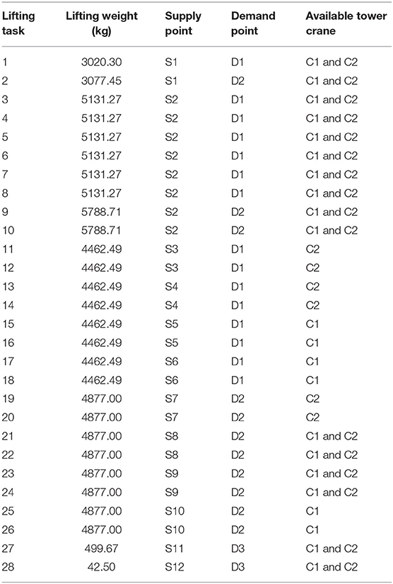
Table 3. Information of the lifting tasks.
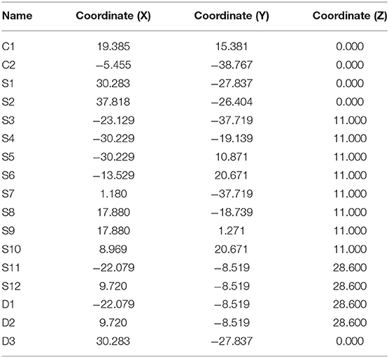
Table 4. Coordinates of the tower cranes and supply and demand points.
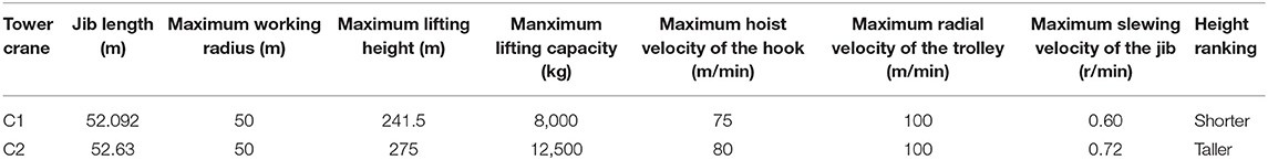
Table 5. Specifications of the tower cranes.
The collision criteria of overlapping tower cranes were set according to Wu et al. (2020). The tabu search parameters were set as follows: the neighboring solution size Sns was 100, the tabu list size Stl was 10, and the maximum iterations Imax were 100. In total, 10 searches with random feasible initial solutions were conducted, and the complete and close-up views of the convergence processes are illustrated in Figures 4A,B, respectively. The total times of the initial solutions range from 276.88 to 318.27 min. The total times of the optimized solutions range from 218.20 to 220.27 min. The reduction rates range from 20.91 to 31.22%, and the average total time is reduced by 25.82%.
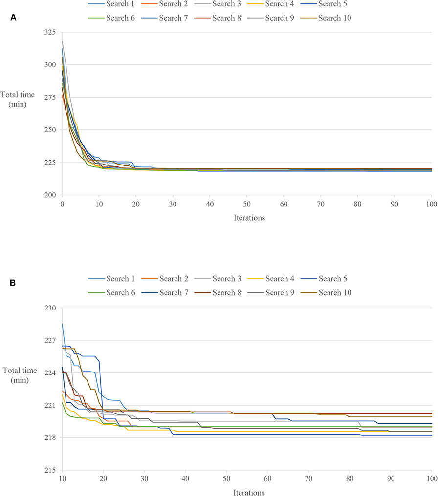
Figure 4. Complete (A) and close-up (B) views of the convergence processes for 10 searches.
The first three tasks of the scheduling with the minimum total time (i.e., Search 5) are detailed in Table 6. The first lifting task is lifting task 4 performed by tower crane C1 with the duration of 15.58 min from 0.00 to 15.58 min, and its durations for the pre-, no-load, loaded, and post-lifting processes are 7.70 min from 0.00 to 7.70 min, 0.00 min from 7.70 to 7.70 min, 2.75 min from 7.70 to 10.45 min, and 5.13 min from 10.45 to 15.58 min, respectively. The second lifting task is lifting task 11 performed by tower crane C2 with the duration of 13.55 min from 15.58 to 29.13 min, and its durations for the pre-, no-load, loaded, and post-lifting processes are 6.70 min from 15.58 to 22.28 min, 0.00 min from 22.28 to 22.28 min, 2.39 min from 22.28 to 24.67 min, and 4.46 min from 24.67 to 29.13 min, respectively. The third lifting task is lifting task 24 performed by tower crane C1 with the duration of 16.99 min from 15.58 to 32.57 min, and its durations for the pre-, no-load, loaded, and post-lifting processes are 7.32 min from 15.58 to 22.90 min, 2.54 min from 22.90 to 25.44 min, 2.25 min from 25.44 to 27.69 min, and 4.88 min from 27.69 to 32.57 min, respectively. These three lifting tasks are displayed with 4-D simulation by adopting the normal- and fine-level schemes as follows.
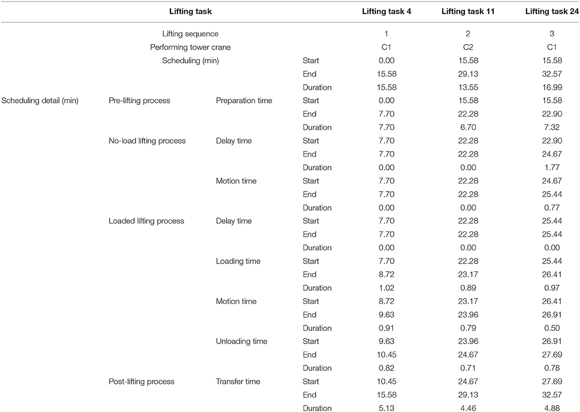
Table 6. Details of the first three tasks of Search 5.
Figure 5 shows 4-D simulation adopting the normal-level scheme. It has three stages according to the start and end of the lifting tasks as listed in Table 7. Tower crane C1 and its corresponding supply and demand points are marked using red, yellow, and purple, respectively. Tower crane C2 and its corresponding supply and demand points are marked using blue, orange, and green, respectively.
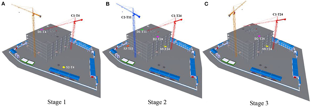
Figure 5. 4-D simulation adopting the normal-level scheme [(A), (B) and (C) are Stages 1, 2 and 3, respectively].
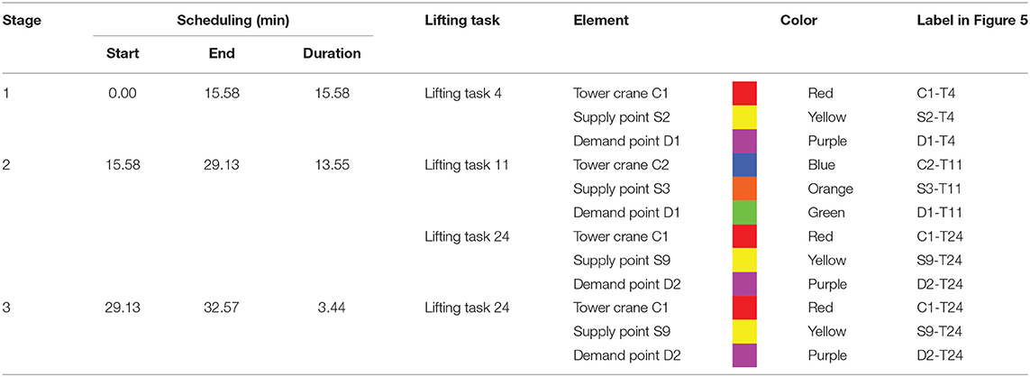
Table 7. Stage information adopting the normal-level scheme.
In stage 1, from 0.00 to 15.58 min, lifting task 4 from supply point S2 to demand point D1 is performed by tower crane C1. Tower crane C1 (labeled C1-T4), supply point S2 (labeled S2-T4), and demand point D1 (labeled D1-T4) are marked using red, yellow, and purple, respectively, as shown in Figure 5A.
In stage 2, from 15.58 to 29.13 min, lifting task 11 from supply point S3 to demand point D1 is performed by tower crane C2, and lifting task 24 from supply point S9 to demand point D2 is performed by tower crane C1. Tower crane C2 (labeled C2-T11), supply point S3 (labeled S3-T11), and demand point D1 (labeled D1-T11) are marked using blue, orange, and green, respectively, and tower crane C1 (labeled C1-T24), supply point S9 (labeled S9-T24), and demand point D2 (labeled D2-T24) are marked using red, yellow, and purple, respectively, as shown in Figure 5B.
In stage 3, from 29.13 to 32.57 min, lifting task 24 from supply point S9 to demand point D2 goes on being performed by tower crane C1. Tower crane C1 (labeled C1-T24), supply point S9 (labeled S9-T24), and demand point D2 (labeled D2-T24) are marked using red, yellow, and purple, respectively, as shown in Figure 5C.
Figure 6 shows 4-D simulation adopting the fine-level scheme. It has 16 stages according to the start and end of the times in the processes of the lifting tasks as listed in Table 8. For tower crane C1, the preparation time in the pre-lifting process, the delay time in the no-load lifting process, the delay time in the loaded lifting process, and the transfer time in the post-lifting process are no colors; the loading and unloading times in the loaded lifting process are light red; the motion time in the no-load lifting process is medium red; and the motion time in the loaded lifting process is dark red. For its corresponding supply points, the motion and unloading times in the loaded lifting process and the transfer time in the post-lifting process are no colors; the delay and motion times in the no-load lifting process and the delay and loading times in the loaded lifting process are light yellow; and the preparation time in the pre-lifting process is dark yellow. For its corresponding demand points, the preparation time in the pre-lifting process, the delay and motion times in the no-load lifting process and the delay, loading and motion times in the loaded lifting process are no colors; the unloading time in the loaded lifting process is light purple; and the transfer time in the post-lifting process is dark purple. For tower crane C2, the preparation time in the pre-lifting process, the delay time in the no-load lifting process, the delay time in the loaded lifting process and transfer time in the post-lifting process are no colors; the loading and unloading times in the loaded lifting process are light blue; the motion time in the no-load lifting process is medium blue; and the motion time in the loaded lifting process is dark blue. For its corresponding supply points, the motion and unloading times in the loaded lifting process and the transfer time in the post-lifting process are no colors; the delay and motion times in the no-load lifting process and the delay and loading times in the loaded lifting process are light orange; and the preparation time in the pre-lifting process is dark orange. For its corresponding demand points, the preparation time in the pre-lifting process, the delay and motion times in the no-load lifting process and the delay, loading and motion times in the loaded lifting process are no colors; the unloading time in the loaded lifting process is light green; and the transfer time in the post-lifting process is dark green.
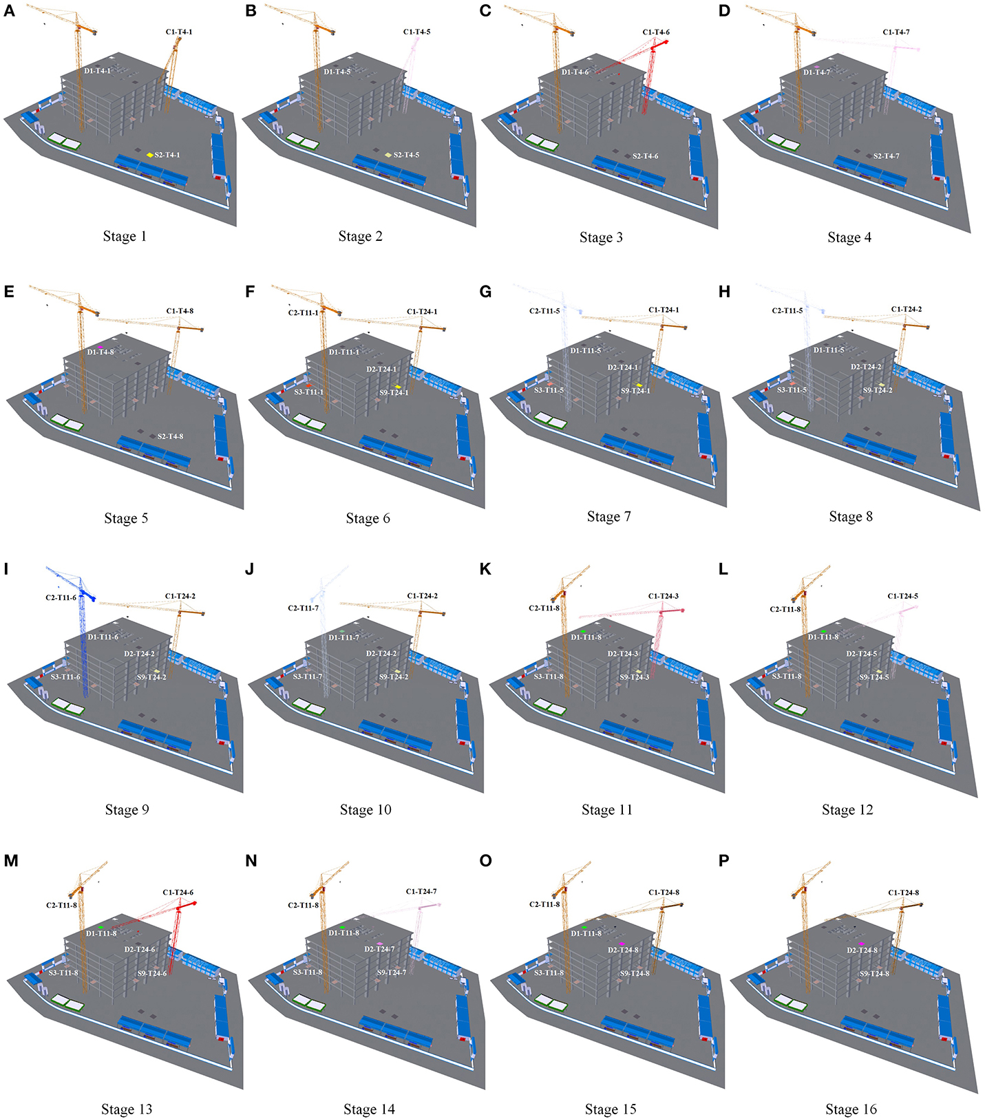
Figure 6. 4-D simulation adopting the fine-level scheme [(A–P) are Stages 1 to 16, respectively].
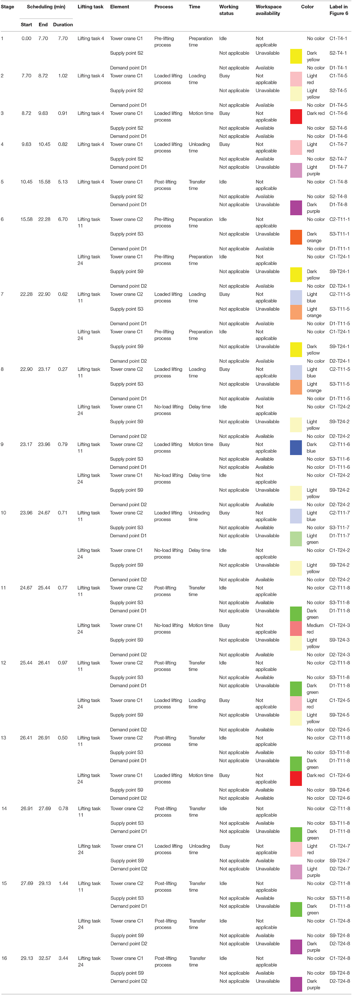
Table 8. Stage information adopting the fine-level scheme.
In stage 1, from 0.00 to 7.70 min, the material for lifting task 4 is prepared at supply point S2. Tower crane C1 (labeled C1-T4-1), supply point S2 (labeled S2-T4-1), and demand point D1 (labeled D1-T4-1) are idle, unavailable, and available, respectively, and they are marked using no color, dark yellow, and no color, respectively, as shown in Figure 6A.
In stage 2, from 7.70 to 8.72 min, the material for lifting task 4 is loaded to tower crane C1 at supply point S2. Tower crane C1 (labeled C1-T4-5), supply point S2 (labeled S2-T4-5), and demand point D1 (labeled D1-T4-5) are busy, unavailable, and available, respectively, and they are marked using light red, light yellow, and no color, respectively, as shown in Figure 6B.
In stage 3, from 8.72 to 9.63 min, the material for lifting task 4 is lifted by tower crane C1 from supply point S2 to demand point D1. Tower crane C1 (labeled C1-T4-6), supply point S2 (labeled S2-T4-6), and demand point D1 (labeled D1-T4-6) are busy, available, and available, respectively, and they are marked using dark red, no color, and no color, respectively, as shown in Figure 6C.
In stage 4, from 9.63 to 10.45 min, the material for lifting task 4 is unloaded from tower crane C1 at demand point D1. Tower crane C1 (labeled C1-T4-7), supply point S2 (labeled S2-T4-7), and demand point D1 (labeled D1-T4-7) are busy, available, and unavailable, respectively, and they are marked using light red, no color, and light purple, respectively, as shown in Figure 6D.
In stage 5, from 10.45 to 15.58 min, the material for lifting task 4 is transferred at demand point D1. Tower crane C1 (labeled C1-T4-8), supply point S2 (labeled S2-T4-8), and demand point D1 (labeled D1-T4-8) are idle, available, and unavailable, respectively, and they are marked using no color, no color, and dark purple, respectively, as shown in Figure 6E.
In stage 6, from 15.58 to 22.28 min, the material for lifting task 11 is prepared at supply point S3, and the material for lifting task 24 is prepared at supply point S9. Tower crane C2 (labeled C1-T11-1), supply point S3 (labeled S3-T11-1), and demand point D1 (labeled D1-T11-1) are idle, unavailable, and available, respectively, and they are marked using no color, dark orange, and no color, respectively; tower crane C1 (labeled C1-T24-1), supply point S9 (labeled S9-T24-1), and demand point D2 (labeled D2-T24-1) are idle, unavailable, and available, respectively, and they are marked using no color, dark yellow, and no color, respectively, as shown in Figure 6F.
In stage 7, from 22.28 to 22.90 min, the material for lifting task 11 is loaded to tower crane C2 at supply point S3, and the material for lifting task 24 goes on being prepared at supply point S9. Tower crane C2 (labeled C1-T11-5), supply point S3 (labeled S3-T11-5), and demand point D1 (labeled D1-T11-5) are busy, unavailable, and available, respectively, and they are marked using light blue, light orange, and no color, respectively; tower crane C1 (labeled C1-T24-1), supply point S9 (labeled S9-T24-1), and demand point D2 (labeled D2-T24-1) are idle, unavailable, and available, respectively, and they are marked using no color, dark yellow, and no color, respectively, as shown in Figure 6G.
In stage 8, from 22.90 to 23.17 min, the material for lifting task 11 goes on being loaded to tower crane C2 at supply point S3, and the no-load motion of tower crane C1 from the last demand point D1 to supply point S9 is delayed. Tower crane C2 (labeled C1-T11-5), supply point S3 (labeled S3-T11-5), and demand point D1 (labeled D1-T11-5) are busy, unavailable, and available, respectively, and they are marked using light blue, light orange, and no color, respectively; tower crane C1 (labeled C1-T24-2), supply point S9 (labeled S9-T24-2), and demand point D2 (labeled D2-T24-2) are idle, unavailable, and available, respectively, and they are marked using no color, light yellow, and no color, respectively, as shown in Figure 6H.
In stage 9, from 23.17 to 23.96 min, the material for lifting task 11 is lifted by tower crane C2 from supply point S3 to demand point D1, and the no-load motion of tower crane C1 from the last demand point D1 to supply point S9 goes on being delayed. Tower crane C2 (labeled C1-T11-6), supply point S3 (labeled S3-T11-6), and demand point D1 (labeled D1-T11-6) are busy, available, and available, respectively, and they are marked using dark blue, no color, and no color, respectively; tower crane C1 (labeled C1-T24-2), supply point S9 (labeled S9-T24-2), and demand point D2 (labeled D2-T24-2) are idle, unavailable, and available, respectively, and they are marked using no color, light yellow, and no color, respectively, as shown in Figure 6I.
In stage 10, from 23.96 to 24.67 min, the material for lifting task 11 is unloaded from tower crane C2 at demand point D1, and the no-load motion of tower crane C1 from the last demand point D1 to supply point S9 goes on being delayed. Tower crane C2 (labeled C1-T11-7), supply point S3 (labeled S3-T11-7), and demand point D1 (labeled D1-T11-7) are busy, available, and unavailable, respectively, and they are marked using light blue, no color, and light green, respectively; tower crane C1 (labeled C1-T24-2), supply point S9 (labeled S9-T24-2), and demand point D2 (labeled D2-T24-2) are idle, unavailable, and available, respectively, and they are marked using no color, light yellow, and no color, respectively, as shown in Figure 6J.
In stage 11, from 24.67 to 25.44 min, the material for lifting task 11 is transferred at demand point D1, and tower crane C1 moves from the last demand point D1 to supply point S9. Tower crane C2 (labeled C1-T11-8), supply point S3 (labeled S3-T11-8), and demand point D1 (labeled D1-T11-8) are idle, available, and unavailable, respectively, and they are marked using no color, no color, and dark green, respectively; tower crane C1 (labeled C1-T24-3), supply point S9 (labeled S9-T24-3), and demand point D2 (labeled D2-T24-3) are busy, unavailable, and available, respectively, and they are marked using medium red, light yellow, and no color, respectively, as shown in Figure 6K.
In stage 12, from 25.44 to 26.41 min, the material for lifting task 11 goes on being transferred at demand point D1, and the material for lifting task 24 is loaded to tower crane C1 at supply point S9. Tower crane C2 (labeled C1-T11-8), supply point S3 (labeled S3-T11-8), and demand point D1 (labeled D1-T11-8) are idle, available, and unavailable, respectively, and they are marked using no color, no color, and dark green, respectively; tower crane C1 (labeled C1-T24-5), supply point S9 (labeled S9-T24-5), and demand point D2 (labeled D2-T24-5) are busy, unavailable, and available, respectively, and they are marked using light red, light yellow, and no color, respectively, as shown in Figure 6L.
In stage 13, from 26.41 to 26.91 min, the material for lifting task 11 goes on being transferred at demand point D1, and the material for lifting task 24 is lifted by tower crane C1 from supply point S9 to demand point D2. Tower crane C2 (labeled C1-T11-8), supply point S3 (labeled S3-T11-8), and demand point D1 (labeled D1-T11-8) are idle, available, and unavailable, respectively, and they are marked using no color, no color, and dark green, respectively; tower crane C1 (labeled C1-T24-6), supply point S9 (labeled S9-T24-6), and demand point D2 (labeled D2-T24-6) are busy, available, and available, respectively, and they are marked using dark red, no color, and no color, respectively, as shown in Figure 6M.
In stage 14, from 26.91 to 27.69 min, the material for lifting task 11 goes on being transferred at demand point D1, and the material for lifting task 24 is unloaded from tower crane C1 at demand point D2. Tower crane C2 (labeled C1-T11-8), supply point S3 (labeled S3-T11-8), and demand point D1 (labeled D1-T11-8) are idle, available, and unavailable, respectively, and they are marked using no color, no color, and dark green, respectively; tower crane C1 (labeled C1-T24-7), supply point S9 (labeled S9-T24-7), and demand point D2 (labeled D2-T24-7) are busy, available, and unavailable, respectively, and they are marked using light red, no color, and light purple, respectively, as shown in Figure 6N.
In stage 15, from 27.69 to 29.13 min, the material for lifting task 11 goes on being transferred at demand point D1, and the material for lifting task 24 is transferred at demand point D2. Tower crane C2 (labeled C1-T11-8), supply point S3 (labeled S3-T11-8), and demand point D1 (labeled D1-T11-8) are idle, available, and unavailable, respectively, and they are marked using no color, no color, and dark green, respectively; tower crane C1 (labeled C1-T24-8), supply point S9 (labeled S9-T24-8), and demand point D2 (labeled D2-T24-8) are idle, available, and unavailable, respectively, and they are marked using no color, no color, and dark purple, respectively, as shown in Figure 6O.
In stage 16, from 29.13 to 32.57 min, the material for lifting task 24 goes on being transferred at demand point D2. Tower crane C1 (labeled C1-T24-8), supply point S9 (labeled S9-T24-8), and demand point D2 (labeled D2-T24-8) are idle, available, and unavailable, respectively, and they are marked using no color, no color, and dark purple, respectively, as shown in Figure 6P.
Discussion
The proposed spatiotemporal modeling of lifting task scheduling for tower cranes, consisting of the lifting task scheduling optimization model and display method, has been described. Its concept was demonstrated by an example with 28 lifting tasks and two tower cranes. The lifting task scheduling optimization model takes the preparation time sorting and stacking materials at the supply point and the transfer time assigning and removing materials at the demand point into account through integrating the pre- and post-lifting processes for lifting tasks in addition to the no-load and loaded lifting processes. It enhances the integrity of the lifting task time model and improves the effectiveness of lifting task scheduling. The consideration of workspace availability avoids potential workspace congestion at supply and demand points and ensures smooth flow of lifting tasks as well as related construction tasks. For example, the demand points of lifting tasks 4 and 11 are both D1; according to the optimized lifting task scheduling, the end time of lifting task 4 and the start time of lifting task 11 are both 15.58 min; thus, there is no workspace congestion at this point, and lifting tasks 11 and 4 can both be performed smoothly. The lifting task scheduling display method introduces the normal- and fine-level schemes through combining the hue and value of color with 4-D simulation, and newly integrated pre- and post-lifting processes in lifting task scheduling are included in the fine-level scheme. It enriches the display way of lifting task scheduling and provides flexible schemes to meet the needs of different project teams. The marking method based on color hues and values can effectively clarify element information of lifting tasks and relationships among lifting tasks. For example, the tower crane and supply and demand points for a lifting task in each stage are highlighted in the normal-level scheme shown in Figure 5, and the working status of the tower crane and the workspace availability of the supply and demand points for a lifting task in each stage are highlighted in the fine-level scheme shown in Figure 6; thus, the performance of lifting tasks can be understood, and potential lifting problems can be found more easily by the project team.
The spatiotemporal modeling of lifting task scheduling for tower cranes currently focuses on a lifting task performed by a single tower crane, which is the most common case in construction projects. But, in some cases, there exists a lifting task that is handled by multiple tower cranes, especially in large-scale construction projects, which is not applicable using the proposed modeling. For this type of lifting task, the lifting task time model needs to redefine processes, add multiple lifting times, and consider the impact on other lifting tasks; meanwhile, the alternative solution structure used for optimization needs to be designed accordingly. In addition, an adaptive display method with 4-D simulation is also needed. These will be further studied in future work.
Conclusion
Lifting task scheduling for tower cranes plays an important role in the operation of construction projects. To improve the effectiveness of lifting task scheduling, the spatiotemporal modeling of lifting task scheduling for tower cranes is proposed in this study. On the one hand, in order to find the optimal lifting task scheduling in terms of minimum total time, a lifting task scheduling optimization model with a tabu search is created, and the alternative solution structures in the cases of single and multiple tower crane(s) are designed. Taking into account workspace availability at supply and demand points, in addition to the no-load and loaded lifting processes, the pre- and post- lifting processes that are primarily caused by material preparation and transfer times are integrated into the lifting task time model. On the other hand, in order to display element information of lifting tasks and complex relationships among lifting tasks intuitively and effectively, a lifting task scheduling display method with normal- and fine-level schemes is introduced through combining the hue and value of color with 4-D simulation. To verify the functionalities of the proposed spatiotemporal modeling, an example with 28 lifting tasks and two tower cranes was tested by 10 searches. The average total time of the optimized lifting task scheduling was reduced by 25.82%. The results of the optimized lifting task scheduling with the minimum total time were developed into the 4-D models using the normal- and fine-level schemes, and the lifting task scheduling was clearly displayed with 4-D simulation. This study contributes insights into lifting task scheduling from the perspective of spatiotemporal modeling, and effectively improves the quality of lifting task scheduling for tower cranes. This study focuses on the spatiotemporal modeling in the case of a lifting task that is performed by a single tower crane, and the case of a lifting task that is handled by multiple tower cranes will be involved in future work.
Data Availability Statement
The datasets generated for this study are available on request to the corresponding author.
Author Contributions
All authors listed have made a substantial, direct and intellectual contribution to the work, and approved it for publication.
Conflict of Interest
The authors declare that the research was conducted in the absence of any commercial or financial relationships that could be construed as a potential conflict of interest.
References
Abdelaziz, F. B., and Mir, H. (2016). An optimization model tabu search heuristic for scheduling of tasks on a radar sensor. IEEE Sens. J. 16, 6694–6702. doi: 10.1109/JSEN.2016.2587730
Abdel-Khalel, H., Shawki, K., and Adel, M. (2013). A computer-based model for optimizing the location of single tower crane in construction sites. Int. J. Eng. Sci. Technol. 2, 438–446. Available online at: http://www.ijesit.com/Volume%202/Issue%202/IJESIT201302_68.pdf (accessed June 13, 2020).
Abdelmegid, M. A., Shawki, K. M., and Abdel-Khalek, H. (2015). Ga optimization model for solving tower crane location problem in construction sites. Alex. Eng. J. 54, 519–526. doi: 10.1016/j.aej.2015.05.011
Al Hattab, M., Zankoul, E., Barakat, M., and Hamzeh, F. (2018). Crane overlap operational flexibility: balancing utilization, duration, safety. Constr. Innov. 18, 43–63. doi: 10.1108/CI-11-2016-0062
Al Hattab, M., Zankoul, E., and Hamzeh, F. R. (2017). Near-real-time optimization of overlapping tower crane operations: a model case study. J. Comp. Civil Eng. 31:05017001. doi: 10.1061/(ASCE)CP.1943-5487.0000666
Al-Hussein, M., Niaz, M. A., Yu, H., and Kim, H. (2006). Integrating 3D visualization simulation for tower crane operations on construction sites. Automat. Constr. 15, 554–562. doi: 10.1016/j.autcon.2005.07.007
Edwards, G., Sørensen, C. G., Bochtis, D. D., and Munkholm, L. J. (2015). Optimised schedules for sequential agricultural operations using a tabu search method. Comput. Electron. Agric. 117, 102–113. doi: 10.1016/j.compag.2015.07.007
Einakian, S., and Newman, T. S. (2019). An examination of color theories in map-based information visualization. J. Comp. Lang. 51, 143–153. doi: 10.1016/j.cola.2018.12.003
Emery, K. J., Volbrecht, V. J., Peterzell, D. H., and Webster, M. A. (2017). Variations in normal color vision. vi. factors underlying individual differences in hue scaling their implications for models of color appearance. Vision Res. 141, 51–65. doi: 10.1016/j.visres.2016.12.006
García de Soto, B., Rosarius, A., Rieger, J., Chen, Q., and Adey, B. T. (2017). Using a tabu-search algorithm 4D models to improve construction project schedules. Procedia Eng. 196, 698–705. doi: 10.1016/j.proeng.2017.07.236
Glover, F. (1986). Future paths for integer programming links to artificial intelligence. Comp. Operat. Res. 13, 533–549. doi: 10.1016/0305-0548(86)90048-1
Huang, C., and Wong, C. K. (2018). Optimization of crane setup location servicing schedule for urgent material requests with non-homogeneous non-fixed material supply. Autom. Constr. 89, 183–198. doi: 10.1016/j.autcon.2018.01.015
Huang, C., Wong, C. K., and Tam, C. M. (2011). Optimization of tower crane material supply locations in a high-rise building site by mixed-integer linear programming. Autom. Constr. 20, 571–580. doi: 10.1016/j.autcon.2010.11.023
Irizarry, J., and Karan, E. P. (2012). Optimizing location of tower cranes on construction sites through gis bim integration. J. Info. Technol. Constr. 17, 351–366. Available online at: http://www.itcon.org/2012/23
Ji, Y., and Leite, F. (2018). Automated tower crane planning: leveraging 4-dimensional bim rule-based checking. Autom. Constr. 93, 78–90. doi: 10.1016/j.autcon.2018.05.003
Logvinenko, A. D., Funt, B., and Godau, C. (2015). How metamer mismatching decreases as the number of colour mechanisms increases with implications for colour lightness constancy. Vision Res. 113, 65–70. doi: 10.1016/j.visres.2015.05.009
Marzouk, M., and Abubakr, A. (2016). Decision support for tower crane selection with building information models genetic algorithms. Autom. Constr. 61, 1–15. doi: 10.1016/j.autcon.2015.09.008
Monghasemi, S., Nikoo, M. R., and Adamowski, J. (2016). Sequential ordering of crane service requests considering the pending times of the requests: an approach based on game theory optimization techniques. Autom. Constr. 70, 62–76. doi: 10.1016/j.autcon.2016.06.006
Rodriguez-Ramos, W. E., and Francis, R. L. (1983). Single crane location optimization. J. Constr. Eng. Manag. 109, 387–397. doi: 10.1061/(ASCE)0733-9364(1983)109:4(387)
Samavati, M., Essam, D., Nehring, M., and Sarker, R. (2017). A local branching heuristic for the open pit mine production scheduling problem. Eur. J. Oper. Res. 257, 261–271. doi: 10.1016/j.ejor.2016.07.004
Shapira, A., Lucko, G., and Schexnayder, C. J. (2007). Cranes for building construction projects. J. Constr. Eng. Manag. 133, 690–700. doi: 10.1061/(ASCE)0733-9364(2007)133:9(690)
Stuart, G. W., Barsdell, W. N., and Day, R. H. (2014). The role of lightness, hue saturation in feature-based visual attention. Vision Res. 96, 25–32. doi: 10.1016/j.visres.2013.12.013
Sugimoto, Y., Seki, H., Samo, T., and Nakamitsu, N. (2016). 4D cad-based evaluation system for crane deployment plans in construction of nuclear power plants. Automa. Constr. 71, 87–98. doi: 10.1016/j.autcon.2016.04.004
Wang, J., Zhang, X., Shou, W., Wang, X., Xu, B., Kim, M. J., et al. (2015). A bim-based approach for automated tower crane layout planning. Automa. Constr. 59, 168–178. doi: 10.1016/j.autcon.2015.05.006
Wu, K., García de Soto, B., and Zhang, F. (2020). Spatio-temporal planning for tower cranes in construction projects with simulated annealing. Automa. Constr. 111:103060. doi: 10.1016/j.autcon.2019.103060
Younes, A., and Marzouk, M. (2018). Tower cranes layout planning using agent-based simulation considering activity conflicts. Automa. Constr. 93, 348–360. doi: 10.1016/j.autcon.2018.05.030
Zavichi, A., and Behzadan, A. H. (2011). “A real time decision support system for enhanced crane operations in construction manufacturing,” in 2011 Asce International Workshop On Computing In Civil Engineering (Miami: American Society of Civil Engineers), 586–593. doi: 10.1061/41182(416)72
Zavichi, A., Madani, K., Xanthopoulos, P., and Oloufa, A. A. (2014). Enhanced crane operations in construction using service request optimization. Automa. Constr. 47, 69–77. doi: 10.1016/j.autcon.2014.07.011
Zhang, P., Harris, F. C., and Olomolaiye, P. O. (1996). A computer-based model for optimizing the location of a single tower crane. Build. Res. Inf. 24, 113–123. doi: 10.1080/09613219608727511
Keywords: spatiotemporal modeling, construction project management, tower crane, lifting task scheduling, optimization, tabu search, building information modeling (BIM), 4-D simulation
Citation: Wu K and García de Soto B (2020) Spatiotemporal Modeling of Lifting Task Scheduling for Tower Cranes With a Tabu Search and 4-D Simulation. Front. Built Environ. 6:79. doi: 10.3389/fbuil.2020.00079
Received: 28 November 2019; Accepted: 04 May 2020;
Published: 16 July 2020.
Edited by:
Hongling Guo, Tsinghua University, ChinaReviewed by:
Serdar Durdyev, Ara Institute of Canterbury, New ZealandChunlin Wu, Beihang University, China
Copyright © 2020 Wu and García de Soto. This is an open-access article distributed under the terms of the Creative Commons Attribution License (CC BY). The use, distribution or reproduction in other forums is permitted, provided the original author(s) and the copyright owner(s) are credited and that the original publication in this journal is cited, in accordance with accepted academic practice. No use, distribution or reproduction is permitted which does not comply with these terms.
*Correspondence: Borja García de Soto, garcia.de.soto@nyu.edu