 Wei Chun Tai
 Masahiro Ikenaga
- Department of Architecture, Faculty of Environmental and Urban Engineering, Graduate School of Science and Engineering, Kansai University, Suita, Japan
Connecting two buildings has been proved as an effective method of structural control for alleviating seismic responses. Researchers have proposed that two adjacent buildings through supplemental energy dissipating devices to mitigate the buildings’ responses. Numerous researchers have proposed various methods: active, passive, and semi-active control strategies. In Japan, some applications of coupled buildings control have been successfully implemented by utilizing passive and active control technology. Magnetorheological (MR) dampers have been identified as semi-active devices that can be used to reduce the vibration of the seismic structures during various types of ground motions. They can offer the adaptability of active devices, stability, and reliability of passive devices. Nevertheless, one of the difficulties in application of the MR dampers is the development of the appropriate control algorithms. Accordingly, this study presents the implementation of the adaptive neuro-fuzzy inference system (ANFIS) controller for earthquake hazard mitigation under coupled buildings control system with base-isolated building connecting to the free wall by MR dampers. The ANFIS whose training data is based on the Linear Quadratic Regulator (LQR) method is conducted to modify the parameters of the fuzzy logic controller and optimize the fuzzy rules. The performance of MR dampers is evaluated under seismic response. It is compared under four methods, including passive-off, passive-on, and two semi-active control strategies: ANFIS and LQR. Besides, various types of feedback of the ANFIS operated as two-input single output feedback system are investigated to assess the performance of the developed control scheme for structural vibration control. The numerical simulation results show that the proposed semi-active control system consisting of coupled buildings system and MR dampers by utilizing ANFIS can be effective in mitigating seismic responses of structures.
Introduction
In recent years, designing seismic buildings to withstand a broad range of earthquakes has become desirable to increase earthquake resilience. Many studies focused on developing of various practical structural control strategies to strengthen the seismic buildings. Structural control can be divided into four categories: passive, active, semi-active, and hybrid control systems by installing control devices to the structure. A semi-active control system has recently generated significant interest from researchers due to the combination of passive and active control systems characteristics. Researchers have proposed various schematic concepts for installing control devices. Connecting two buildings through control devices, called coupled buildings control, has also been explored. The structures are connected by fluid viscous-elastic dampers (Zhang and Xu, 1999, 2000; Yang et al., 2003) and friction dampers (Bhaskararao and Jangid, 2006; Ng and Xu, 2006) to improve the performance of the couple buildings. In Japan, a hybrid passive control system connecting a base-isolated building to a non-base isolated building (free wall) was first proposed by Obayashi Corporation and has been deeply investigated (Murase et al., 2013; Taniguchi et al., 2016; Hayashi et al., 2018; Nakamura et al., 2021). It is demonstrated that a hybrid passive control system is effective for long-period and pulse-like ground motions and has high redundancy and resilience against many disturbances.
Active control devices implemented a more advanced strategy to connect multiple high-rise buildings (Seto and Matsumoto, 1999). In numerous studies, semi-active control devices have also been utilized as connecting dampers (Yan and Zhou, 2006; Bharti et al., 2010; Uz and Hadi, 2014; Kim, 2016). In the past, magnetorheological (MR) dampers employing MR fluids to provide control capability have been identified as potential devices for semi-active control of seismic buildings due to their large force capacity, high dynamic range with the low power requirement.
Few investigations have been conducted about the effect of the distribution of dampers between coupled buildings. Bhaskararao and Jangid (2006) analyzed the optimal force of the friction dampers for decreasing the seismic response of coupled buildings system. In addition, they confirmed that it is not necessary to utilize connecting dampers on all floors, but a small number of dampers connected in proper locations can significantly reduce the seismic responses of the coupled buildings system. On the other hand, Bharti et al. (2010) proposed coupled buildings connected with MR dampers. Both studies suggested that providing linkages at all floor levels is unnecessary. Nevertheless, no optimal distribution solution was delivered.
Bigdeli et al. (2012) presented optimization algorithms for locating a limited number of viscous dampers to reduce seismic response of coupled buildings during different earthquakes. Uz and Hadi (2014) also proposed a multi-objective optimization approach to obtain an optimal design method for minimizing the number of MR dampers between the coupled buildings.
The semi-active control algorithms for MR dampers can be classified into two categories. The first category is based on a mathematical model to operate. These methods contain Linear Quadratic Regulator (LQR), Linear Quadratic Gaussian (LQG), H2/LQG strategies, and Lyapunov’s direct approach control methods (Dyke, 1996; Dyke et al., 1996; Chang and Zhou, 2002; Xu and Zhang, 2002; Bharti et al., 2010). The second category is known as non-model-based control method. It relies on the system’s measured responses and the accurate mathematical model is not necessary. This category includes neural network and fuzzy logic control (FLC) method (Yan and Zhou, 2006; Gu and Oyadiji, 2008; Uz and Hadi, 2014; Al-Fahdawi et al., 2019).
Researchers have interested in fuzzy logic control theory over the past years. Because the fuzzy sets and rules require a comprehensive understanding of the system dynamics, it is necessary to pre-determine the system properly.
One of the main disadvantages of fuzzy controllers is their inability of learn. As a result, the use of knowledge and experience of controller database specialists is essential. To overcome this problem, a learning process can be applied and modify the fuzzy logic controller. Several methods based on learning-capable fuzzy controllers have been proposed. The genetic algorithm (GA) inspired by evolutionary theory is one of the effective methods for designing fuzzy controllers to develop an appropriate fuzzy controller. (Yan and Zhou, 2006; Uz and Hadi, 2014). GA can be applied as a multi-objective optimization tool to reduce both the displacement response and acceleration response in structural vibration control applications.
Another method is the combination of neural networks and fuzzy logic in neuro-fuzzy controllers. The neural-fuzzy controller combines neural networks and a fuzzy inference system that compensates for the fuzzy control deficiencies through neural network training and adaptability.
In the previous research, Gu et al. (2017, 2019) have successfully used the neuro network control algorithm to operate the MR elastomer isolator. It can be identified that the semi-active control system in which the MR-based devices in combination with the neuro network system or the neuro-fuzzy logic controller can effectively reduce the responses of the structure.
On the other hand, the adaptive neuro-fuzzy inference system (ANFIS) is one of the most important and widely used types of neuro-fuzzy networks (Jang, 1993). In the previous studies, the ANFIS has been proved as an effective method to modify the fuzzy membership function and to create the fuzzy rules (Gu and Oyadiji, 2008; César and Barros, 2016; Al-Fahdawi et al., 2019).
Al-Fahdawi et al. (2019) investigated the effectiveness of the ANFIS controller which is operated as a single-input single-output feedback system under three schemes. It can be identified that the MR dampers operated by the ANFIS controller can effectively reduce the responses of two connecting buildings. César and Barros (2016) demonstrated the semi-active control system in which the ANFIS controller is implemented to optimize the fuzzy inference rule as two-input single-output feedback system. It reveals that the ANFIS with two-input single-output feedback system can alleviate the responses of the seismic building.
In this study, the ANFIS controller implemented as two-input single-output feedback system is used to establish parameters for fuzzy membership functions and creates fuzzy rules. Moreover, the four types of the feedback in the semi-active control system are chosen to compare the numerical results under the ground motions. In order to assess the effectiveness of the proposed semi-active control system, three types of strategies: passive-off, passive-on and semi-active control algorithms (four schemes of ANFIS and LQR) are investigated under the different ground motions. The numerical results of the three control strategies are examined and in comparison with the uncontrolled (unconnected) strategy.
Multiple degrees of freedom model of base-isolated and building connection
Murase et al. (2013) proposed a hybrid passive control system with a base-isolated building connecting to a non-base isolated building by oil dampers. In this study, MR dampers are utilized as connecting dampers instead of oil dampers. The system is modeled using the MDOF mass-spring-dashpot model as depicted in Figure 1.
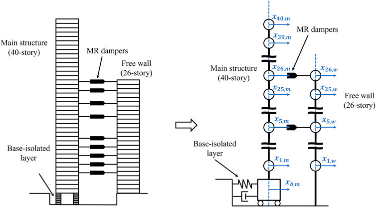
FIGURE 1. The model of the coupled buildings system with base isolation and building connecting.
The base-isolated layer consists of a natural rubber isolator and oil dampers. The floor mass of the main structure, the free wall, and the base isolation floor is 170 t, 100 t, and 510 t, respectively. The story height of each building is 3.5 m across all stories.
The fundamental natural period of main structure is 6.73 s, while those of the superstructure of the base-isolated building and the free wall are 3.01 and 2.13 s. The stiffness distribution of each building is trapezoidal (the top-to-bottom story stiffness ratio is 1/3). The damping ratio of the base-isolated layer for a rigid super-structure is 0.15, and the structural damping ratio of the super-structure is set to 0.02 (stiffness-proportional damping), and the damping ratio of the free wall is 0.03 (stiffness-proportional damping).
Model of magneto-rheological (MR) damper
Spencer et al. (1997) proposed “a phenomenological model to characterize the behavior of an MR damper prototype”. Figure 2 illustrates a simple mechanical idealization of an MR damper based on a Bouc-Wen hysteresis model, which was developed and shown to accurately predict the behavior of an MR damper over a broad range of inputs. It is governed by the following simultaneous equations.
where z is the evolution variable, which is the scale factor of Bouc-Wen hysteresis, α, γ, β, n, and A are the correlation coefficients of the hysteresis parameter that control the shape of the hysteresis loop.
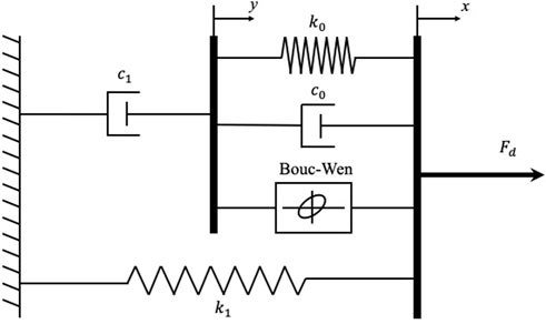
FIGURE 2. Modified Bouc-Wen model for MR damper, (Spencer et al., 1997).
y is internal displacement, c1 is viscous damping coefficient at low velocity, c0 is viscous damping observed at large velocities, k1 is stiffness of the accumulator, and k0 is spring stiffness coefficient at high velocity. Furthermore, x is the relative displacement of the spring, x0 is the initial relative displacement, and k1, k0, γ, β, n, and A are constant.
The parameters dependent on the applied voltage are expressed as follows:
The dynamics involved in reaching rheological equilibrium in the MR damper are accounted for through the first-order filter.
v is the voltage applied to the current generator.
In this study, damper parameters are chosen to have a capacity of 600 kN at a maximum voltage of Vmax = 3 Volts. The mechanical properties of the MR damper are listed in Table 1 (Bharti et al., 2010).
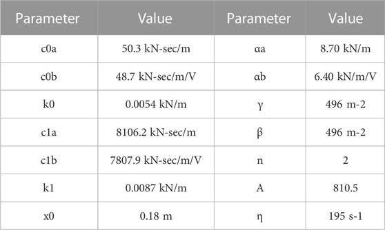
TABLE 1. Parameters of MR damper.
The equation of motion
The governing equations of the motion are presented in matrix form below.
where
Furthermore,
where O1 (41×26) and O2 (26×41) are null matrices, Mm and Mw are the mass matrices of the main structure, and the free wall which can be described as follows.
Km and Kw are stiffness matrices of the main structure and the free wall, respectively.
The governing equation of motion is:
where y is the state variable, A is the system matrix composed of structural mass, stiffness and damping matrices, Bd is the distribution matrix of the damper, and E is the matrix of excitation force. The matrices are expressed as follows:
where I and O are the identity and null matrices, respectively.
In this study, the effect of the bending is neglected and the coupled buildings control system does not overturn during the ground motions.
Evaluation criteria
Different sets of evaluation criteria are utilized to evaluate the buildings’ performance in the structural control benchmark problem (Ohtori et al., 2004). The evaluation criterion minimizes the non-dimensionalized peak response due to the earthquake records, in which the smaller values of the evaluation criteria indicate superior performance. The set of evaluation criteria applied in this study to compare the performance of the structural control is a different method based on the building peak responses, as shown in the following equations:
with the range i = [1 40], i = [1 26] (only above the ground level) for the main structure and free wall, respectively.
Where
The locations of connecting dampers
Fukumoto and Takewaki, (2017) proposed five cases of the location of the connecting dampers in the adjacent coupled buildings. In this study, modal analysis determines the locations of connecting dampers. The model analyses of the main structure and free wall are displayed in Figure 3. The dampers are installed on the 5th, 7th, 9th, 11th, 13th, 18th, 21st, 24th, and 26th floors.
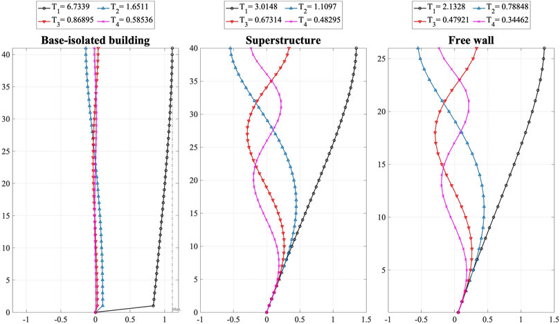
FIGURE 3. Modal analyses of each building.
Adaptive neuro-fuzzy inference system (ANFIS)
In this study, the Adaptive Neuro-Fuzzy Inference system (ANFIS) is utilized to improve the learning ability of the fuzzy logic controller. It makes the system less dependent on expert knowledge. ANFIS is composed of five layers and the schematic of ANFIS architecture is shown in Figure 4. It uses the Takagi and Sugeno’s fuzzy if-then rules as follows:
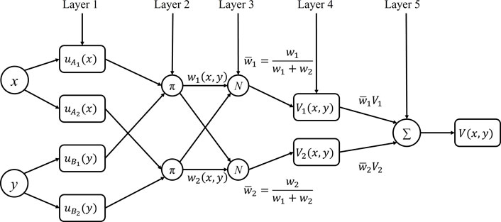
FIGURE 4. The architecture of ANFIS.
Rule 1: If x is A1, y is B1, then
Rule 2: If x is A2, y is B2, then
Rule N: If x is An, y is Bn, then
where x and y are model inputs and
The node functions in the same layer are of the same function family as explained below: (
Layer 1: Every node i in this layer is a square node with a node function
where
Layer 2: Every node i in this layer is labeled π in which wi are calculated by multiplying the membership values as follows.
Layer 3: The nodes in this layer is circle nodes labeled N. The normalized firing strength is calculated in this layer. It is the ratio of the firing strength of the ith rule to the total sum of all firing strengths:
Layer 4: Every node i in this layer is a square node with a node function
where
Layer 5: The single node in this layer is a circle node labeled ∑, which computes the overall output as the summation of all incoming signals.
In this study, the training data of ANFIS is produced using Linear Quadratic Regulator (LQR) assuming full-state feedback. The LQR control scheme is established on the principle of minimize the cost function J as the following equation:
Where Q ∈
The optimal damping force can be written as below:
where P is the solution of the Riccati matrix differential equation as below:
In this study, the parameters of the LQR are chosen as suggested by (Chang and Zhou, 2002).
where K and M are the stiffness and mass matrices of the coupled system.
An external disturbance defines the range and type of actual excitations, which the fuzzy controller is employed to handle. The training data should be representative of different situations under different excitations during the operation of the controller. As a result, the disturbance used by the controller is an artificial wave (Building Center of Japan, BCJ-L2).
In this study, there are four schemes of feedback. The comparative performance of four schemes of coupled buildings control is DV, VA, DD, and AA, as shown in the following.
DV is the displacement and velocity of the top floor in the main structure.
VA is the velocity and acceleration of the top floor in the main structure.
DD is the displacement of the top floor in the main structure and free wall, respectively.
AA is the acceleration of the top floor in the main structure and free wall, respectively.
The primary fuzzy logic controller develops in the current study with two inputs, and the damping force represents the fuzzy outcome. The membership functions of the Adaptive Neuro-Fuzzy Inference system are illustrated in Figure 5. In this study, seven Triangular membership functions are selected. These straight-line membership functions have the advantage of simplicity. In addition, triangular shapes are simple to implement and fast for computation. A trial and error method is used to determine the optimal membership functions for the model. The fuzzy sets for the input variables are denoted as follows: NL = negative large, NM = negative medium, and NS = negative small, ZR = zero, PL = positive large, PM = positive medium, PS = positive small.
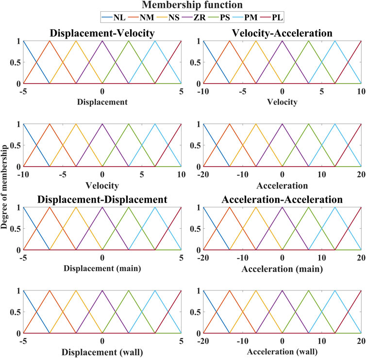
FIGURE 5. Member functions of the fuzzy logic controller in each case.
Data normalization
Before the training, input data should be normalized to increase networks’ efficiency in recognizing of the input and output data. It is helpful to increase the accuracy of prediction and scale the data to minimize the biasing of the networks by utilizing the normalization. Additionally, data normalization can also decrease the time of training. In this study, the Min-Max normalization method is used. When the Min-Max normalization is applied, each feature will lie within the new range of values and remain the same (Jayalakshmi and Santhakumaran, 2011). Moreover, this normalization method can preserve all the relationship in the data. The rescaling is often accomplished using a linear interpretation formula such as below:
where
In this study, the discourse domain range will vary depending on the input types. The displacement is rescaling between −5 and 5, the velocity is rescaling between −10 and 10, and the acceleration is rescaling between −20 and 20. If the range of the domain of discourse cannot accommodate all values of the input, the error will emerge.
Control algorithm
Dyke (1996) proposed a clipped-optimal control strategy, also known as clipped voltage law (CVL), for controlling an MR damper using acceleration feedback. The force generated in the MR damper cannot be directly commanded. Only the control voltage v applied to the current driver can be directly controlled. The algorithm for selecting the command signal for the MR damper can be stated as the following equations.
Figures 6, 7 depict the resultant fuzzy surface for the MR dampers on each floor under DV and DD strategies.
where

FIGURE 6. The fuzzy surface under DV strategy.
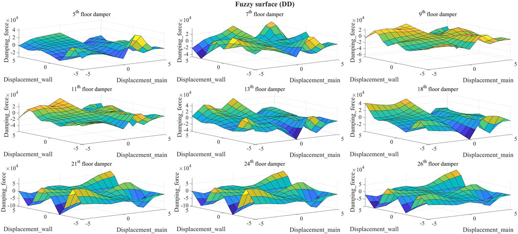
FIGURE 7. The fuzzy surface under DD strategy.
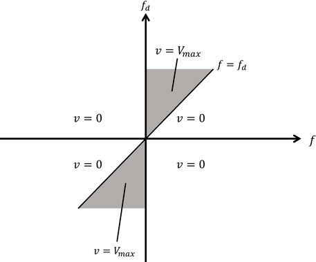
FIGURE 8. Graphical representation of algorithm (Dyke et al., 1996).
The voltage applied to MR damper should remain constant, when the MR damper provides the desired optimal force (i.e.,
Semi-active control system
In this study, a semi-active control system comprises two controllers (a system and a damper controller), as shown in Figure 9. The system controller calculates the desired damping force, and the damper controller serves on the voltage to be applied to the current driver to track the desired damping force.
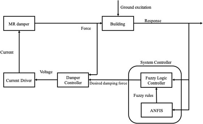
FIGURE 9. Block diagram of the semi-active system.
Numerical results and discussion
In this study, the Simulink blocks in MATLAB are utilized to build the Modified Bouc-Wen model of the MR dampers and the semi-active control system. Based on the fourth-order Runge-Kutta method, a MATLAB program is developed to solve the equations of motion for the couple buildings control system subjected to the excitations of the ground motions and the numerical results are presented in this section.
Time-history response
In this study, the effectiveness of proposed control strategies on MR damper is shown by seven control strategies comparison, those are Passive-off, Passive-on, semi-active (LQR-CVL), semi-active (FLC-CVL DD), semi-active (FLC-CVL DV), semi-active (FLC-CVL AA), and semi-active (FLC-CVL VA) control. MR dampers function as passive devices with the command voltage set to zero and maximum (Vmax = 3 Volts) under the Passive-off and Passive-on strategies. In contrast, semi-active control strategies utilize clipped-optimal control to determine the command voltage.
From the numerical results, the displacement of the base-isolated layer is less than 0.5 m, which complies with the building standard law in Japan.
Figure 10 depicts the time-history responses of top floor displacement and acceleration of the main structure for both the control and uncontrolled strategies under different earthquakes. In order to compare the performance of each case, the maximum response analysis is used in this study. Figures 11, 12 illustrate the profiles of the peak response of each building for both the control and uncontrolled strategies to different earthquakes. There is a significant reduction in displacement under the control strategies, except that under the Kobe earthquake (pulse-like ground motion), only semi-active (FLC-CVL DV) reduces the displacement of the top floor in the main structure. Figure 11 reveals that the acceleration of the main structure increases under the control strategies. Additionally, the increase of acceleration response by semi-active (FLC-CVL DV) is smaller than other control strategies. Both the peak displacement and acceleration of the free wall have a significant decrease under the control strategies.
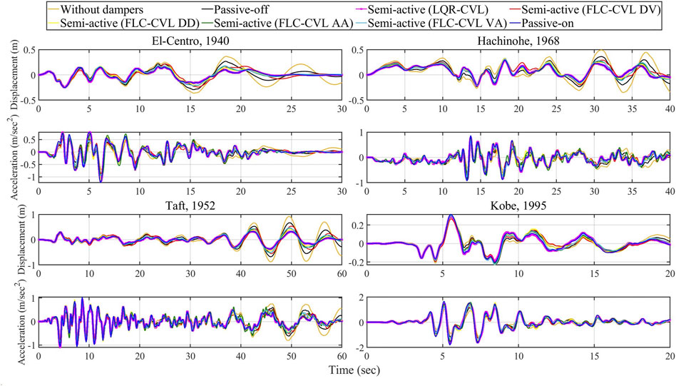
FIGURE 10. Time-history response of the top floor of the main structure.
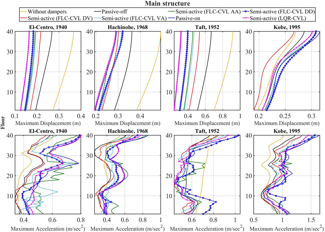
FIGURE 11. Maximum responses profiles of the main structure.
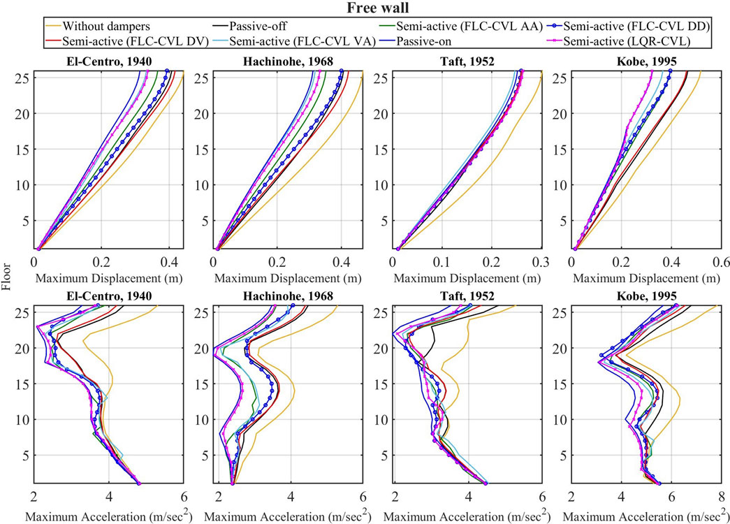
FIGURE 12. Maximum responses profiles of free wall.
Hysteresis behavior
Figure 13 illustrates the hysteresis behavior of MR dampers installed on the 5th, 13th, and 26th floors of coupled buildings, by four control strategies: Passive-on, Semi-active (FLC-CVL DV), Semi-active (FLC-CVL DD), Semi-active (LQR-CVL) under various earthquakes.
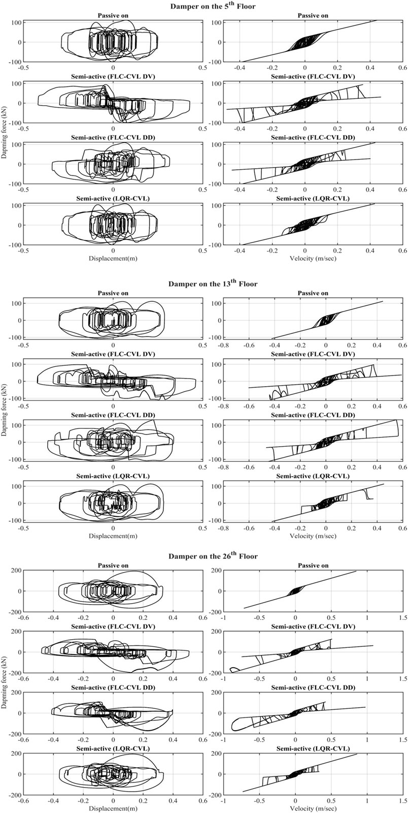
FIGURE 13. Hysteresis behavior of MR dampers under Taft (PGV = 0.5 m/s), 1952.
It is observed that Passive-on and LQR-CVL strategies dissipate significantly more energy than FLC-CVL ones. Figure 13 indicates that the area of the force-displacement hysteresis loop of MR damper by FLC-CVL DV strategy is concentrated in the 2nd and 4th orthant. It can be identified that the direction of the damping force is opposite to the direction of the displacement. As a result, the displacement response of the main structure decreases. In addition, the area of the force-displacement hysteresis loop in 1st and 3rd orthant is small. From the equation of motion, because the displacement of the structure becomes large and damping force becomes small by FLC-CVL DV strategy, resulting in a smaller acceleration response of the main structure on lower floor compared to other strategies. By contrast, the FLC-CVL DD strategy concentrates area of the force-displacement hysteresis loop of MR dampers on the 5th and 13th floors in 1st and 3rd orthant, thereby increasing the acceleration response of the main structure on the lower floors.
From the Figure 13, it can be found that the displacement of the MR damper is larger than that of each building because of the different phases of each building during the earthquake under the FLC-CVL DV strategy. It indicates that the MR damper effectively dissipates the energy of the ground motions, resulting in the decrease of the displacement of each building.
To assess the performance of LQR and four FLC strategies, Table 2 lists all the evaluation criteria. Under the El-Centro earthquake, it can be observed that the ANFIS controller of FLC-DD have a significant reduction of the displacement for main structure. Under the Hachinohe earthquake, the displacement of the main structure decreases by using the ANFIS controller despite the fact that the acceleration of the main structure increases. It is evident that the FLC-CVL DV strategy yields the maximum reduction in the main structure under the 365 Kobe earthquake. Furthermore, LQR-CVL strategy produces the greatest reduction of the displacement in the main structure. On the other hand, both the displacement and acceleration of the free wall have a significant reduction while utilizing the ANFIS controller. From the results of the evaluation criteria, the proposed control algorithm of FLC-DV have the better performance for the main structure in comparison with other control strategies in general.
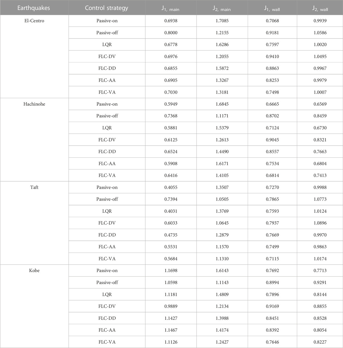
TABLE 2. Evaluation criteria of each building.
Conclusion
The performance of a semi-active control system for coupled building models with MR dampers has been investigated. Comparing seismic responses under uncontrolled and control strategies reveals that both passive and semi-active control systems can effectively reduce seismic responses. Nevertheless, the performance of the main structure is not identical during all earthquakes.
Based on the results of this study, following conclusion can be drawn:
1) The coupled buildings with base-isolation building and MR dampers, which are regarded as connecting dampers, are effective for seismic response reduction.
2) The performance under a semi-active control system varies depending on the type of feedback.
3) By utilizing the adaptive neuro-fuzzy inference system with the feedback of displacement and velocity, it can be observed that it is more effective under the pulse-like earthquake.
4) The performance of the displacement control is better than the absolute acceleration control. A significant decrease is observable under the control strategies.
5) The proposed semi-active control algorithm to operate the MR dampers can effectively reduce the response of the main structure during the ground motions.
6) In general, the proposed control algorithm of FLC-DV have the better performance in comparison with other control strategies for the main structure.
In spite of the fact that this study has successfully demonstrated that the proposed control algorithm has the significant reduction for the displacement control of the system, it has the certain limitation in terms of the acceleration control.
Consequently, it would be of interest to develop a more effective method in which ANFIS is integrated with other method that can efficiently adjust the parameters of the membership functions of ANFIS to alleviate both displacement and acceleration of the coupled buildings control system in the future.
Data availability statement
The raw data supporting the conclusions of this article will be made available by the authors, without undue reservation.
Author contributions
WT, Developed the method, formal Analysis, drafted the manuscript; MI, Supervision, revised and edited the manuscript.
Conflict of interest
The authors declare that the research was conducted in the absence of any commercial or financial relationships that could be construed as a potential conflict of interest.
Publisher’s note
All claims expressed in this article are solely those of the authors and do not necessarily represent those of their affiliated organizations, or those of the publisher, the editors and the reviewers. Any product that may be evaluated in this article, or claim that may be made by its manufacturer, is not guaranteed or endorsed by the publisher.
References
Al-Fahdawi, O., Barroso, L., and Soares, R. (2019). Adaptive neuro-fuzzy and simple adaptive control methods for attenuating the seismic responses of coupled buildings with semi-active devices: Comparative study. J. Soft Comput. Civ. Eng. 3. doi:10.22115/scce.2019.199731.1128
Bharti, S. D., Dumne, S. M., and Shrimali, M. K. (2010). Seismic response analysis of adjacent buildings connected with MR dampers. Eng. Struct. 32, 2122–2133. doi:10.1016/j.engstruct.2010.03.015
Bhaskararao, A. V., and Jangid, R. S. (2006). Seismic response of adjacent buildings connected with friction dampers. Bull. Earthq. Eng. 4, 43–64. doi:10.1007/s10518-005-5410-1
Bigdeli, K., Hare, W., and Tesfamariam, S. (2012). Configuration optimization of dampers for adjacent buildings under seismic excitations. Eng. Optim. 44, 1491–1509. doi:10.1080/0305215X.2012.654788
César, M. B., and Barros, R. C. (2016). ANFIS optimized semi-active fuzzy logic controllerfor magnetorheological dampers. Open Eng. 6. doi:10.1515/eng-2016-0075
Chang, C.-C., and Zhou, L. (2002). Neural network emulation of inverse dynamics for a magnetorheological damper. J. Struct. Eng. 128, 231–239. doi:10.1061/(asce)0733-9445(2002)128:2(231)
Dyke, S. J. (1996). Acceleration feedback control strategies for active and semi-active control systems: Modeling, algorithm development and experimental verification. PhD Thesis. Indiana: University of Notre Dame.
Dyke, S. J., Spencer, B. F., Sain, M. K., and Carlson, J. D. (1996). Modeling and control of magnetorheological dampers for seismic response reduction. Smart Mat. Struct. 5, 565–575. doi:10.1088/0964-1726/5/5/006
Fukumoto, Y., and Takewaki, I. (2017). Dual control high-rise building for robuster earthquake performance. Front. Built Environ. 3. doi:10.3389/fbuil.2017.00012
Gu, X., Yu, Y., Li, J., and Li, Y. (2017). Semi-active control of magnetorheological elastomer base isolation system utilising learning-based inverse model. J. Sound Vib. 406, 346–362. doi:10.1016/j.jsv.2017.06.023
Gu, X., Yu, Y., Li, Y., Li, J., Askari, M., and Samali, B. (2019). Experimental study of semi-active magnetorheological elastomer base isolation system using optimal neuro fuzzy logic control. Mech. Syst. Signal Process. 119, 380–398. doi:10.1016/j.ymssp.2018.10.001
Gu, Z. Q., and Oyadiji, S. O. (2008). Application of MR damper in structural control using ANFIS method. Comput. Struct. 86, 427–436. doi:10.1016/j.compstruc.2007.02.024
Hayashi, K., Fujita, K., Tsuji, M., and Takewaki, I. (2018). A simple response evaluation method for base-isolation building-connection hybrid structural system under long-period and long-duration ground motion. Front. Built Environ. 4, 2. doi:10.3389/fbuil.2018.00002
Jang, J.-S. R. (1993). Anfis: Adaptive-network-based fuzzy inference system. IEEE Trans. Syst. Man. Cybern. 23, 665–685. doi:10.1109/21.256541
Jayalakshmi, T., and Santhakumaran, A. (2011). Statistical normalization and back propagationfor classification. IJCTE, 89–93. doi:10.7763/IJCTE.2011.V3.288
Kim, H.-S. (2016). Seismic response control of adjacent buildings coupled by semi-active shared TMD. Int. J. Steel Struct. 16, 647–656. doi:10.1007/s13296-016-6030-0
Murase, M., Tsuji, M., and Takewaki, I. (2013). Smart passive control of buildings with higher redundancy and robustness using base-isolation and inter-connection. Earthquakes Struct. 4, 649–670. doi:10.12989/EAS.2013.4.6.649
Nakamura, T., Fujita, K., and Takewaki, I. (2021). A simple critical response evaluation method for base-isolation building-connection hybrid system under double impulse as representative of near-fault ground motion. Front. Built Environ. 7, 790584. doi:10.3389/fbuil.2021.790584
Ng, C.-L., and Xu, Y.-L. (2006). Seismic response control of a building complex utilizing passive friction damper: Experimental investigation. Earthq. Eng. Struct. Dyn. 35, 657–677. doi:10.1002/eqe.549
Ohtori, Y., Christenson, R. E., Spencer, B. F., and Dyke, S. J. (2004). Benchmark control problems for seismically excited nonlinear buildings. J. Eng. Mech. 130, 366–385. doi:10.1061/(asce)0733-9399(2004)130:4(366)
Seto, K., and Matsumoto, Y. (1999). “Active vibration control of multiple buildings connected with active control bridges in response to large earthquakes,” in Proceedings of the 1999 American Control Conference (Cat. No. 99CH36251), San Diego, CA, USA, 1007–1011. doi:10.1109/ACC.1999.7831922
Spencer, B. F., Dyke, S. J., Sain, M. K., and Carlson, J. D. (1997). Phenomenological model for magnetorheological dampers. J. Eng. Mech. 123, 230–238. doi:10.1061/(asce)0733-9399(1997)123:3(230)
Taniguchi, M., Fujita, K., Tsuji, M., and Takewaki, I. (2016). Hybrid control system for greater resilience using multiple isolation and building connection. Front. Built Environ. 2. doi:10.3389/fbuil.2016.00026
Uz, M. E., and Hadi, M. N. S. (2014). Optimal design of semi active control for adjacent buildings connected by MR damper based on integrated fuzzy logic and multi-objective genetic algorithm. Eng. Struct. 69, 135–148. doi:10.1016/j.engstruct.2014.03.006
Xu, Y. L., and Zhang, W. S. (2002). Closed-form solution for seismic response of adjacent buildings with linear quadratic Gaussian controllers. Earthq. Engng. Struct. Dyn. 31, 235–259. doi:10.1002/eqe.107
Yan, G., and Zhou, L. L. (2006). Integrated fuzzy logic and genetic algorithms for multi-objective control of structures using MR dampers. J. Sound Vib. 296, 368–382. doi:10.1016/j.jsv.2006.03.011
Yang, Z., Xu, Y. L., and Lu, X. L. (2003). Experimental seismic study of adjacent buildings with fluid dampers. J. Struct. Eng. 129, 197–205. doi:10.1061/(asce)0733-9445(2003)129:2(197)
Zhang, W. S., and Xu, Y. L. (1999). Dynamic characteristics and seismic response of adjacent buildings linked by discrete dampers. Earthq. Engng. Struct. Dyn. 28, 1163–1185. doi:10.1002/(sici)1096-9845(199910)28:10<1163::aid-eqe860>3.0.co;2-0
Keywords: semi-active control, adaptive neuro-fuzzy inference system, ANFIS, clipped-optimal control strategy, MR damper, coupled buildings control, base-isolation
Citation: Tai WC and Ikenaga M (2022) A semi-active control system in coupled buildings with base-isolation and magnetorheological dampers using an adaptive neuro-fuzzy inference system. Front. Built Environ. 8:1057962. doi: 10.3389/fbuil.2022.1057962
Received: 30 September 2022; Accepted: 01 December 2022;
Published: 14 December 2022.
Edited by:
Yunpeng Zhu, Queen Mary University of London, United KingdomCopyright © 2022 Tai and Ikenaga. This is an open-access article distributed under the terms of the Creative Commons Attribution License (CC BY). The use, distribution or reproduction in other forums is permitted, provided the original author(s) and the copyright owner(s) are credited and that the original publication in this journal is cited, in accordance with accepted academic practice. No use, distribution or reproduction is permitted which does not comply with these terms.
*Correspondence: Wei Chun Tai, azkxNDgyMEBrYW5zYWktdS5hYy5qcA==; Masahiro Ikenaga, bWlrZW5hZ2FAa2Fuc2FpLXUuYWMuanA=