Investigation of microtremors observed at historic masonry townhouse buildings after Nepal earthquake
 Yoichi Mukai
 Hayato Hoshino
 Naohiko Yamamoto
 Masaya Masui
 Anri Miyauchi
 Ram Prasad Suwal
- 1Department of Architecture, Graduate School of Engineering, Kobe University, Kobe, Japan
- 2Research Institute of Technology, Konoike Construction Co., Tsukuba, Japan
- 3Faculty of Human Life and Environment, Nara Women’s University, Nara, Japan
- 4Osaka Museum of Housing and Living, Osaka, Japan
- 5Hokuden Engineering Consultants. Co., Ltd., Japan, Toyama, Japan
- 6Department of Architecture, Nepal Engineering College, Bhaktapur, Nepal
The Gorkha earthquake in 2015 was a recent large-scale earthquake that caused severe damage to many historic masonry buildings in the Kathmandu Valley, Nepal. The authors conducted a visual inspection survey of seismically damaged buildings after the earthquake in the historic town district of Bhaktapur in the Kathmandu Valley. The first part of this paper reports the distribution of the historic masonry buildings for each damage level in the surveyed area. A concentrating zone of severely-damaged buildings was explicitly found in the damage-level distribution map. Almost half of all the surveyed buildings were severely damaged during the earthquake, and most of these were historic masonry townhouse buildings. In the second part, the ambient vibration characteristics of the conventional historic masonry buildings in Bhaktapur are investigated. Typical dwelling houses in a historic town district in Nepal, which generally formed terraced houses built around a courtyard, were targeted for the measurement. Thus, the influence of adjacent buildings, which makes it difficult to identify the predominant natural frequencies from building vibration measurements, was also observed. Microtremor measurements using two accelerometers were conducted at 11 historic masonry buildings to investigate the discrimination degree for identifying the predominant natural frequency of conventional townhouse buildings. The estimated primary natural frequencies of these buildings were compared with the results of the screening model analysis. The advantages of using the proposed screening model analysis to improve the uncertainty of the first natural frequency identification by the microtremor measurement are discussed. Additional measurements of the microtremors at 4 of the 11 measured buildings were conducted using a different location combination of the two acceleration sensors. The sensors were placed between two different floors, and the transfer functions of each floor were investigated to observe the predominant vibration components on the floors in the entire building. Moreover, the coherence values observing the in-plane correlation of the floor responses were also analyzed for the dataset measured at two points separated on the same floor. Finally, an effective method for measuring the microtremors is discussed to improve the assessment of the vibration characteristics of conventional historic masonry buildings in Nepal.
1 Introduction
The Nepal earthquake occurred on April 25, 2015. The epicenter was located in the eastern area of the Gorkha District at Barpak, Gorkha, and the hypocenter was at a depth of approximately 8.2 km (USGS, 2015). Many masonry buildings were seriously damaged in historic cities and towns in the Kathmandu Valley (Ohsumi et al., 2016; Yamada et al., 2016; Bhagat et al., 2018). The Nepal Disaster Risk Reduction Portal has reported the aggregate number of disaster victims (Nepal Disaster Risk Reduction Portal; as of 2022) to be 8,962 people killed, 22,302 injured, and 195 missing in all regions of Nepal. Furthermore, 775,782 buildings were destroyed, and 302,774 buildings were partially damaged. Approximately 95% of the completely destroyed buildings are regarded as low-strength masonry buildings constructed with low-quality materials for joints and bricks. However, reinforced masonry buildings with reinforced concrete (RC) frames were observed in less than 2% of destroyed buildings (National Planning Commission, Government of Nepal, 2016).
Many typical masonry buildings constructed in the historic style with wooden frames and brick walls have remained in the historic cities and towns in the Kathmandu Valley, which was included in the UNESCO World Heritage List as a cultural site in 1979. The historic townscape consists of traditional masonry houses along streets preserved in historic areas ruled by the former dynasties in Nepal, including Kathmandu, Lalitpur (Patan), and Bhaktapur (UNESCO, 2006). Most of the existing historic masonry buildings were constructed more than one hundred years ago; thus, these are thought to have experienced the major large earthquakes occurring nearby Nepal in the 20th century: the 1934 Bihar–Nepal earthquake (Mw 8.0), 1988 Udaypur earthquake (Mw 6.9) and 2015 Gorkha earthquake (Mw 7.8) (Bilham, 2004; Mugnier et al., 2013). The moment magnitude scale (Mw) of these earthquakes is quoted from the USGS Earthquake Hazards Program (U.S. Geological Survey; as of 2022). However, it is difficult to determine the current structural soundness of each building. The damage situations of these conventional historic masonry buildings have not been precisely evaluated, and histories of recovery or repair from seismic damage have rarely been recorded for the buildings. Structural soundness screenings of these historic masonry buildings are considered essential for preserving human lives and the traditional living environment from the expected seismic hazard in the near future.
Most conventional historic masonry buildings worldwide are considered to be constructed without a proper structural design process; thus, the structural performance of these buildings varies greatly. Furthermore, the quality of the construction materials and the mechanical performance of structural elements are not generally managed by industrial standards. The precision of the member dimension, jointing, or member position is not sufficiently secured during construction. These problems are likely to cause difficulties in determining the structural performance of historic masonry buildings. Researchers have recently attempted to estimate the dynamic structural performances of historic masonry buildings through numerical simulation analyses. Ahari et al. compared numerical analysis results using a simplified two-wall analysis model and a three-dimensional finite element method (FEM) model to analytically estimate the seismic behaviors of a historic masonry bazaar building in Iran (Ahari et al., 2011). Furukawa et al. conducted a numerical simulation using the refined distinct element method (DEM) modeling for a historic masonry building in Nepal and estimated the seismic performance of the target building (Furukawa et al., 2019). Parajuli et al. conducted compressive tests of brick masonry in mud mortar from monumental neoclassical buildings in Kathmandu Valley. The mechanical properties of brick masonry were validated by comparing the in-plane failure pattern of masonry walls using the refined DEM analysis. The results highlighted the dependence of material quality on the mechanical properties of masonry buildings and the importance of considering and evaluating discrepancies in mechanical properties at various locations in masonry constructions (Parajuli et al., 2020). Adhikari and D’Ayala reported the post-earthquake reconstruction process of a masonry building with stone-jointed mud mortar after the Nepal earthquake. Seismic performance validation was performed using applied element method (AEM) simulations (Adhikari and D’Ayala, 2020). Karanikoloudis and Lourenço conducted an FEM analysis for the structural assessment of the seismic vulnerability of a historic masonry church in Peru. In-situ inspection with dynamic and sonic testing was also conducted to validate the model parameters for the simulations (Karanikoloudis and Lourenço, 2018).
Most of these numerical modeling approaches assumed that the masonry walls or slabs, the composite material of brick and mortar, are equivalent homogeneous materials. The primary structural elements consist of a solid model to configure the shapes of the target structural members. Because computational simulation tools to conduct the analysis using a large number of elements have been developed and generalized recently, the primary purpose of these studies was to reproduce the accurate structural behaviors of the target structures using detailed numerical simulation models. The importance of detailed model analysis has been recognized in visualizing both the global and local behavior of the target structures and estimating the primary structural mechanism of existing constructions, whose characteristics have high uncertainty. Accordingly, physical tests clarifying the material constants and vibration characteristics are sometimes necessary when validating the reproducibility of numerical analysis.
However, these detailed simulations are limited to the structural assessment of very special or important buildings because of the high cost, effort, and skill required for performing the analysis. More reliable but versatile analytical approaches may be necessary when the structural assessments of many conventional masonry buildings are considered. Thus, a widely usable modeling investigation is regarded as a fundamental approach. The validation of the numerical simulation results has been commonly conducted through previous research to assess historic masonry buildings. Therefore, the importance of physical measurements in estimating the structural properties of existing target constructions has been highlighted. Bayraktar et al. reported the results of an ambient vibration test (AVT) and operational modal analysis conducted on a historical masonry bell tower in Turkey. Modal identification from the ambient vibration responses and the FEM analysis of the tower building were performed. The results indicated that the modal shapes using the solid model configuring the wall thickness and openings corresponded well with the measured results (Bayraktar et al., 2009). Parajuli et al. conducted a microtremor measurement in a 2-story historic masonry house building in Lalitpur, Kathmandu Valley, and investigated the dependency of wall openings on the identified predominant frequency (Parajuli et al., 2011). Furukawa et al. conducted microtremor measurements of a target masonry building in Nepal before and after the Nepal earthquake to identify practical vibration characteristics and validate the numerical simulation results (Furukawa et al., 2017). Considering the discussions in the previous studies, the numerical simulation results were validated by clarifying the structural material constant of the target buildings and confirming the reproducibility of the dynamic characteristics, for example, the predominant frequencies of the numerical model. Accordingly, an in-situ measurement of the structural vibration of the target buildings is considered an important process for valid numerical simulation results. Microtremor measurement is regarded as the conventional approach for portable assessment of the vibration characteristics of historic masonry buildings. However, the reliability and precision of the identification results are thought to be in the investigation stage through practical measurements. Therefore, the accuracy of the structural assessment should be improved by conducting numerous data collections in existing buildings and analyzing the measured data from various viewpoints. Furthermore, comparative evaluations are considered essential for exploring the various conditions of the measured buildings. For the structural assessment of screening vulnerable buildings among many uncertain targets, a measuring method capable of quickly performing may be necessary because sensing is conducted at many target buildings with limited time, workers, and equipment.
The research orientation of this study was directed toward practical demands for structural assessments. The first part of this paper describes the distribution map of buildings damaged by the 2015 Nepal earthquake. A field survey was conducted to observe damaged buildings in Bhaktapur, a historic city in the Kathmandu Valley. The typical broken pattern of historic masonry buildings in the survey area was observed, and the rates of severely damaged or collapsed buildings and the remaining buildings were investigated (Mukai et al., 2016). Microtremor measurements were then conducted at 11 residential masonry buildings in or near the survey area. These buildings were built using the historic construction method and existed before the 2015 Nepal earthquake. The measurements collected the microtremor data between the top floor and ground level of these 11 buildings. The first natural frequencies were identified by observing the FFT results of the measured data. The structural features and damage conditions after the earthquake are also summarized for each building. The results were screened by comparing the eigenvalue analysis of the simple evaluation model with the identified first natural frequencies.
Furthermore, to observe the vibration characteristics of the mid-floors of the buildings and the correlation of the in-floor responses, additional microtremor measurements were conducted in four selected buildings using a limited number of sensors (two accelerometers). The improvement in identifying the first natural frequencies by the microtremors is discussed by investigating these additional measurement results.
2. Seismic damage situation around the survey area after the earthquake in 2015
2.1 Overview of the survey area
Before the Gorkha earthquake, the authors started townscape documentation research of the historic urban area in Bhaktapur, the old capital city of one of the three major kingdoms of the medieval Kathmandu Valley. Bhaktapur is located approximately13 km in the east of Kathmandu, the capital city of Nepal, and there are many historic masonry buildings and traditional town streets that are well preserved. A field survey was conducted to determine the placement configurations of the public spaces and urban facilities in Bhaktapur. The purpose of this research was to categorize the developmental process of a typical urban courthouse and clarify the relevance between living-activity and dwelling locations (Kido et al., 2012; Masui et al., 2016; Yamamoto et al., 2016). Through these field surveys, the buildings layouts and dwelling demarcations of most townhouses were plotted on an area map centered on the eastern district of Bhaktapur before the Gorkha earthquake.
The seismic outbreak destroyed many masonry buildings in Bhaktapur constructed in a historic style during the 2015 Nepal earthquake. The locality was observed in the distribution of damaged buildings. Field observations were conducted in the eastern area of Bhaktapur, which corresponds to a part of the previously surveyed district, where many severely damaged masonry buildings were found. Figure 1 shows a map of the old town of Bhaktapur. The building survey was conducted in the area with a red-bold-lined rectangle of approximately 400 × 500 m around Dattatreya Square. The geological conditions of this area are also depicted on this map. The survey area was located between two rivers in the north and south. The composition of the ground is mentioned as silty clay, peat and plastic clay below the soil cover. For this reason, there is a high risk of liquefaction in this area, and the south-edge side of the site faces a slanted place towards the flood plain along the river. The Department of Mines and Geology of Nepal (DMG) has warned about landslide risk along the riverbanks and slopes (DMG, 1998).
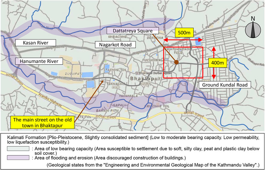
FIGURE 1. Location of the surveyed area and geological condition of the old town in Bhaktapur. (The background map was reprinted from the Google Maps website).
2.2 Damage category definition of masonry buildings and their distribution
About half a year after the Nepal earthquake, building-damage observation in the eastern area of the old town in Bhaktapur was conducted to clarify the distribution of damaged buildings. First, each building in the survey area was inspected and classified based on its degree of damage. Then, the building locations on the area map were marked according to their categorization from the four damage categories defined in Table 1. In this survey, the target buildings for damage observation were limited to buildings with more than two stories; thus, flat houses or warehouses and pergola-type single-story “Pati” buildings were excluded.
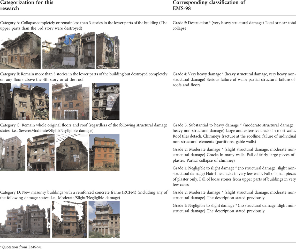
TABLE 1. Categorization of damage degree of buildings.
The damage grade of the European Macro-seismic Scale 1998 (EMS-98) is a well-known standard for describing the degree of damage to masonry buildings caused by earthquakes (Grünthal, 1998). However, the survey area was dense with buildings, and access to most buildings was difficult during the survey period. Therefore, the authors used a simplified assessment of the damage degree levels by modifying EMS-98, and the inspection items were narrowed down. The damage states were determined by observation of the front facade. Thus, the damage degree levels were classified into four categories: A, B, C, and D. Correspondence between the categorization in this study and the damage grade of the EMS-98 is considered as follows: Category A = Grade 5, Category B = Grade 4, Category C = Grades 1–3; these are for ordinary masonry buildings without any RC frame reinforcement. Furthermore, Category D = Grades 1–2 corresponds to masonry-infilled RC-framed (RCFM) buildings (including every type of RC frame support for masonry buildings; specifically, slabs, beams, columns or their combinations). Descriptions and photo examples for each category are provided in Table 1.
The distribution map of the damaged buildings is shown in Figure 2. In this figure, the buildings colored red were assessed as Category A. The orange-colored buildings were categorized as Category B. The green-colored buildings were assessed as Category C. Finally, the blue-colored buildings were assessed as Category D. Because it was difficult to approach some buildings during this field observation, detailed damage states, such as cracks on the walls, permanent buckling of the wall columns, and partial collapse of the building backside, could not be precisely identified. Therefore, the author must note that the damage distribution assessment results may contain some uncertain identifications.
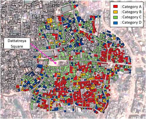
FIGURE 2. Distribution of damaged buildings in the survey area.
As shown in Figure 2, a belt-shaped zone is formed by the concentration of severely damaged buildings from the east end of the survey area to the south end. The number of buildings classified in each category is listed in Table 2. The damage states of 1978 buildings were evaluated through the field survey. It was confirmed that approximately half of all buildings surveyed in this area were in severely collapsed states (Categories A and B). The other half retained all original stories from before the earthquake (Categories C and D). When focusing on the survival rate of only historic masonry buildings (excluding the numbers in Category D, the RCFM buildings), it was found that 44.1% of the historic masonry buildings retained the original number of stories. Therefore, it is considered that the correlation of the rate of collapse of buildings is quite high for the surrounding ground states. The southern part of the survey area was connected to a downhill slope toward the valley along the south side river, and the possibility of amplifying surface ground motions during the earthquake was presumed to be one reason for the damage concentration in this zone.
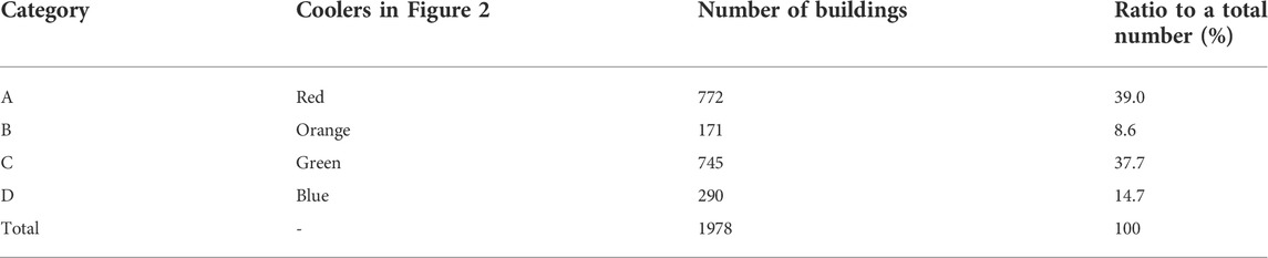
TABLE 2. Evaluated building numbers for each category in the survey area.
3 Microtremor measurement at the top floors of buildings
3.1 Outline of the measured buildings
In a previous study, the authors evaluated the vibration characteristics of masonry buildings in the survey area, and microtremor measurements of 22 buildings were performed in 2016 and 2017. These buildings were classified into three types: historical masonry buildings without RC frames (10 buildings), RCFM buildings that had already existed before the earthquake (8 buildings) and RCFM buildings constructed after the earthquake, including buildings under construction (4 buildings). Most buildings were located in or around the survey area, where building damage distribution was observed in 2015 (Takeuchi et al., 2018; Hoshino et al., 2019). Most measured buildings were typical residential townhouses, which were very similar in their building scale and geometrical configurations and connected to other buildings. The means of the predominant natural frequencies were approximately 4 Hz in both frontage and depth directions of the measured buildings. The variance of the measured values was around the range between approximately 2 and 8Hz. Therefore, it was considered that predominant frequencies observed in the microtremors of the measured buildings corresponded to overall global vibrations.
This study focused on historic masonry buildings without RC frames, and the microtremor measurement results for 11 buildings were evaluated. Measurements between the top and ground floor levels were conducted at the 11 buildings. Two acceleration sensors were used for the two measurements with time synchronization. The following analysis data were obtained from seven buildings in 2017 and four in 2018. The facade view of these measured buildings, the locational condition with adjoining buildings, and the sensor position and axial direction during the measurement are depicted in Figure 3. Most of the measured buildings were adjacent to other buildings at the two gable-end sidewalls, except Buildings 2, 6, and 9.
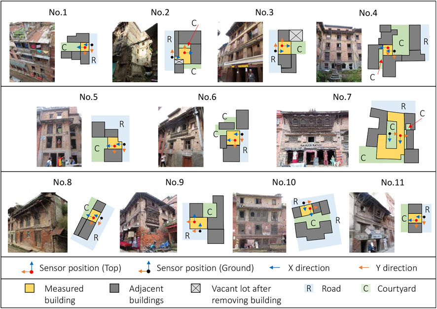
FIGURE 3. Building arrangement and exterior view of the measured buildings.
Table 3 shows the building information: floor numbers, damage condition after the earthquake, roof type, wall specification, eaves height, typical floor area, and total building weight. The “wall specification” refers to the state of the masonry brick and joint mortar at the exterior wall of the lowest story; the assigned classification notations are “BM” for brick masonry with mud mortar, poorly built; and “BMW” for brick masonry with mud mortar, well built. These abbreviations have been used in the study by Japan International Cooperation Agency (JICA) on earthquake disaster mitigation in the Kathmandu Valley (JICA, 2002).
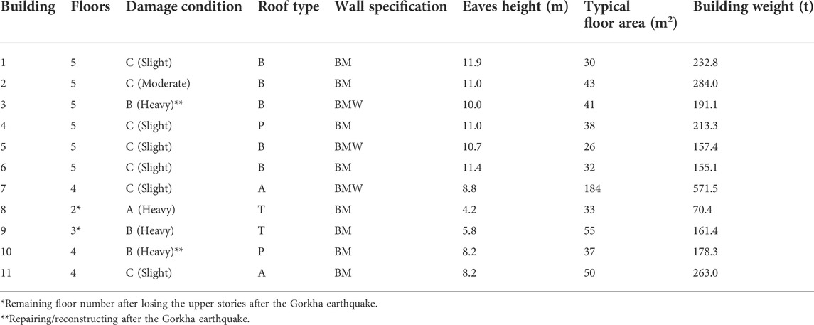
TABLE 3. Measured building information.
Typical townhouses before the 19th century were three-story buildings with gable roof trusses. After the 19th century, upper-floor extensions were observed in four-story buildings with gable roof trusses in urban areas. Remodeled buildings, in which the gable roof trusses were rebuilt into a flat roof balcony, and the story height has increased have appeared since the 1950s. The “Roof type” is the configuration of the building top. The notations correspond to the following: “A" is assigned to the historic gable roof truss, which was finished with a tiled roof in the traditional construction style. In this study, the attic floor in a gable roof space was regarded as the top floor of the building. “B" is assigned to the flat-roof balcony constructed using RC flat slab. In this study, the roof balcony floor was not included in the floor numbers of the building. “P" is assigned to the penthouse, which was created by rebuilding the gable roof trusses. The roof was covered with galvanized iron, and the penthouse space was used for residence or storage. “T" is assigned to the galvanized-iron top to repair the collapsed upper stories of the building temporarily. Buildings 8 and 9 were destroyed at their upper levels during the earthquake, and these parts were removed after the earthquake. The remaining lower stories of these buildings corresponded to this type at time of the measurement.
The “Damage condition” of the building after the Gorkha earthquake was clarified using the damage categories listed in Table 1. The buildings classified in Category C were reclassified to “Moderate” or “Slight” according to the damage or cracks observed on walls. The roof floors of Buildings 3 and 10, which collapsed during the Gorkha earthquake, were repaired after the Gorkha earthquake.
3.2 Measurement and data analysis process
Two acceleration sensors (HM-0013, IMV Corp., Japan) were used for the microtremor measurements. The sensors are available for 3-axis measurements, and their frequency range is from 0 Hz (direct current) to 100 Hz. The minimum resolution of the sensor was 1.192
FFT analyses were conducted on the measured data of the top and ground floor levels. A total of 214 = 16,384 sampling lengths were used from the measured time-series data, and these continuous data were divided into 211 length data segments with overlapping data fields of 210 sizes. The number of data segments
When the Fourier spectrum of the jth floor level using the ith data segment is expressed as
where the symbol "∼" indicates the complex conjugate value. The transfer functions (TF) of the top and ground floor levels were calculated using the following two methods.
Method 1:
Method 2:
The amplitude spectrums of the TFs based on Methods 1 and 2,
The amplitude spectrum of the TF of the top vs. ground floor levels
The curve smoothing in the frequency region was processed into the TF calculated using Eq. 5. In this study, the moving average filter using the window of the Gaussian function (data number =10 for the averaging window band) was applied for
Figure 4 depicts the three component waveform of the measured microtremors in Building 4. Measurements of the 11 buildings were conducted in the daytime. Vibrations accompanying the daily life of residents were considered in the measured vibrations. As seen at the bottom in Figure 4A, the influence of the activity of residents has mostly been observed in the Z (vertical) direction of the floor. Figure 5 depicts the TF and MATF of X (depth) and Y (frontage) directions for the 11 measured buildings. The candidate points of the first natural frequencies were detected by searching the local peak on the MATF curves in the range from 2.5 to 7.5 Hz. The inversed triangular marks "▼" indicate the possible points correlating to the first natural frequency of the measured building. In the followings, these values are expressed by
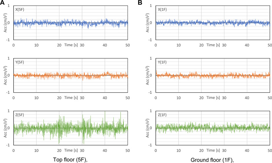
FIGURE 4. A part of the measured microtremors in Building 4. (A) Top floor (5F), (B) Ground floor (1F).

FIGURE 5. TF and MATF of the top vs. ground floor levels. (A) Building 1, (B) Building 2, (C) Building 3, (D) Building 4, (E) Building 5, (F) Building 6, (G) Building 7, (H) Building 8, (I) Building 9, (J) Building 10, (K) Building 11.
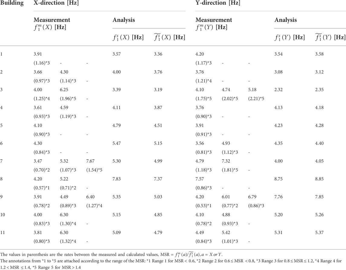
TABLE 4. First natural frequencies estimated by measurements and model analysis.
3.3 Measurement results vs. screening based on eigenvalue analysis using a simple examination model
Variances were observed in the certainty of the identified values of the first natural period of the measured building. Therefore, these values cannot directly indicate the measured structural performance or the soundness of the building. However, the building specifications, that is, story weight or height and effective wall length, might correlate with the fundamental vibration characteristics. Thus, a screening model analysis was performed, and the referential index qualifying the structural performance condition was obtained. Modal analyses were conducted to calculate the first natural frequency of each examination model, corresponding to the measured building configurations. The structural analysis software, midas-iGen (produced by MIDAS IT Japan Co.), was used for numerical modeling and simulation.
In this study, a referential index of the first natural frequency of each measured building is proposed to consider the difference in the vibration characteristics according to the building size, wall arrangement, and window-opening configuration on the walls. A simple examination model and its eigenvalue analyses were applied for this purpose. The required information regarding the building features was minimized for the proposed modeling process. The examination model consisted of multiple stories of mass and shear-spring type models, and the floor plane size was considered. Shear-spring elements were placed as a single homogeneous plate element at every single bay wall position arranged in each story. The influence of the floor deformation was excluded from the examination model because enough information about the floor stiffness was not obtained. Thus, all the floors were assumed to be rigid bodies in this study. Every floor of the examination model had three degrees of freedom (two-directional horizontal motion and rotational motion in the horizontal plane). The nodes of the plate elements for the walls were connected to their upper and lower floor planes, and the weights of the wall were equally distributed to every node position as the concentrated mass. To consider the influence of the size of the wall openings, the effective length ratio (ELR) was considered. The ELR was calculated for every bay with walls, and it was defined as the ratio between the total wall length, except the opening width, and the full bay length. The reduction in the shear stiffness of the walls is reflected by the contraction of the plate element’s thickness according to the ELR. The stiffness contribution to the out-of-plane direction of the walls was not considered for all plate elements in the examination model.
The estimation of the mechanical properties of the existing masonry buildings is an important step in the numerical evaluation of vibration characteristics of the existing masonry buildings. Young’s modulus and Poisson’s ratio of masonry are necessary to determine to perform an elastic numerical model analysis. Recently, the on-site assessments of the elastic modulus of the existing masonry buildings were performed using new techniques providing reliability and slight damage to walls. For example, Guadagnuolo et al. conducted the flat-jack tests in the masonry constructions of monumental and ordinary buildings in Southern Italy. However, masonry structures have substantial heterogeneity depending on materials and construction conditions. The modulus of elasticity estimated by Guadagnuolo’s tests was distributed in a wide range by a coefficient of variation from about 40 to 56% (Guadagnuolo et al., 2020). Parajuli’s research results on compressive tests for the core samples from the masonry wall of the existing historic building in Partan, Nepal, showed that the estimated Young’s modulus of the brick wall with mud mortar had a dispersion from 274 to 632 MPa (Parajuli, 2012).
In this study, Young’s modulus and Poisson’s ratio of the plate element were considered 310 N/mm2 and 0.2, respectively, which were determined referring to the previous experimental test reports of the masonry in Nepal. Mishra’s experimental results obtained the value of Young’s modulus for the examination model (310 N/mm2). Mishra conducted a diagonal compression test using masonry wall specimens at the Replace this word to Khwopa. Engineering College laboratory in Bhaktapur. They used walls with local hand-made bricks and mud mortar for the laboratory tests. The value of Poison’s ratio adopted in this study was also determined considering Mishra’s previous studies. The Poison’s ratio was estimated as the value close to an average between brick and mortar (approximately 0.238 for unit brick and 0.147 for mud mortar), which was obtained from Mishra’s tests; thus, Poisson’s ratio
Typical construction style floors of historic masonry buildings usually have two layers. The lower layer is a wooden frame composed of thin wooden boards covering the wooden beam and joist member support. The upper layer was built by piling mud on spread masonry bricks (Suwal, 2014). Most of the floor specifications of the measured buildings were of the traditional style, except for the RC slab of the roof balcony. The average thickness of the ordinary-style floors was approximately 200 mm for all the measured buildings. The unit volume weight of the masonry brick wall was estimated as 1.6 t/m3 to approximately calculate the total building weight. Previous research by Guadagnuolo et al. on structural investigations for the historic masonry buildings in Kathmandu Valley reported about 1.77 t/m3 for the unit volume weight of the masonry brick walls (Guadagnuolo et al., 2020). When considering the poor-quality condition of practical constructions, 1.6 t/m3 is used as approximately 90% of the reference value for calculation in this study. The unit volume weight of the floor slab and the ordinary roof-fired clay tiles were assumed to have the same value as the walls in this study. The weights of the other building elements, except for the structural parts (floors, walls, and roofs), were not considered in calculating the building weight.
The first natural frequencies of the examination model
The rate between the measured and simulated values of the first natural frequency (MSR),
4 Microtremor measurement on all floors of the buildings
4.1 Outline of the measurement procedure
Section 3 identified the first natural frequency of historic masonry buildings by conducting microtremor measurements. The measurements were performed using two accelerometers, and data were collected between the top and ground floor levels. Most buildings showed clear peaks in their MATF curves. However, some buildings had multiple peaks that were close to each other. Thus, the case of identifying the first natural period varied according to the differences in the measured building situations. The screening model analysis effectively assists in detecting the unmatching results or prospects of high-likelihood values in identifying the first natural frequency by building measurements. However, highly reliable measurements are required to preserve historic masonry buildings for structural assessment. In this section, an improved approach for determining the first natural frequency is investigated, assuming the practical measuring condition and the available sensor number limitation (two sensors were allowed for simultaneous measurement in this study).
Additional microtremor measurements were performed in 4 of the 11 buildings, measured in 2018: Buildings 4, 9, 10, and 11. Two accelerometers were available for use at that time. The measurement data, combinations of the top and any other floor level for these 4 buildings, were recorded. The section and plan drawings of the 4 buildings are shown in Figure 6. The story heights of these buildings were approximately the same. Buildings 4, 9, and 11 had three parallel masonry walls in the Y (frontage) direction in the 1st and 2nd stories (the internal wall on the 2nd story of Building 10 was removed at the time of remodeling). Interior walls located above the 3rd story were constructed using wooden frame structures. The walls in the X (depth) direction were not integrated with the frontage walls.
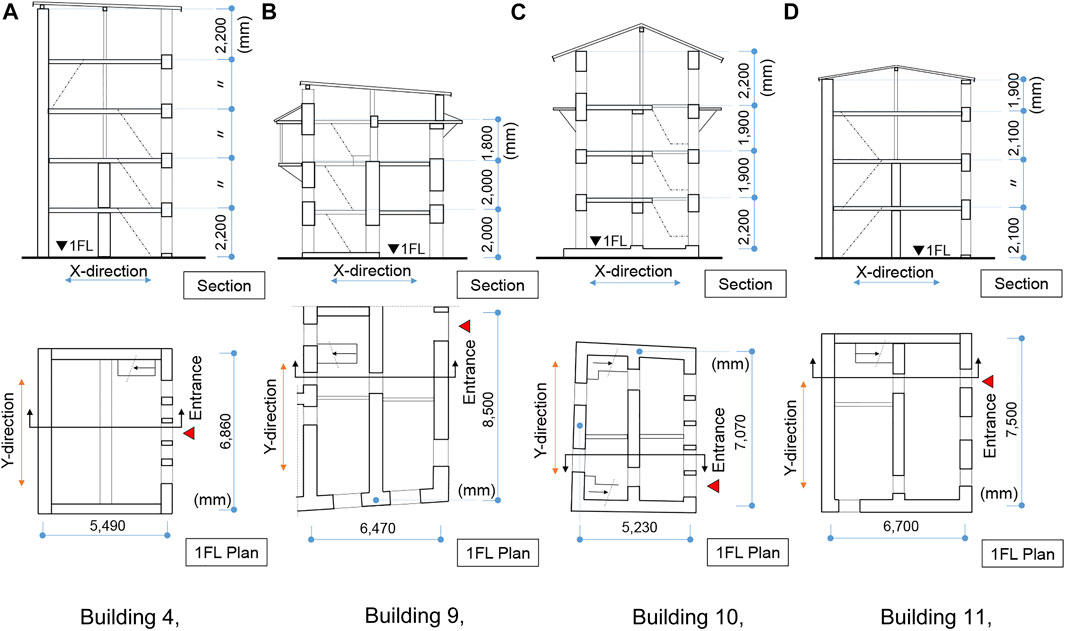
FIGURE 6. Section and plan of the measured buildings. (A) Building 4, (B) Building 9, (C) Building 10, (D) Building 11.
The roofs of Buildings 4 and 10 were covered with galvanized iron. The top floors of these buildings were remodeled to the penthouse spaces while extending the floor level. Building 4 was rebuilt before the earthquake, whereas Building 10 was rebuilt after the earthquake. Two owners occupied Building 10 separately, and the internal walls in the X (depth) direction were separated into two zones on the ground floor through the top floor. Therefore, the measurement of Building 10 was conducted only on the left-side zone of the front face. The earthquake destroyed the gable roof trusses of Building 9, but the garret space floor remained. Therefore, the garret space floor was regarded as the top (4th) floor of Building 9, and the measurements were performed there.
Figure 7 depicts the sensor positions on the floor where the measurements were performed. When the measurements between different floors were performed, the sensors were placed near the center of the floor position “C,” as seen in Figure 7. Every measurement was conducted by combining the top floor with other floor levels of the building. The data sampling period was 200 s under a 100 Hz data sampling interval. The MATFs between the upper floor and other floor levels were calculated using the measured data. At the time of measurement, two sensors were available. One sensor was placed on the top floor, and the other was moved to the combined floor. This is because the response correlation between the upper floors and the ground floor level was very low based on previous measurements. Furthermore, in addition to ground vibrations, various vibration input sources for the upper floors were considered. Thus, the correlation between floors mainly focused on this additional measurement. Figure 8 shows schematic drawings of measurement sequences to evaluate TF of every floor of Buildings 4 and 10. The positions of the fixed and the roving sensors are shown in these figures.
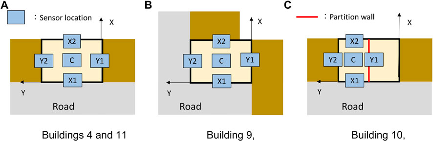
FIGURE 7. Sensor position notation at the measured building floor. (A) Buildings 4 and 11, (B) Building 9, (C) Building 10.
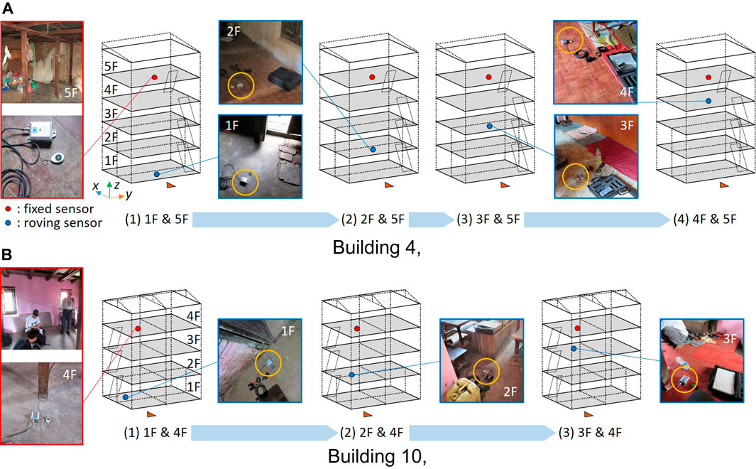
FIGURE 8. Location of the fixed and roving sensors for the measurements on all floors. (A) Building 4, (B) Building 10.
The process for calculating MATF is as follows. Consider the combined measurement of the top (Nth) floor level and the jth floor level. The top-floor number was N = 5 at Building 4 and N = 4 for Buildings 9, 10, and 11. The Fourier spectrum of the top-floor level and the jth floor level are given as
4.2 Investigation of measurement results
The MATF was also calculated using the procedures mentioned in Section 3.2. The MATF curves are shown at the top from 1) to 4) of Figure 9. The MATF of every floor above the ground floor level is plotted on a single figure. The MATF of the X (depth) and Y (frontage) directions correspond to the left 1) and right 2) figures. The first natural frequencies of the measured buildings are indicated by the inversed triangular marks "▼".
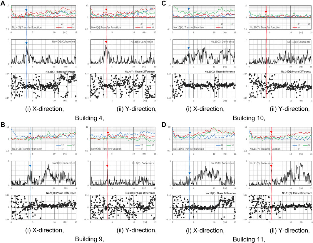
FIGURE 9. Additional microtremor measurement results. (upper row: MATF, middle row: coherence, and bottom row: phase difference.). (A) Building 4, (i) X-direction, (ii) Y-direction. (B) Building 9, (i) X-direction, (ii) Y-direction. (C) Building 10, (i) X-direction, (ii) Y-direction. (D) Building 11, (i) X-direction, (ii) Y-direction.
The rest of the evaluation results are shown in Figure 9 to clarify the results based on the MATF. The middle and bottom rows from 1) to 4) in Figure 9 correspond to the coherence and phase difference of the cross-spectrum, respectively. These results were obtained through additional measurements conducted on the top floor. The measurement at Building 11 was performed on the floor below the top floor because it was difficult to move around on the top floor. Two acceleration sensors were placed in two combinations, “X1″ and “X2″ or “Y1″ and “Y2″ on the top floor; the position notations are shown in Figure 7. The coherence and phase difference between the data from the two sensors were calculated. X-direction was observed under the combination of “X1″ and “X2,” and Y-direction was observed under the combination of “Y1″ and “Y2”. As shown in Figure 9, the coherence value increased, and the phase difference became nearly equal to zero, except for the Y-direction of Building 10, near the identified first natural frequency. Thus, superior correlations between two microtremors in the same direction of the same floor were confirmed in most of the measured buildings corresponding to the overall global vibration mode. These results demonstrated an applicable measurement procedure to improve the visibility of the structural modal identification in practical sensing situations. As the difference between Building 10 from the other buildings, the top floor of Building 10 was divided by internal walls in a depth direction. Thus, the sensor position was not placed near the exterior wall. At this point, the measurement conditions were different from those in the other buildings. Accordingly, the sensor near the exterior walls seems to capture global responses from in-floor measurements. Considering these additional measurement results, it seems adequate to perform a coherence analysis of the floor slab motions to validate the identification of the predominant natural frequency of the measured buildings.
5 Conclusion and discussions
This study evaluated the vibration characteristics of the conventional masonry buildings in Nepal built using the historic construction method and without the RC frame support. First, a post-earthquake survey around the historic town of Bhaktapur in Kathmandu Valley was conducted just after the 2015 Nepal earthquake, and the distribution of the damaged buildings in the survey area was clarified. Then, microtremor measurements of the historic masonry building in and around the survey area were conducted after the earthquake. Spectrum analysis results of the microtremors of these measured buildings were investigated. All measurements were performed by using two acceleration sensors. The following are the findings and discussions of this study.
1) The damage-level situations of historic masonry buildings caused by the earthquake were clarified based on the field observations in the specified area. As a result of the damage-level survey of 1978 buildings, a locally concentrated zone of severely damaged buildings was found in the building-damage-level distribution map. Considering the number of damaged/collapsed buildings and the remaining buildings, approximately half of the historic masonry buildings in the survey area were destroyed during the earthquake.
2) Microtremor measurements of historic masonry house buildings were conducted in Bhaktapur after the earthquake. Using the data measured at the top and ground floor levels of 11 buildings, the first natural frequency was evaluated from the calculated MATFs. Consequently, local peaks on the MATF curves were distinctly observed in most of the measured buildings. However, it was not always easy to identify the first natural frequency by monitoring the MATF curves; sometimes, the single peak was dominant, but often multiple peaks were close together, or no distinct peak appeared
3) The simplified multistory model was considered for the examination model analysis as the reference index in this study. The eigenvalue analysis results using the examination model and the first natural frequency identified by the measurement were compared. The standardized value considering the regionality was used as the material constant of wall elements in the examination models of all buildings. The MSR, a consistent ratio between the measured and calculated values of the first natural frequency, was adjusted to the distribution centered MSR = 1. Most buildings were screened in the range of
4) Additional measurements of microtremors were conducted between each floor and the top floor, between the front and rear sides on the top floor, and between the right and left sides on the top floor in 4 of the 11 measured buildings. The MATF of every floor was calculated, and the coherence and phase difference of the in-plane responses by the top floor’s measurements were investigated. Superior correlations between two microtremors measured on the same floor were observed near the predominant frequency in all the measured buildings. In this study, an applicable measuring procedure to improve the visibility of the structural identifications was demonstrated under practical sensing situations in conventional historic masonry buildings.
This research work reported the microtremor measurement results of historic masonry buildings, which existed in the area of the damage distributions surveys after the Gorkha earthquake. The results might contribute to a part of a helpful database considering the vibration characteristics of non-engineering buildings. This study also outlined the practical problems in the AVT for non-engineered masonry buildings. The results are required further verification with typological considerations. Furthermore, the modal analyses considering the variation of material properties and the construction style should be performed considering possible scenarios for each type of masonry building to validate the microtremor data. However, the number of measured buildings is insufficient to propose adaptable expertise for identifying the primary natural frequency of historic masonry buildings using microtremor measurements. The in-situ assessment using microtremors of historic masonry buildings will contribute an important role in the precision and reliability of numerical modelings. This should be enhanced by increasing the number of measured buildings and data accumulation. Moreover, the precise identification based on microtremor surveys of out-of-plane wall and in-plane floor motions should be discussed in future works because seismic damages to masonry buildings frequently depend on the out-of-plane failure of walls.
Data availability statement
The datasets supporting the conclusions of this article will be made available on request to the corresponding author.
Author contributions
YM supervised the research, conducted the field survey and data analysis, and wrote the journal paper document. HH conducted the microtremor measurement and data analysis. NY conducted the field survey and discussed the results. MM conducted the field survey and discussed the results. AM devised the survey plan and led the field survey. RS performed the building survey and the dimensional measurement of buildings and discussed the results.
Funding
Part of the present study is supported by the Grants-in-Aid for Scientific Research (JSPS KAKENHI: No. 15H05225 and No. 20H02330).
Acknowledgments
We acknowledge Prof. Mohan Moorti Pant of Khwopa Engineering College in Nepal for advising and assisting in the building survey and Masato Takeuchi, a graduate of Kobe University, for cooperating with our field survey after the earthquake. We also thank Sunil Jangam for many assistants visiting local buildings.
Conflict of interest
Author HH is employed by Konoike Construction Co. Author AM is employed by Hokuden Engineering Consultants. Co.
The remaining authors declare that the research was conducted in the absence of any commercial or financial relationships that could be construed as a potential conflict of interest.
Publisher’s note
All claims expressed in this article are solely those of the authors and do not necessarily represent those of their affiliated organizations, or those of the publisher, the editors and the reviewers. Any product that may be evaluated in this article, or claim that may be made by its manufacturer, is not guaranteed or endorsed by the publisher.
References
Adhikari, R. K., and D’Ayala, D. (2020). 2015 Nepal earthquake: Seismic performance and post-earthquake reconstruction of stone in mud mortar masonry buildings. Bull. Earthq. Eng. 18, 3863–3896. doi:10.1007/s10518-020-00834-y
Ahari, G. Z., Yamaguchi, K., Ninomiya, Y., and Miiyajima, M. (2011). “Analytical approach to seismic evaluation of a historical masonry building – tabriz bazaar in Iran,” in 6th International Conference of Seismology and Earthquake Engineering, 1–10.
Bayraktar, A., Türker, T., Sevım, B., Altuni¸sik, A. C., and Yildirim, F. (2009). Modal parameter identification of hagia sophia bell-tower via ambient vibration test. J. Nondestruct. Eval. 28, 37–47. doi:10.1007/s10921-009-0045-9
Bhagat, S., Buddika, H. A. D. S., Adhikari, R. K., Shrestha, A., Bajracharya, S., Joshi, R., et al. (2018). Damage to cultural heritage structures and buildings due to the 2015 Nepal Gorkha earthquake. J. Earthq. Eng. 22 (10), 1861–1880. doi:10.1080/13632469.2017.1309608
Bilham, R. (2004). Earthquakes in India and the himalaya: Tectonics, geodesy and history. Ann. Geophys. 47 (2/3), 839–858. doi:10.4401/ag-3338
Department of Mines and Geology (1998). Engineering and environmental geological map of the Kathmandu Valley. Scale 1, 50000.
Furukawa, A., Hanafusa, R., Kiyono, J., and Parajuli, R. R. (2019). Investigation of natural frequency reduction mechanism of a historic masonry building in patan following the 2015 Gorkha earthquake in Nepal. J. JAEE. 19 (8), 19. doi:10.5610/jaee.19.8_19
Furukawa, A., Kiyono, J., Parajuli, R. R., Parajuli, H. R., and Toki, K. (2017). Evaluation of damage to a historic masonry building in Nepal through comparison of dynamic characteristics before and after the 2015 Gorkha earthquake. Front. Built Environ. 3 (62), 1–16. doi:10.3389/fbuil.2017.00062
Government of Nepal (2022). Nepal disaster risk reduction portal. Available at: http://drrportal.gov.np/.
Grünthal, G. (1998). European macroseismic scale 1998: EMS-98. Bucharest, Romania: European Seismological Commission, 14–15.
Guadagnuolo, M., Aurilio, M., Basile, A., and Faella, G. (2020). Modulus of elasticity and compressive strength of tuff masonry: Results of a wide set of flat-jack tests. Build. (Basel). 1084, 84–18. doi:10.3390/buildings10050084
Hoshino, H., Takeuchi, M., Mukai, Y., Yamamoto, N., Masui, M., Miyauchi, A., et al. (2019). “Micro-tremor measurement of damaged masonry buildings in Bhaktapur after the 2015 Gorkha earthquake in Nepal,” in Proc. of 2nd International Conference on Earthquake Engineering and Post Disaster Reconstruction Planning, 292–301.
Japan International Cooperation Agency (JICA) (2002). The study on earthquake disaster mitigation in the Kathmandu Valley, kingdom of Nepal: Final report; vol. 3. -Main report (2/2): Earthquake disaster assessment and database system, 39. Available at: http://openjicareport.jica.go.jp/216/216/216_116_11685815.html.
Karanikoloudis, G., and Lourenço, P. B. (2018). Structural assessment and seismic vulnerability of earthen historic structures. Application of sophisticated numerical and simple analytical models. Eng. Struct. 160 (1), 488–509. doi:10.1016/j.engstruct.2017.12.023
Kido, A., Yamamoto, N., Masui, M., and Takeuchi, Y. (2012). Study on formation of urban tissue in Bhaktapur in Kathmandu Valley, Nepal. Jnl. Sci. Engg. 1, 1–16. doi:10.3126/jsce.v1i0.22488
Masui, M., Yamamoto, N., Takehashi, K., Hamaoka, A., Miyauchi, A., Tanaka, M., et al. (2016). Exterior design elements of townhouses and their distribution in and out of UNESCO's World cultural heritage monument zone in Bhaktapur. Proc. Int. Conf. Earthq. Eng. Post Disaster Reconstr. Plan. 2, 147–157.
Mishra, C., Yamaguchi, K., Endo, Y., and Hanazato, T. (2018). Mechanical properties of components of Nepalese historical masonry buildings. Proc. Int. Exch. Innovation Conf. Eng. Sci. (IEICES) 4, 118–123.
Mugnier, J. L., Gajurel, A., Huyghe, P., Jayangondaperumal, R., Jouanne, F., and Upreti, B. (2013). Structural interpretation of the great earthquakes of the last millennium in the central Himalaya. Earth-Science Rev. 127, 30–47. doi:10.1016/j.earscirev.2013.09.003
Mukai, Y., Takeuchi, M., Hoshino, H., Yamamoto, N., Masui, M., Miyauchi, A., et al. (2019). “Observation of reconstruction situation in the old town area in Bhaktapur damaged by the 2015 earthquake,” in Proc. of 2nd International Conference on Earthquake Engineering and Post Disaster Reconstruction Planning, 468–477.
Mukai, Y., Yamamoto, N., Masui, M., and Miyauchi, A. (2016). Observation of damaged buildings and the distribution on the south east area of the old town in Bhaktapur. Proc. Intnl. Conf. Earthq. Eng. Post Disaster Reconstr. Plan. 2, 236–243.
National Planning Commission, Government of Nepal (2016). Nepal earthquake 2015 post disaster needs assessment. A, 4. Available at: https://npc.gov.np/images/category/PDNA_Volume_A.pdf.
Ohsumi, T., Mukai, Y., and Fujitani, H. (2016). Investigation of damage in and around Kathmandu Valley related to the 2015 Gorkha, Nepal earthquake and beyond. Geotech. Geol. Eng. 34, 1223–1245. doi:10.1007/s10706-016-0023-9
Parajuli, H. R. (2012). Determination of mechanical properties of the Kathmandu World Heritage brick masonry buildings. Proc. 15th World Conf. Earthq. Eng. (15WCEE) 3139, 1–10.
Parajuli, H. R., Kiyono, J., Tatsumi, M., Suzuki, Y., Umemura, H., Taniguchi, H., et al. (2011). Dynamic characteristic investigation of a historical masonry building and surrounding ground in Kathmandu. J. Disaster Res. 6 (1), 26–35. doi:10.20965/jdr.2011.p0026
Parajuli, R. R., Furukawa, A., and Gautam, D. (2020). Experimental characterization of monumental brick masonry in Nepal. Structures 28, 1314–1321. doi:10.1016/j.istruc.2020.09.065
Suwal, R. P. (2014). Newari building construction technology: A case of vernacular residential dwelling of Bhaktapur city. Urban Ethos, Regional Urban Planners' Soc. Nepal 3, 33–39.
Takeuchi, M., Hoshino, H., Mukai, Y., Yamamoto, N., Masui, M., and Miyauchi, A. (2018). On study for damage detection of non-engineered masonry structures - micro-tremor measurement of damaged buildings by the 2015 Gorkha Earthquake in Nepal. Proc. of the 7th World Conference on Structural Control and Monitoring (7WCSCM), 2517–2527.
The U.S. Geological Survey (2022). The USGS earthquake hazards Program. Available at: https://earthquake.usgs.gov/.
UNESCO (2006). Heritage homeowner's preservation manual - Kathmandu Valley World heritage site, Nepal. Available at: https://unesdoc.unesco.org/ark:/48223/pf0000152020.
United States Geological Survey (USGS) (2015). M 7.8 - 67 km NNE of bharatpur, Nepal. Available at: http://earthquake.usgs.gov/earthquakes/eventpage/us20002926#scientific_finitefault.
Yamada, M., Hayashida, T., Mori, J., and Mooney, W. D. (2016). Building damage survey and microtremor measurements for the source region of the 2015 Gorkha, Nepal, earthquake. Earth Planets Space 68 (117), 117–118. doi:10.1186/s40623-016-0483-4
Keywords: Gorkha earthquake, historic masonry townhouse building, microtremor measurement, eigenvalue analysis, soundness screening, performance assessment
Citation: Mukai Y, Hoshino H, Yamamoto N, Masui M, Miyauchi A and Suwal RP (2022) Investigation of microtremors observed at historic masonry townhouse buildings after Nepal earthquake. Front. Built Environ. 8:918960. doi: 10.3389/fbuil.2022.918960
Received: 13 April 2022; Accepted: 26 July 2022;
Published: 31 August 2022.
Edited by:
Yves Reuland, ETH Zürich, SwitzerlandReviewed by:
Rishi Ram Parajuli, University of Bristol, United KingdomMukunda Bhattarai, Government of Nepal, Nepal
Copyright © 2022 Mukai, Hoshino, Yamamoto, Masui, Miyauchi and Suwal. This is an open-access article distributed under the terms of the Creative Commons Attribution License (CC BY). The use, distribution or reproduction in other forums is permitted, provided the original author(s) and the copyright owner(s) are credited and that the original publication in this journal is cited, in accordance with accepted academic practice. No use, distribution or reproduction is permitted which does not comply with these terms.
*Correspondence: Yoichi Mukai, ymukai@port.kobe-u.ac.jp