Open-source simulation of strongly-coupled fluid-structure interaction between non-conformal interfaces
 Nicolette S. Lewis1*
  Andrew O. Winter2 Justin Bonus3
  Michael R. Motley4 Marc O. Eberhard5 Pedro Arduino6 Dawn E. Lehman7
- 1Ph.D. Candidate, Department of Civil & Environmental Engineering, University of Washington, Seattle, WA, United States
- 2Affiliate Instructor, Department of Civil & Environmental Engineering, University of Washington, Seattle, WA, United States
- 3Ph.D. Candidate, Department of Civil & Environmental Engineering, University of Washington, Seattle, Italy
- 4John R. Kiely Endowed Associate Professor, Department of Civil & Environmental Engineering, University of Washington, Seattle, WA, United States
- 5Professor, Department of Civil & Environmental Engineering, University of Washington, Seattle, WA, United States
- 6H.R. Berg Endowed Professor, Department of Civil & Environmental Engineering, University of Washington, Seattle, WA, United States
- 7Testing Laboratory, Director of Large-Scale Structural Engineering, Department of Civil & Environmental Engineering, University of Washington, Seattle, WA, United States
Design code-based “life-safety” requirements for structural earthquake and tsunami design offer reasonable guidelines to construct buildings that will remain standing during a tsunami or seismic event. Much less consideration has been given to assessing structural resilience during sequential earthquake and tsunami multi-hazard events. Such events present a series of extreme loading scenarios, where damage sustained during the earthquake influences structural performance during the subsequent inundation. Similar difficulties exist with respect to damage sustained during tropical events, as wind and fluid loading may vary with structural response or accumulated damage. To help ensure critical structures meet a “life-safety” level of performance during such multi-hazard events, analysis software capable of simulating simultaneous structural and fluid dynamics must be developed. To address this gap in understanding of non-linear fluid-structure-interaction (FSI), an open-source tool (FOAMySees) was developed for simulation of tsunami and wave impact analysis of post-earthquake non-linear structural response of buildings. The tool is comprised of the Open-source Field Operation And Manipulation software package and OpenSeesPy, a Python 3 interpreter of OpenSees. The programs are coupled via preCICE, a coupling library for partitioned multi-physics simulation. FOAMySees has been written to work in a Linux OS environment with HPC clusters in mind. The FOAMySees program offers a partitioned conventional-serial-staggered coupling scheme, with optional implicit iteration techniques to ensure a strongly-coupled two-way FSI solution. While FOAMySees was developed specifically for tsunami-resilience analysis, it may be utilized for other FSI applications with ease. With this coupled Computational Fluid Dynamics (CFD) and Finite Element Analysis (FEA) program, tsunami and earthquake simulations may be run sequentially or simultaneously, allowing for the evaluation of non-linear structural response to multi-hazard excitation.
1 Introduction
Design code-based “life-safety” requirements for structural earthquake and tsunami design offer reasonable guidelines to construct buildings that will remain standing during a tsunami or seismic event. Much less consideration has been given to assessing structural resilience during sequential earthquake and tsunami multi-hazard events. Such events present a series of extreme loading scenarios, where damage sustained during the earthquake influences structural performance during the subsequent inundation. Similar difficulties exist with respect to damage sustained during tropical events, as wind and fluid loading may vary with structural response or accumulated damage. To help ensure critical structures meet a “life-safety” level of performance during such multi-hazard events, analysis software capable of simulating simultaneous structural and fluid dynamics must be developed. Additionally, such a program must not only account for initial earthquake damage, but also the interplay of fluid-induced forces and the motion of structures on which they act. This integrated approach of analysis of cascading hazards will allow engineers to better represent the physical conditions and expected conditions, enabling more resilient designs for critical structures.
To address this gap in understanding of non-linear fluid-structure-interaction (FSI), an open-source tool (FOAMySees) was developed for simulation of tsunami and wave impact analysis of post-earthquake non-linear structural response of buildings. The tool is comprised of the Open-source Field Operation And Manipulation (OpenFOAM, Weller et al., 1998) software package and OpenSeesPy (Zhu et al., 2018), a Python 3 interpreter of OpenSees (McKenna et al., 2010). The programs are coupled via preCICE (Bungartz et al., 2016), a coupling library for partitioned multi-physics simulation. FOAMySees has been written to work in a Linux OS environment with HPC clusters in mind. The FOAMySees program offers a partitioned conventional-serial-staggered coupling scheme, with optional implicit iteration techniques to ensure a strongly-coupled two-way FSI solution. While FOAMySees was developed specifically for tsunami-resilience analysis, it may be utilized for other FSI applications with ease. With this coupled Computational Fluid Dynamics (CFD) and Finite Element Analysis (FEA) program, tsunami and earthquake simulations may be run sequentially or simultaneously, allowing for the evaluation of non-linear structural response to multi-hazard excitation.
1.1 Research motivation
1.1.1 Numerical methods for fluid-structure interaction simulation
Several commercial packages with non-linear FSI capabilities are currently available, with a long-standing history of validation and community support (see LS-Dyna, STAR-CCM+, ABAQUS, COMSOL, etc.). Though these programs have been shown to be capable of solving complicated multiphysics problems with various coupled-numerical methodologies, the large barriers to entry associated with these commercial packages make these programs undesirable for research purposes. These barriers to entry include costs of licensing of the commercial codes and overhead for pre-processing and post-processing software packages, inflexibility of the sub-routines making solution of specialized problems complicated, as well as lack of transparency of the source codes. While suitable for solution of a broad range of fluid-structure interaction problems and have been used extensively in numerical and experimental studies of civil engineering structures, these programs each have drawbacks and none of the programs listed have been specifically developed for the purposes of civil/structural engineering, making earthquake analysis a challenge with many of these codes. A list of commonly-utilized parallelized software programs for Civil/Structural engineering along with their capabilities is shown in Table 1.
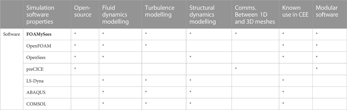
TABLE 1. Simulation capabilities for various parallelized software programs utilized for non-linear computational continuum mechanics.
Methods currently exist to couple open-source finite element codes (Deal-II, CalculiX, FENiCs, etc.) with computational fluid dynamics codes (see preCICE, associated adapters), but none of the existing commercial structural mechanics solvers that have been coupled with a fluid dynamics solver allow for representation of three-dimensional geometries within the fluid domain with one-dimensional, 6 degree of freedom structural beam elements. Such methods are currently in development which utilize an unstructured polyhedral finite volume method for solution of the structural deformation of modelled structures within Solids4Foam, an open-source fluid-structure interaction toolkit available for OpenFOAM. Despite the finite volume method offering high accuracy in solution of structural mechanics problems, this is a developing field of research and the finite volume method (unlike the finite element method) has not been extensively validated for earthquake engineering purposes. While strongly-coupled software programs capable of performing non-linear fluid-structure interaction of deformable bodies along with turbulence modelling within the fluid domain exist currently, few are open-source, and of those that are open-source, all utilize structural analysis software programs, which are not commonly utilized for the purposes of non-linear time history analysis of civil engineering applications and/or are geared toward conjugate heat transfer analysis rather than non-linear fluid-structure interaction.
1.1.2 Impetus for research
It is assumed that for very small deformations without periodicity a CFD model with non-slip velocity boundary conditions will suffice in determining applied force from impinging fluids, but for cases where displacements involve resonant vibration of a structure or where a structure possesses insufficient stiffness in particular degrees of freedom to resist incoming forces, the change in structural position and velocity within a flow can have a much more noticeable effect on fluid behavior and forces. In the case of larger deflections, or in the case of fluid-excited structural vibrations, fluid forces and their direction of application can result in changes of the pitch or position of the surfaces upon which they impinge, possibly leading to changes in loading. For tall, slender structures or structures with long spans such as bridges or highways, small changes in rotation at connections can result in large displacements of components of the structure. For example, a wide bridge with a long span could experience twisting of the bridge deck along the axis of its span, changing the position of the leading edge of the bridge deck structure within a flow transverse to the bridge span and the angle of inclination of the deck with respect to the flow. Furthermore, frequency based interactions between the structure and loading from surrounding flows can result in resonance between the structure and the vortexes shed in the wake of the structure, leading to vortex induced vibration.
In order to determine actual forces and impulses imparted from tsunami inundation events upon structures post-earthquake, expanding the extents of numerical analyses to realistic length scales of design structures subjected to tsunamis is necessary to accurately simulate structural deformations due to wave impingement and periodic fluid forcing from post-impact inundation flow. Additionally, since the feasibility and costs of experimental methods are prohibitive at full scale, utilizing numerical methods such as CFD for the determination of tsunami demands on structures at full scales presents the most economical alternative as well. By validating numerical models of experiments conducted at a reduced scale, validated numerical models may be used to simulate events at full scale in order to assess the accuracy of design equations and make recommendations for improvements. Thus identifying compatible combinations of CFD and FEM software is crucial to realizing full-scale simulations of consecutive earthquake and tsunami multi-hazard events.
Bearing these considerations in mind, OpenSees and OpenFOAM were selected for this research as the FEM and CFD simulation software, respectively. OpenSees is commonly used for non-linear FEM analysis of structures, particularly for earthquake simulation and hysteretic analysis of structures. OpenSees has a long-standing history in the civil engineering field and has been validated against experimental results countless times, providing reasonable confidence in the accuracy of the program when utilizing it for non-linear structural mechanics and dynamics. Similarly, OpenFOAM is used within the civil engineering community for CFD simulation of wind and water hazards, and has been validated against experiments involving hydrodynamic impact with great accuracy (Douglas and Nistor, 2014; Douglas et al., 2015; Motley et al., 2016; Wong, 2015; Sarjamee et al., 2017a; Sarjamee et al., 2017b; Qin et al., 2018; Qin, 2019; Winter 2019; Croquer et al., 2022; Elsheikh et al., 2022a; Elsheikh et al., 2022b; Liu et al., 2022).
OpenFOAM and OpenSees are both free, scalable, and plenty of example cases exist for both codes, which allows engineers to utilize the tools handily and learn through trial and error. The proposed application programming interface that couples OpenFOAM and OpenSees will assist engineers in analysis of structures subject to cascading hazards by offering a methodology for determining earthquake and tsunami forces at realistic scales while accounting for accumulated damage and non-linear fluid-structure interaction; this is particularly of importance when testing prototypical structures is not feasible or when experimental results from small-scale tests cannot be extrapolated accurately beyond their test-scales. Thus, the intention of this research is to expand the current capabilities of these open-source modelling methodologies such that they may be utilized to simulate full-scale damaged-state structural responses to non-linear fluid loading, and to validate the program against analytical and experimental test cases.
1.1.3 Scope of research
FOAMySees, an application programming interface (API) to allow for strongly-coupled FSI between OpenFOAM and OpenSeesPy, was developed to address the gaps in simulation capability described in the previous section. FOAMySees shows strong correlation with other FSI simulation software when benchmarked against analytical test cases. FOAMySees allows for any element formulation within OpenSeesPy to be utilized and coupled with a CFD simulation for the purposes of two-way strong fluid-structure interaction. Furthermore, the capabilities of FOAMySees allow for either preliminary or concurrent simulation of seismic excitation of structures with the OpenFOAM simulation, opening the possibility of simulation of non-linear structural response to multi-hazard events. The API is written such that users may build and implement any OpenSeesPy model, utilizing it for FSI analysis, before, during, or after additional forcing time histories as defined by the user. The program capabilities are intended to be of use to the civil engineering community to assist in the understanding of multi-hazard analysis and design of resilient structures. In particular, the capabilities of the program support high-fidelity CFD analyses of tsunami bore impact and inundation loading applied to non-linear post-yield multiple degree of freedom finite element models, allowing for the investigation of non-linear structural system responses to extreme hydrodynamic loading.
1.2 Computational mechanics methodologies
1.2.1 Computational fluid dynamics—OpenFOAM
Fluid modelling was completed using computational fluid dynamics (CFD) with the Open-source Field Operation And Manipulation (OpenFOAM) (Weller et al., 1998) software package, namely, OpenFOAM Foundation’s OpenFOAM.org—Version 8. OpenFOAM is a collection of C++ libraries that may be compiled to create individual applications, which are broadly categorized as either solvers or utilities. Cases examined here were simulated using the olaFlow solvers (Higuera, 2018), an open-source project developed within the OpenFOAM framework which solves the three-dimensional Volume Averaged Reynolds Averaged Navier Stokes equations (VARANS) using the finite volume discretization, allowing for the simulation of physically correct two-phase incompressible fluids. Additionally, olaFlow provides wave generation and active absorption functionality, which is useful for coastal engineering applications including tsunami-like wave generation. In cases when pure fluid phases are modeled where porosity is neglected, the VARANS equations utilized within olaFlow are reduced to the classical RANS equations utilized in the standard OpenFOAM application interFoam, from which the solvers for olaFlow were derived. Since porosity effects were not included in this study, similar CFD modelling procedures to those conducted by Motley et al. (2016) were performed for the following analytical correlation studies. OpenFOAM patch boundary conditions utilized in this study are listed in Table 2.
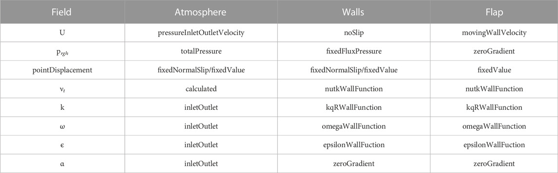
TABLE 2. Model boundary conditions for all field variables.
1.2.2 Modelling of multi-phase air-water mixture
The two incompressible phases (water and air) are tracked using the Volume of Fluid (VOF) technique to represent complex free surface configurations Hirt and Nichols (1981). An indicator function α is defined for the volume fraction of the two-phase fluid, which has a value of 1.0 corresponding to regions occupied by one phase, in this case water (ρ = 1, 000 kg/m3, ν = 1.0 × 10⁻⁶ m/s2), and a value of 0.0 for the other, in this case air (ρ = 1.22 kg/m3, ν = 1.48 × 10⁻⁵ m/s2), where ρ = mass density of the fluid; and ν = kinematic viscosity. Intermediate values indicate cells contain a mixture of water and air, where the free-surface between the fluids is not resolved explicitly. Where free-surface tracking was necessary in this study, a volume fraction of 0.5 was used to identify an approximate free-surface. The cell’s fluid phase fraction is represented by a scalar field with the variable, α. Furthermore, the VOF method assumes the fluid phases are immiscible, where each phase remains largely separate from one another, which is reflected by the fact that a single set of continuity and momentum governing equations are solved for both fluids, as opposed to Eulerian Multiphase (EMP) methods, which fully resolve phase interactions by incorporating interaction models and solving separate sets of continuity and momentum equations for each fluid phase.
1.2.3 Mesh motion in openFOAM
Motion of FSI interfaces for the present study is handled within OpenFOAM by the displacementLaplacianFvMotionSolver Class, which calculates the near field cell displacements required to satisfy a Laplacian diffusivity scheme specified by the user. This allows for smooth motion and deformation of the entire mesh during movement of boundary patches. Many other options for solution of cell deformation exist within OpenFOAM; however, the current coupling methodology only utilizes displacementLaplacian based mesh motion. As such, a discussion of alternative mesh motion techniques within OpenFOAM are omitted here for brevity. The displacementLaplacian finite volume motion solver only requires the displacement field at the boundary patch be specified either in memory or within the case files. This is handled dynamically in memory by the proposed coupling method, allowing real-time updates of the patch deformation during coupled fluid-structural analysis. Explanation of the displacement Laplacian methodology for finite volume method mesh motion is available in the original paper by Jasak and Tukovic (2006). For more detailed information on dynamic mesh capabilities within OpenFOAM, see Jasak (2009).
1.2.4 Computational solid mechanics—openSeesPy
OpenSeesPy (Zhu et al., 2018) is a Python language interpreter for the OpenSees (McKenna et al., 2010) finite element analysis framework. OpenSees is structured in a modular manner. Various industry standard non-linear solution algorithms are available, along with validated non-linear constitutive models and element formulations. Originally developed for the Pacific Earthquake Engineering Research (PEER) Center, OpenSees allows for the implementation of staged analyses of various types. Initial gravity and seismic analysis are conducted after creation of the finite element model within standard Python routines for OpenSeesPy. Due to the flexibility of OpenSees, sequential analysis of earthquake loading and tsunami loading to structures may be implemented readily. For implementation of a fluid-structure interaction analysis, particle finite element methods (PFEM) have been developed for OpenSees; however, PFEM in OpenSees is designed to solve fluid flow problems without considering turbulence modeling. Fluid-structure interaction within the present study is handled within OpenSees with an additional solution loop after initial analysis is complete, obtaining fluid forces from an OpenFOAM simulation running in parallel to the OpenSees simulation. This loop functions as a listener from the coupling driver, controlling the communication of nodal forces and displacements to and from the coupling interface software. Python module commands not included within the OpenSeesPy library are utilized for this loop, and are listed and explained in detail in Section “Usage of preCICE Python Language Bindings.”
1.2.5 Coupling methodology—preCICE
preCICE (Bungartz et al., 2016) is a library developed for the purpose of coupling multiphysics simulations in a partitioned method, utilizing iteration to ensure interface acceleration convergence between coupled surfaces and maintain stability. The approach allows for recovery of the coupling solution as if the problem were to be solved wihtin a single program through use of a partitioned “black box” approach and running coupled applications in parallel. The library functions by transferring data arrays between coupling partners for serial or parallel computation of fully-coupled solutions between codes. Convergence measures, data transfer, timestep iteration, and surface-to-surface mapping between coupling partners are managed by the preCICE library. These surface-to-surface mappings are most generally handled with radial basis function (RBF) mesh interpolation from the source mesh to a destination mesh.
1.2.6 preCICE adapters
preCICE is structured in a modular manner, with applications interfacing with the preCICE library via API function calls, which allow access to the routines of the library. Applications may be “plugged-in” to the preCICE library coupling routines by means of a coupling “adapter.” These adapters interface with the coupled program, taking data from the program and passing it to the preCICE library routines to be utilized in a manner specified by the user through configuration files. preCICE offers many adapters for open-source finite element and finite volume codes; however, many of these codes have not been validated for civil/structural engineering applications, and are not optimized to allow for a structural engineer to pick up and readily utilize them for engineering design purposes.
The preCICE API function calls are available in many languages via bindings. These bindings allow for usage of the preCICE library within code written in the language shared by the bindings, and offer flexibility for users to implement their own scripts and code for dynamically or temporally assigning boundary conditions within a desired numerical simulation.
1.2.7 Usage of preCICE python language bindings
Calls to the preCICE API are managed through a precice.Interface() object. This object has various classes that control data communication and solver progression. The classes of precice.Interface utilized in FOAMySees include:
precice.Interface
|−>.get_dimensions ()
|−>.initialize ()
|−>.initialize_data ()
|−>.is_read_data_available ()
|−>.is_coupling_ongoing ()
|−>.read_block_vector_data ()
|−>.write_block_vector_data ()
|−>.finalize ()
|−>.is_action_required ()
|−>.mark_action_fulfilled ()The latter two call upon the following preCICE action objects to return Boolean values:action_write_initial_data ()action_write_iteration_checkpoint ()action_read_iteration_checkpoint ()
A simplified version of initialization routines for FOAMySees along with their associated preCICE python language binding commands are shown in Figure 1A. The precice.Interface class and sub-classes are utilized within the main solution loop of FOAMySees to control the progression of the solution and manage iteration of OpenSeesPy until preCICE determines the coupling residual tolerance has been met. A simplified version of the main solution loop is shown schematically in Figure 1B. Calls to preCICE API functions are highlighted in orange, whereas the functions themselves are shown in blue.
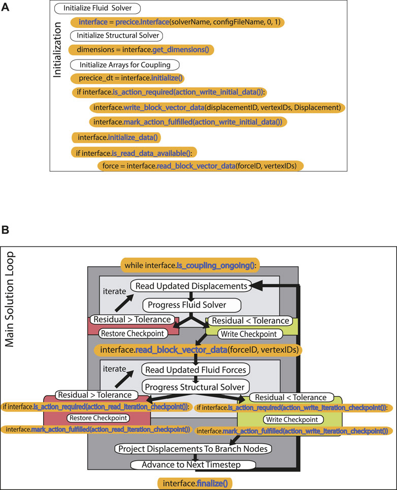
FIGURE 1. (A) preCICE commands utilized within FOAMySees initialization, (B) Diagram of preCICE subroutine calls within FOAMySees. This diagram is solely intended for informing about preCICE API function calls and where these calls are necessary, and is not indicative of the full coupling procedures for FOAMySees. For specific location of preCICE API function calls within FOAMySees, refer to the FOAMySees source code.
1.3 A new framework for open-source fluid-structure interaction—FOAMySees
The proposed program, “FOAMySees”, a portmanteau of “OpenFOAM’ and “OpenSees,” may be qualified as a coupling adapter for OpenSeesPy finite element models, structured within Python using preCICE’s Python language API bindings. While it is specialized to work with OpenFOAM, other CFD and FEM solvers could be coupled with OpenSeesPy via FOAMySees. In addition to this, the possibility exists within preCICE to couple multiple model models of similar types together. This would allow multiple OpenSeesPy models to be coupled to a single OpenFOAM model, allowing for simultaneous FSI of ensembles of structures. It would also allow users to couple another solver to the OpenFOAM/OpenSeesPy coupling, such as a shallow water solver to apply CFD inlet boundary conditions.
1.3.1 Theoretical background
The solution of complex turbulent fluid dynamics problems such as a tsunami inundation must be completed in three dimensions, due to the three-dimensional nature of turbulence. Since many structural finite element models utilize one-dimensional center-line and spring elements to represent three-dimensional structural components, additional steps must be taken to convert data such as rotations of structural nodes to displacements that accurately represent the rotation of the three-dimensional structural element modelled by elements along its center-line or mid-plane.
To account for this, volume must be generated in the coupled modelling space by extruding cross sectional shapes along the center-line elements. In FOAMySees, the cross sectional shape of the center-line elements is constructed by defining “data communication branch nodes” which exist solely outside the fluid solution and structural solution. “Data communication branch nodes” refer to the additional non-structural nodes which are utilized by FOAMySees and inaccessible to both solid and fluid solutions. These data communication branch nodes are radially centered relative to the FEM nodes and rotate rigidly about them.
Displacements of the finite element model are interpolated to these data communication branch nodes by the FEM node/branch node relationship described in Eq. 1 for each FEM-branch node group. The branch displacements from the FEM model at the completion of the current coupling timestep (tn), are utilized for progression of the finite volume domain displacement and evolution of the fluid model during the next coupling timestep (tn+1). In Eq. 1, BranchRotation refers to rigid-body rotation of branch nodes about FEM nodes using rotation matrices.
The mesh created by the collection of data communication branch nodes for all FEM nodes, the data communication mesh, is coupled by preCICE to the fluid mesh patch surfaces which represent the structure within the CFD model. Forces from the fluid model are conservatively applied to these branch nodes using radial basis function mapping from the CFD mesh patch nodes to the branch nodes. For all FEM nodes, the force vectors of the branch nodes associated with a given FEM node are summed to construct the force vector
Equilibrium at the ith node of a finite element model is defined as the balance of structural resistance and kinetic motion forces with external applied forces. For equilibrium at an interface between a structural dynamics model and an external dynamic force field to be satisfied, input and output work for a period of time must be equal or within satisfaction of a tolerance for residual in force between two sources. This means externally applied work for each node i must be roughly balanced by the product of the displacement of the structure with the resistance of the motion of the structure, as given in Eq. 3. For a single node within the structural dynamics model, acceleration in six degrees of freedom,
Unbalanced forces as defined by Eq. 4 are calculated by subtracting the internal dynamic resistance force components of the structural motion and deformed configuration at the current time from the applied forces, denoted as
These unbalanced forces are used at the end of the fluid model’s progression to the next coupling checkpoint at tn+1 to unbalanced forces between the beginning (tn) and end (tn+1) of the current coupling timestep. This relationship is summarized in Eq. 5. The unbalanced forces,
Depending on the coupling scheme, the solution process for each solver is completed serially or in parallel, and implicit or explicit; as such, these processes may occur in a different order than listed here, or may occur several times prior to progressing to the next timestep.
1.3.2 FOAMySees solution procedure
Prior to entering the solution procedure loop, FOAMySees initializes the OpenSeesPy model and FEM/branch node interpolator and sends FOAMySees data communication mesh (es) and initial values to preCICE for coupling to OpenFOAM. The following operations are then performed each timestep in sequence by FOAMySees components preCICE, OpenFOAM, and OpenSeesPy.
1. OpenFOAM: Reads data communication mesh displacements and integrates fluid dynamics model over time with mesh motion
2. preCICE: Calculates branch nodal forces at end of coupling timestep, and reads displacements and forces from both OpenFOAM and OpenSeesPy at end of OpenFOAM timestep to ensure residual convergence for implicit coupling schemes.
3. FOAMySees: Reads forces from preCICE, sums branch node forces from CFD analysis to FE model node locations, and calculates net nodal forces for OpenSeesPy timestep by subtracting nodal unbalanced forces and applies net nodal forces to OpenSeesPy nodes
4. OpenSeesPy: Integrates structural dynamics model over time and returns nodal displacements and unbalanced forces to FOAMySees
5. FOAMySees: Projects displacements from each FEM node to its associated branch nodes via rotation matrices
6. preCICE: Passes FOAMySees calculated data communication mesh displacement array to OpenFOAM for application of displacement boundary conditions during the next coupling timestep
A full description of the participants in the coupling process is shown in Figure 2. Software participants are listed along the left hand side of the figure. The order of operations for both FOAMySees initialization and timestepping is diagrammatically shown as an initialization phase, two interior loops, one solution loop for fluid solution internal residuals and one for those of the structural solution internal residuals, and one exterior loop per timestep, ensuring satisfaction of tolerances for residuals of coupling variables between participants.
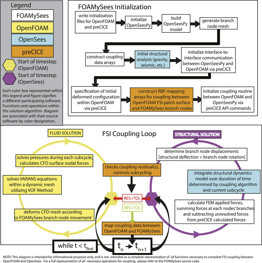
FIGURE 2. Coupling procedure for FOAMySees (abridged).
1.3.3 Surface-to-structure coupling using preCICE and FOAMySees
After initialization of the structural model along with optional branch nodes, the data communication mesh is passed to preCICE by FOAMySees. preCICE then calculates the interpolation mapping for passing of force and displacement data between OpenFOAM surface patch nodes and data communication mesh nodes. preCICE calculates forces to be passed to OpenSeesPy by integrating surface pressures over the regions of patch surface mapped to each branch node during each timestep as shown in Figures 3A, B. The process of calculating this mapping is routinely done by the use of RBF mapping, as depicted in Figures 4A, B, which is handled by configuring settings within the precice-config.xml file. Any OpenSees structural element formulation may be used within the FOAMySees framework; however, automeshing routines use non-linear displacement-based elements for beams and shells by default, and linear 8 node brick elements for solid meshes. An example of how each type of element connects to neighboring fluid surfaces is shown in Figures 5A–C.
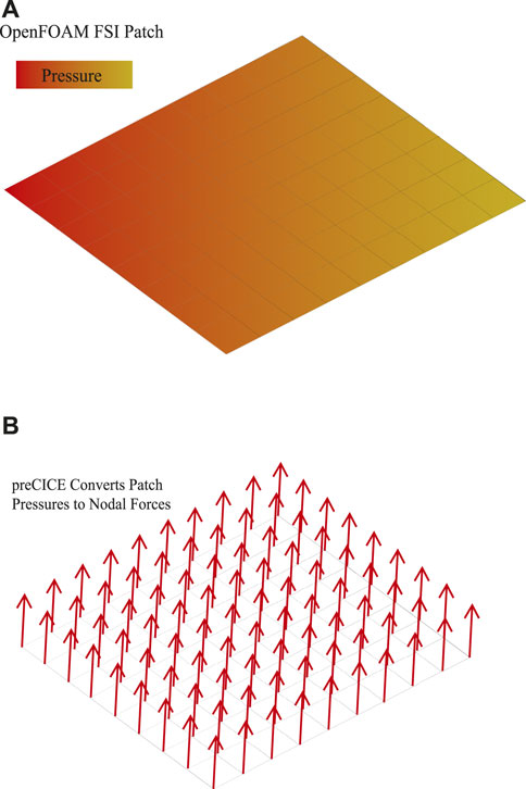
FIGURE 3. (A) OpenFOAM FSI Patch. (B) preCICE converts surface pressures along the FSI patch into nodal forces which may then be mapped to branch nodes.
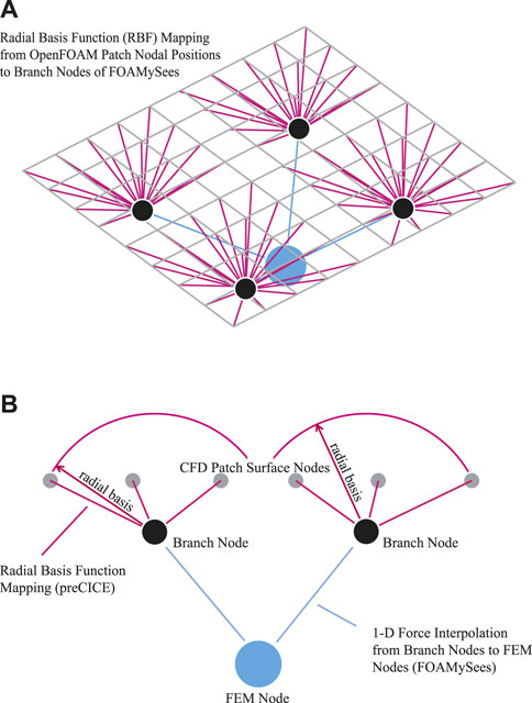
FIGURE 4. (A) Radial Basis Function (RBF) mapping is calculated between branch node positions and CFD patch surface nodes: Isometric View of RBF Mapping from OpenFOAM surfaces to branch nodes to FEM nodes, (B) Elevation View of RBF Mapping from OpenFOAM surfaces to branch nodes to FEM nodes.
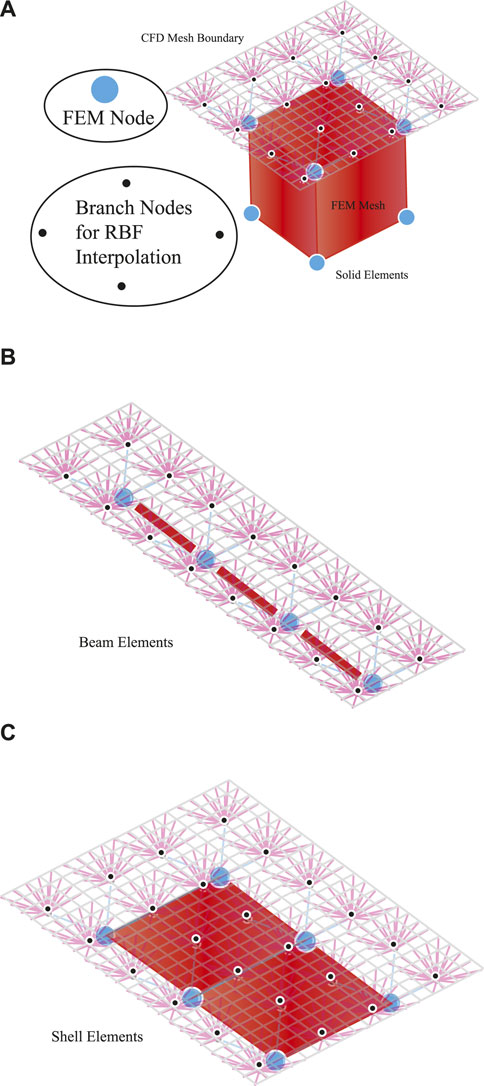
FIGURE 5. (A) Element Formulation Configuration W.R.T. Branch Nodes and FEM Nodes: FOAMySees utilizes branches as desired by the user—it is necessary for beam elements, recommended for shell elements, and unnecessary and improper for solid elements, as solid element meshes should be body-fitted: Solid elements, (B) Beam elements, (C) Shell elements.
1.3.4 Structural modeling and branch interpolation
During each timestep, after forces are mapped by preCICE via RBF to the FOAMySees branch nodes associated with each FEM structural node, branch node forces are summed and applied to the FEM nodes for evolution of the structural model during the next timestep or coupling iteration. The displacements of the FEM nodes are calculated using a user-specified numerical integration scheme at a maximum specified timestep, for a given number of sub-cycles. The branch node displacements are passed to preCICE at the end of the converged timestep. The displacements from FEM nodes are applied to the branch nodes associated with each FEM node via translation such that each of the n branch nodes per FEM node moves rigidly with the FEM node. The process of rigid-body rotation of branches about their FEM nodes is shown schematically in Figure 6. The branch nodes are then rotated rigidly about the FEM nodes via rotation matrix transformation, according to each nodes’ calculated local slope. Using the locations of these branch nodes at the previous timestep with respect to the deformed position of the nodes along the surface patch within the OpenFOAM model, preCICE interpolates the displacements from the branch nodes to the CFD patch surface nodes using the RBF mapping used previously. This process is shown schematically in Figure 7.
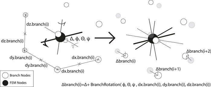
FIGURE 6. Illustration of rotation of branch nodes completed by FOAMySees.
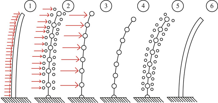
FIGURE 7. Conceptual evolution of branch node interpolation to FEM nodes and back. (1) Calculation of pressures (OpenFOAM). (2) Interpolation of surface pressures to branch nodal forces (preCICE). (3) 1D interpolation of branch forces for FEM nodes (FOAMySees). (4) Evolution of the structural model over one timestep (OpenSeesPy). (5) Interpolation of FEM nodal displacements and rotations to branch nodes (FOAMySees). (6) Interpolation of branch node displacements to CFD surface patch nodes (preCICE).
1.3.5 Time integration and time stepping
Time integration of the fluid model is completed with an Euler scheme. Stability of the fluid model requires a timestep small enough for satisfaction of Courant-Frederichs-Lewy cell fluid velocity criteria. The Newmark method with coefficients of γ and β valued 0.5 and 0.25 respectively was utilized for time integration of the structural model. As such, the maximum timestep increment for the structural dynamics simulation is contingent on structural material wave propagation timestep requirements and minimum element eigenvalue. A timestep sufficiently small enough to meet all stability criteria for the numerical integration routines of both structural and fluid solvers is chosen as the timestep for both the exchange of coupling data and individual solver time progression.
1.3.6 Coupling scheme
An explicit time progression scheme for coupling data is used in the following validation cases. Sub-cycling for CFD and FEM solvers is possible; alternatively, iterative techniques for interface manifold acceleration convergence such as Aitken Under-Relaxation and Iterative-Quasi-Newton Inverse-Least-Squares (IQN-ILS, Degroote and Vierendeels, 2011) may be implemented. These techniques are used to reduce analysis duration by increasing timestep sizes and improve stability of the coupling and are recommended over solver sub-cycling. In general, very small timesteps are recommended for first-order time integration schemes, as numerical damping may be large for explicitly coupled simulations with large timesteps.
1.3.7 Computational cost
The relative times for each computational component will vary depending on the mesh size of each participant and the boundary/initial conditions of each model. For a small scale structure modelled in FOAMySees with realistic materials (concrete, steel) and small displacements, comprised of 300 elastic shell elements and 304 non-linear frame elements with a fiber based section, resulting in 659 FEM nodes with 9,960 branch nodes coupled to 35,960 CFD patch surface nodes within an OpenFOAM model with 4,061,836 points and 3,917,848 cells, the mapping and structural analysis routines comprise about 16 percent of total computational time. For an OpenFOAM model with 4,061,836 points and 3,917,848 cells, 1 s of simulation time on 1 UW HYAK Klone HPC Node with 40 processors takes 1.57 h of computational time. For an equivalent FOAMySees model utilizing the CFD model previously mentioned on the same computational resources, the same simulation with FSI boundary conditions from a finite element model with 659 FEM nodes, 305 of which were coupled to the CFD patch surface utilizing between 8 and 48 branch nodes for each FEM node with a total of 9,960 branch nodes, takes only 20 percent longer than the equivalent CFD model with a computational time of 1.87 h.
1.4 FOAMySees program structure
1.4.1 FOAMySees object structure
The FOAMySees API is a collection of files which together form the object OpenSeesPyInstance and the main coupling solution loop for fluid-structure. The coupled solution is initialized by calling the Python routine within Solid1Solver.py, which creates an OpenSeesPyInstance object. This object contains the OpenSeesPy model and metadata about the model, as well as arrays through which data is transferred to and from OpenSeesPy at each timestep. In addition to this, there are sub-routines which write and read checkpoints (OpenSeesPyInstance.stepForward), iterate for a solution (OpenSeesPyInstance.iterate), and rotate branch nodes about their associated FEM nodes for branch mesh updates (OpenSeesPyInstance.RotateTreeBranch).
FOAMySees is structured in such a way that the definition of component OpenFOAM and OpenSeesPy models for coupled FSI analysis does not vary greatly from the definition of individual structural models with OpenSeesPy or individual fluid models within OpenFOAM. Users may define their OpenSeesPy model as usual within the file Solid/buildOpenSeesModelInThisFile.py. This model is coupled with the fluid model contained with the Fluid/subfolder. Model settings such as time-stepping settings and interface coupling options are controlled via files contained within the Solid/subfolder, particularly Solid/timeSettings.py and Solid/geometrySettings.py. Preliminary analysis such as gravity loading with dynamic relaxation or seismic non-linear time history analysis may be defined as usual within the file FOAMySees/prelimAnalysis.py. This sub-routine is called before the fluid-structure interaction analysis loop, and the final state of the OpenSeesPy model at the end of the preliminary analysis is utilized as the initial state within the FSI model, including damage represented by material model variable time-histories, initial stresses and deflections.
1.4.2 Coupled analysis file structure
FOAMySees maintains a standard OpenFOAM file structure for a CFD model with dynamic mesh capabilities. A few additional files besides the those required for a standard multiphase OpenFOAM simulation necessary for initializing connections to coupling routines in preCICE are also included. These files include preciceDict, which is stored within the OpenFOAM case subfolder Fluid/system/, and precice-config.xml. The preCICE coupling adapter for OpenFOAM, which reads and writes forces and displacements, is called via the function object preciceAdapterFunctionObject which is defined in the file Fluid/system/controlDict. This function object is available for use within OpenFOAM only after installing preCICE and the associated OpenFOAM adapter (available at https://github.com/precice/openfoam-adapter. Note: for incompressible multi-phase OpenFOAM solvers, a modified adapter found at https://github.com/moaxm/openfoam-adapter is recommended for proper calculation of interface forces, and was utilized in this study). Coupling settings are managed and defined in the file precice-config.xml, which includes the coupling timestep data and partners, residual convergence tolerances, coupling acceleration techniques (Aitken, Broyden, IQN-ILS, IQN-IMVJ), and data exchange mechanisms for coupling (sockets vs. mpi).
Initialization of coupling partners is completed by running a program batch script in bash on the Linux operating system. This script performs all necessary OpenFOAM pre-processing steps, decomposes the case amongst desired computational processors and nodes, and initializes the parallelized OpenFOAM case for coupling with the OpenSeesPy model. It then performs all pre-processing for the OpenSeesPy model, and initializes the OpenSeesPy model and FOAMySees interface for coupling with the existing OpenFOAM model. At this point, a preliminary OpenSeesPy analysis may be performed including any combination of gravity loading, preloading of structure with dead loads, and earthquake loading prior to initialization of the fluid-structure interaction simulation. The coupling between OpenSeesPy and OpenFOAM is controlled via the FOAMySees python class instance initialized at the beginning of the coupled analysis. This object also controls OpenSees configuration, model progression in time, and communication of displacement and force vectors.
1.5 Test cases
1.5.1 Hydrostatic Force FSI case
A quasi-static FSI case was developed using a beam with fixed-fixed end conditions. The domain was 10 m in length, 1 m in height, and 0.1 m in thickness. Water was initialized at a depth of 0.5 m, and the modulus of elasticity of the elastic beam was varied to verify expected forces are applied from OpenFOAM to the structural nodes within OpenSeesPy, and that correct displacements are returned from OpenSeesPy to OpenFOAM. The modulus of elasticity of the beam was deemed the least consequential variable to change with respect to other variables. Varying modulus of elasticity between cases allows for a consistent domain size, VOF phase-fraction, beam mass, beam element size, cell size, and beam cross section dimensions while providing a linear change in displacement with respect to the elastic modulus. A diagram of the case showing reduction of the fluid loading to a distributed load is shown in Figure 8A.
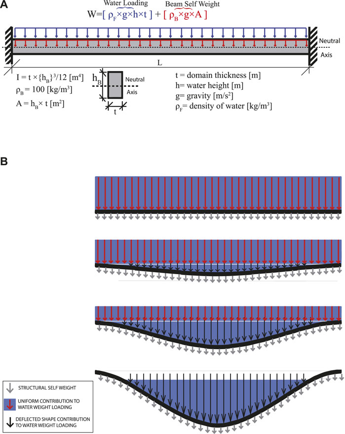
FIGURE 8. (A) Beam with properties E, I, L, A, ρB, within a domain t m wide, topped with water h m deep, under uniform gravity loading g, (B) Change of loading contribution with displacement of beams under shifting water.
The expected center span displacement for a fixed-fixed Euler-Bernoulli beam under a uniform distributed load is WL4/384EI. With an equivalent distributed load of 490.5 N/m (0.5 m × 0.1 m × 9.81 m/s2 × 1000 kg/m3), a length of 10 m, a moment of inertia of 100 m4, and with elastic modulus of 5E+09 Pa, the center span displacement is 2.55469E-08 m. Center span displacements for beams with softer moduluses of elasticity are shown in Table 3, along with the calculated center span displacement for the beam from an FSI model with identical properties.
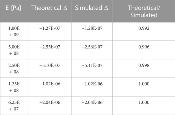
TABLE 3. Fixed Beam: Predicted [WL4/384EI] vs. Simulated Displacements, W = 490.5 [N/m], L = 10 [m], I = 100 [m4].
1.5.2 Fixed-end frame under shifting hydrodynamic gravity loading
The same domain geometry as described in the Hydrostatic Force FSI Test Case section was utilized to examine the effect of large displacements upon the shifting of water sitting atop fixed-end frames. Frames for this test case possessed a moment of inertia of 8.33E-3 m4, a length of 10 m, a cross sectional area of 0.1 m2, and elastic modulus ranging from 1E + 08 Pa to 1E + 06 Pa. These properties were chosen to amplify the effects of fluid pooling upon the deflection imparted against frame elements. As the deflection increases, the loading distribution becomes more concentrated near the beam mid-span, as fluid redistributes itself naturally to find a free surface that results in equilibrium between the internal structural forces and external fluid pressure. An illustration of this behavior is shown in Figure 8B. Since the geometry, sections, materials, and loading chosen in this example result in large displacements, multiple phenomena contribute to the behavior of the frame elements, including frame rotational stiffening effects due to tension. OpenSees-only simulations were run with uniform distributed loads due to the fluid pressure in its initial configuration to assess the affects of axial load (i.e., tension stiffening) in this example case. The effect of axial force upon rotational stiffening is evident in Figure 9A—all calculated deflection curves, most notably the curve with “static” loading, tend to decrease in magnitude beyond a deflection to length ratio of 1:100 for this given case. For sections with different ratios of moment of inertia to area, this behavioral inflection point due to frame stiffening effects will also differ.
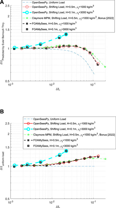
FIGURE 9. (A) FOAMySees solution: Center span displacement of beams under shifting water loading, (B) normalized by uniform Load deflection: FOAMySees solution for center span displacement of beams under shifting water loading.
As the deflection to length ratio increases, so does the effect of the pooling of the water at the center of the frame upon the expected maximum deflection. A prediction loading function for determining quasi-static loading of beams under pooling water at various deflections was developed, as calculated by Eq. 6. These loads were applied dynamically to frame elements in OpenSeesPy identical to those which were used in the FSI simulations, in efforts to provide an independent benchmark against which FOAMySees calculated loads and results could be compared. The prediction loading function estimates the fluid elevation required above a particular deformed frame shape to achieve quasi-static equilibrium between the beam in its deformed shape and the “pooled” water sitting atop the beam. This calculation is completed after every timestep within a dynamic analysis to account for the current deformed shape.
where
Results from this study are shown via curves termed “OpenSeesPy, Shifting Load”, shown in Figures 9A, B. Figure 9B is simply a normalized Figure 9A—each curve was normalized by the “OpenSeesPy, Uniform Load” results calculated in OpenSeesPy to isolate the effects of load redistribution due to fluid pooling upon the frame near the center of its span. A fluid with a higher density and a lower still water level was utilized to both simulate a case within FOAMySees and compare with the quasi-static load shape calculation described previously in this section. This case is labeled as “OpenSeesPy, Shifting Load, H = 0.1 m, ρf = 3000 kg/m3” in Figure 9B. Results are compared with a solution provided by Bonus, 2023, which utilized Material Point Method (MPM) for simulation of both fluid and structure solutions. Figures 9A, B both show strong agreement with the solutions provided by Bonus—slight variations between both solutions exist due to the presence of structural shear deformation effects within the MPM solution for the beam.
To demonstrate the dynamic nature of the FOAMySees code, snapshots were selected from a case within this example, particularly the case with the largest displacements and therefore the largest displacement to length ratio. In Figure 10A, four points in time during the simulation are marked as points A, B, C, and D respectively. In sub-figures Figures 10B–E, free surface elevation snapshots are displayed, showing the redistribution of water along the length of the frame and the settlement of the frame into a loading configuration that resulted in much larger deflections than what would occur for a uniform distributed load case.
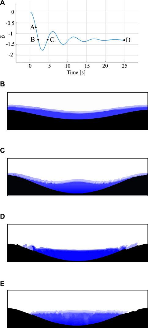
FIGURE 10. (A) FOAMySees solution: Center span displacement of E = 1E6 beam under shifting water loading, (B) point A (1.5 s), (C) point B (2.2 s), (D) point C (4.7 s), (E) point D (25 s).
1.5.3 Laminar multiphase hydrodynamic impact
Winter, (2019) is an analytical FSI case comprised of a 2D multi-phase fluid dam break within a tank with initial conditions as shown in Figure 11A which impinges upon a flexible flap affixed to the floor of the tank. The fluid properties correspond to water and air, so that ρ1 = 1.0 g/cm3 (1000 kg/m3) and μ1 = 0.01 g/s/cm while ρ2 = 0.001 g/cm3 (1 kg/m3) and μ2 = 0.0001 g/s/cm.The structure is elastic, 1.2 cm wide by 8 cm tall, with density ρ0 = 2.5 g/cm3 (2500 kg/m3), Young’s modulus E = 107 g/cm/s2 (1 MPa) and Poisson’s ratio = 0.3.
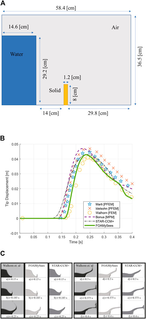
FIGURE 11. (A) Laminar multiphase hydrodynamic impact validation case setup, (B) Walhorn et al. Validation case: FOAMySees comparison to other solution, (C) Walhorn et al. fluid free surface comparison: left, grey background-Walhorn et al. Center-FOAMySees. Right, white background- STAR-CCM+.
Results show strong correlation between the coupled FEM—CFD solution (FOAMySees) and historical results for the same geometry and initial conditions modelled with finite elements entirely or using the particle finite element method. The case was modelled in STAR-CCM + using 8-node bricks with non-linear geometry model enabled to compare results with commercial software. The lateral displacement time history for the top left corner of the flap is shown in Figure 11B. Results from Marti et al. (2006); Idelsohn et al. (2008); Bonus, 2023 are shown as well, demonstrating large variability in the post-bore-impact phase from the dam break amongst various codes. Walhorn utilized a finite element solution for both structural and fluid dynamics. Idelson and Marti utilized particle finite element methods (PFEM) for the fluid solution coupled with finite elements for the structure. Bonus utilized Material Point Method (MPM) for simulation of both fluid and structure components of the solution. STAR-CCM + utilized CFD for solution of the fluid motion and FEM for motion of the flexible flap. Free surface comparisons to results obtained from Walhorn et al. are shown in Figure 11C. Snapshots from various points along the solution progression show good agreement with the original solution provided by Walhorn.
1.5.4 Post-earthquake laminar multiphase hydrodynamic impact
Identical domain geometry, fluid properties, and fluid initial conditions as described in the Laminar Multiphase Hydrodynamic Impact section were utilized to demonstrate the multi-hazard analysis capabilities of FOAMySees. A fiber section with “non-linearBeamColumn” formulation frame finite elements were used to represent the flap. Material properties of the flap were modified to allow for material yielding and hardening. The flap material chosen was the OpenSeesPy Uniaxial Hardening material, with Young’s modulus E = 107 g/cm/s2 (1 MPa), Yield Stress = 106 g/cm/s2 (100 Kpa), and hardening parameters Hiso = 0.15 and Hkin = 0.25.
The analysis case was run twice; first without a preliminary earthquake analysis to establish a baseline displacement time history with a non-linear material with which to compare, and again with a ground motion excitation preceding the fluid-structure interaction analysis. A plot of the horizontal acceleration over time and flap tip response to the excitation are shown in Figures 12A, B respectively. Ground motion was stopped after 3 s and free vibration of the flap was allowed until 15 s. Numerical damping was utilized in the seismic analysis through the means of changing the Newmark integration coefficients to γ = 0.66 and β = 0.33. The final deformed shape of the structure at the time of termination of the preliminary seismic analysis resulting in a flap tip displacement of −0.0045 m was utilized as the initial configuration of the structure within the fluid-structure analysis. Both cases are plotted alongside the original FOAMySees solution for the Walhorn validation case in Figure 12C. The results show that in this case both material non-linearity and material history variables play a role in the flap tip displacement response to impact from the breaking dam.
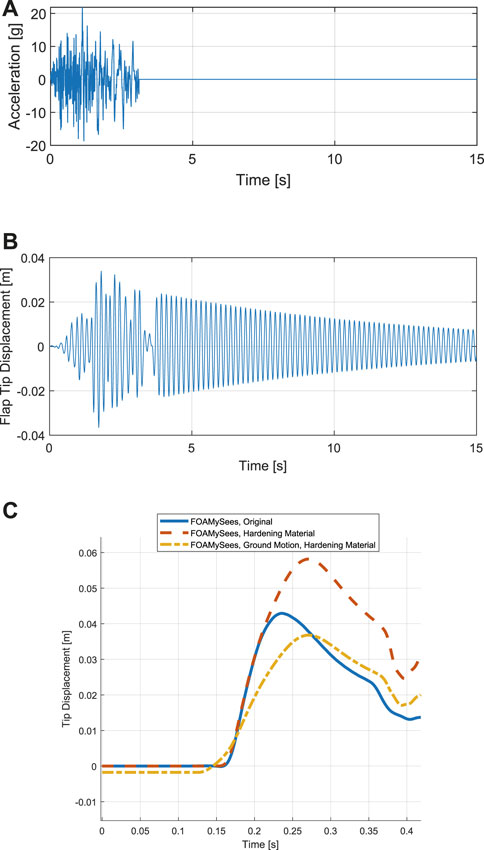
FIGURE 12. (A) ground motion utilized in preliminary seismic analysis (B) flap tip displacement resulting from base ground motion excitation prior to fluid-structure analysis, (C) comparison between FOAMySees Laminar hydrodynamic impact solutions—Demonstration of material hardening effects due to preliminary seismic loading upon flap tip displacement.
1.5.5 Three dimensional structure under turbulent breaking solitary wave impingement with real structural sections and materials
In order to evaluate the efficacy of the force and displacement mapping routines for complex three dimensional geometries, a 1:5 full scale structure studied experimentally by Sullivan (2021) within the Large Wave Flume at Oregon State University O.H. Hinsdale Wave Research Laboratory was modelled in OpenFOAM and FOAMySees.
1.5.5.1 Structural model description
The structure was 1.016 m by 1.016 m in plan from column center to column center, comprised of steel frame elements, steel gusset plates, and concrete filled steel tubes. HSS2 × 2 × 1/8 elements were framed horizontally between columns with their center-line at heights of 1.3208 m, 1.8288 m, and 2.3368 m HSS1.5 × 1.5 × 1/4 elements were utilized for chevron bracing from 1.3208 m to 1.8288 m along all four sides of the structure. Panels spanned between HSS2 × 2 elements forming diaphragms within the structural plan footprint. For exact material properties of the experimental specimen and exact structural dimensions, see Sullivan (2021). Uni-axial material properties for structural steel (“Steel02” model, with a yield stress of 344.75 MPa, initial elastic tangent of 200 GPa, strain-hardening ratio of 0.1, and isotropic hardening parameters of a1, a2, and a3 of 18.0, 0.925, and 0.15, respectively) and concrete (“Concrete02” model, with concrete compressive strength at 28 days of −49.64 MPa, concrete strain at maximum strength of −0.00326, concrete crushing strength of −9.93 MPa, concrete strain at crushing strength of −0.01631, ratio between unloading slope and initial slope of 0.1, tensile strength of 4.39 MPa, and tension softening stiffness of 2 GPa) respectively were chosen for modelling materials within OpenSeePy, and gusset plates were not modelled. EqualDOF commands were utilized for connection of structural elements of different formulations within OpenSeesPy. The structure was fixed at its base. Fiber sections with elastic uniaxial materials and 64 fibers each were utilized to represent the composite sections of the columns, which were standard 10.16 cm (4 in) steel pipes with 1.27 cm (1/2 in) thick walls filled with concrete. Elastic beam sections were utilized for the HSS components of the frame. Elastic MITC4 shell elements were utilized for the modelling of the panels spanning across each story, which were given a thickness of 12.7 mm (1/2 in) and material properties of elastic steel. The model was given Rayleigh damping in OpenSeesPy with a value of 7.5% from the frequency of the first structural mode (f1) to five times that frequency (5f1) with Rayleigh mass coefficients of αmass = 0.0 and Rayleigh stiffness coefficients of
1.5.5.2 Fluid model
The Large Wave Flume is 104.0 m long, 3.7 m wide, and 4.6 m deep, with waves generated by a piston-type wavemaker on the upstream end of the flume. The model was initialized with a still water level (SWL) of 2.0 m, and the structural model and CFD patch surfaces were positioned approximately 40.77 m from the neutral position of the wave maker. A paddle-generated wave with a maximum crest height of 1.45 m and a celerity (the velocity with which a wave advances) of 5.82 m/s within a still water level of 2 m was sent down the flume toward the structure. As the Oregon State University O.H. Hinsdale Wave Research Laboratory Large Wave Flume CFD model with paddle driven waves utilized in this study has been used previously and its information is available in literature, details are omitted here for brevity. See Lewis et al. (2022) for detailed information about the flume geometry and bathymetry, initial conditions of the water within the flume, location of the specimen in the flume, paddle driven wave properties, validation of wave height and velocity with experimental results, CFD boundary conditions utilized, turbulence model properties, and detailed OpenFOAM modelling procedures. The geometry of the structure (elevated structure rather than a concrete shear core) and mesh motion (pointDisplacement) boundary conditions were the only components changed in OpenFOAM between the model utilized in the previously cited study and the model utilized presently. For detailed information about OpenFOAM modelling procedures utilized for paddle generated waves and recommendations for CFD modelling of complex structures, see Winter (2019).
1.5.5.3 Branch meshes
Two branch meshes of roughly 25,000 nodes each were utilized in this example. The first branch mesh was utilized for displacement transfer from FOAMySees to OpenFOAM, and consisted of a point cloud identical to that of the CFD surface patch nodal locations. The second branch mesh was utilized for force transfer from OpenFOAM to FOAMySees and consisted of a point cloud identical to that of the CFD patch surface face centers. The purpose of this was to ensure direct mapping of forces from their calculated locations (CFD patch surface face centers) to branch nodes with FOAMySees, and direct mapping of FOAMySees calculated branch displacements to the CFD surface patch nodes to demonstrate scalability of FOAMySees without the need for coupling mesh convergence studies for this example. FEM node to branch node relationships were generated automatically by means of a clustering algorithm, namely, the KDTree functions within the scipy Python package. The OpenFOAM patch surface node locations were loaded into FOAMySees as a point cloud, and were each clustered to the OpenSeesPy FEM node which was closest in absolute distance. This operation was also completed with the CFD patch surface face centers providing two branch groups for each FEM node, with each controlling either displacement or force transfer to preCICE for application to the OpenFOAM model. A select number of FEM nodes were chosen for coupling to CFD patch surfaces as the full geometry of the structure was not represented in OpenFOAM. The CFD patch surface utilized in this analysis with the OpenSeesPy model used in FOAMySees overlaid is shown in Figure 13A and the displacement branch groupings utilized are shown in Figure 13B.
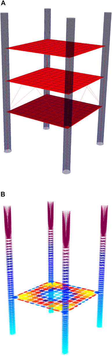
FIGURE 13. (A) OpenSeesPy model overlaid by OpenFOAM CFD patch surface, (B) Branch clusters utilized in analysis.
1.5.5.4 Computational cost
The model was run for 4 s of simulation time at a timestep of 0.0005 s on 1 UW HYAK Klone HPC Node with 40 processors for a total computational time of 14 h. In comparison to a geometrically similar model utilized for benchmarking computational cost with respect to an equivalent CFD model (9,960 branch nodes coupled to 35,960 CFD patch surface nodes) the first second of the simulation with the present model (50,000 branch nodes coupled to 50,000 CFD patch nodes) took roughly 3.5 h, which is nearly twice the computational time of the model described in Section 1.3.7 with nearly identical node and cell counts within the CFD models compared (4,034,512 points and 3,894,298 cells versus 4,061,836 points and 3,917,848 cells). For more information, see Section 1.3.7.
1.5.5.5 Results
Mesh motion of OpenSeesPy, the FOAMySees displacement branch mesh, and OpenFOAM surface patches along with fluid free surface (isosurface at α = 0.5) overlaid for selected times of the simulation are shown in Figures 14A–C. In Figure 14D a time history of the displacement of the top left corner on the upstream face of the structure in OpenSeesPy and its associated location in OpenFOAM are plotted alongside each other to demonstrate proper transfer of displacement during the simulation. To demonstrate proper transfer of force between coupled models, the forces applied to the branch nodes within FOAMySees were output and summed for comparison with the force calculated within OpenFOAM via functionObjects. The streamwise force time histories for both OpenFOAM and FOAMySees are shown along with experimentally measured forces from Sullivan (2021) for the duration of wave impingement in Figure 14E, and errors for force and impulse transfer across interfaces is shown in Figure 14F.
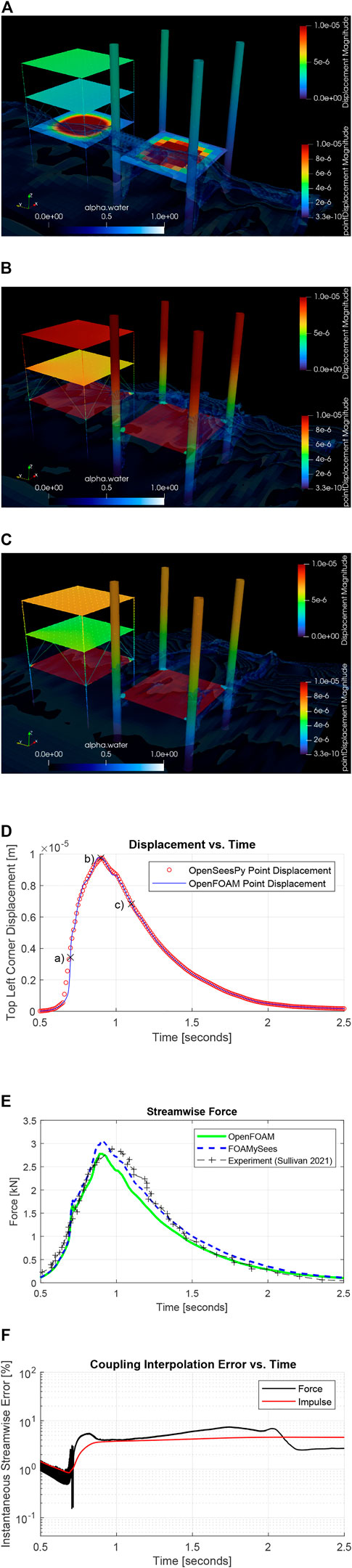
FIGURE 14. (Continued).
2 Conclusion
The presented work offers a highly scalable, versatile, open-source methodology for numerical simulation of non-linear fluid-structure interaction. By allowing for geometric discrepancies between structural and fluid solvers and compensating for this through the use of branch node data communication meshes, high-resolution reduced order center-line element and shell element comprised finite element models may be utilized to simulate the response of structures to fluid loading in three dimensions. This methodology has been validated through several static analysis cases, one high energy dam break case involving a flexible rubber flap placed within the path of flow, and a medium-scale case representing a 1:5 scale structure comprised of steel and concrete subject to breaking solitary wave impingement tested previously at Oregon State University. Additionally, the high energy dam break case was run with seismic excitation preceding the fluid-structure interaction simulation to demonstrate damage state coherence between termination of the preliminary structural analysis subroutines and the initial state of the fluid-structure analysis. More testing of the software and coupling methodology is necessary to determine rate of convergence of solution, memory usage, limits of the branch node data communication mesh method, and timestep stability regimes of the presented coupled solution technique with respect to limiting factors within both the finite element and computational fluid dynamics methodologies. This includes investigating feasibility and advantages of utilizing iterative techniques for interface manifold acceleration convergence such as Aitken Under-Relaxation and Iterative-Quasi-Newton Inverse-Least-Squares (IQN-ILS). Furthermore, more work must be done to validate the solution technique offered by the proposed API with experimental studies conducted at large scales. A detailed investigation of how turbulence modelling affects results was not considered in the present study, thus more research must be completed to assess the accuracy of results provided by FOAMySees when utilizing OpenFOAM fluid solvers which incorporate turbulence modelling.
Data availability statement
The raw data supporting the conclusion of this article will be made available by the authors, without undue reservation.
Author contributions
Conceptualization: NL, AW, MM, DL, ME, and PA. Visualization, Methodology, and Software: NL. Data Curation, Validation, and Investigation: NL, JB, and AW. Resources: NL, AW, JB, MM, PA, and DL. Writing—Original Draft: NL and AW. Funding acquisition, Project administration, Supervision, Writing—Review Editing: MM, DL, ME, and PA. (Nomenclature according to CRediT guidelines—Contributor Roles Taxonomy).
Funding
The authors thank the NHERI Computational Modeling and Simulation Center (SimCenter), National Science Foundation (NSF) and Joy Pauschke (program manager) for their financial support of this project through Grants CMMI-1726326 and CMMI-1933184.
Acknowledgments
This work was facilitated through the use of advanced computational, storage, and networking infrastructure provided by the Hyak supercomputer system, supported in part by the University of Washington eScience Institute.
Conflict of interest
The authors declare that the research was conducted in the absence of any commercial or financial relationships that could be construed as a potential conflict of interest.
Publisher’s note
All claims expressed in this article are solely those of the authors and do not necessarily represent those of their affiliated organizations, or those of the publisher, the editors and the reviewers. Any product that may be evaluated in this article, or claim that may be made by its manufacturer, is not guaranteed or endorsed by the publisher.
References
Bonus, J. (2023). Evaluation of Fluid-Driven Debris Impacts Using a Multi-GPU Material Point Method. Ph.D. Thesis. Seattle, WA: UW Digital Libraries.
Bungartz, H.-J., Lindner, F., Gatzhammer, B., Mehl, M., Scheufele, K., Shukaev, A., et al. (2016). Precice – a fully parallel library for multi-physics surface coupling. Comput. Fluids 141, 250, doi:10.1016/j.compfluid.2016.04.003
Croquer, S., Diaz-Carrasco, P., Poncet, S., Lacey, J., and Nistor, I. (2022). Numerical benchmark for modelling wave impacts against vertical walls using openfoam. Proceedings of the 39th IAHR World Congress From Snow to Sea, January 2022, Spain, IAHR, dodoi:10.3850/IAHR-39WC2521716X2022201
Degroote, J., and Vierendeels, J. (2011). “A partitioned quasi-Newton solution technique for fluid-structure interaction problems using a coarsened grid to accelerate the convergence of the coupling iterations,” in Computational methods for coupled problems in science and engineering IV. Editors M. Papadrakakis, E. Oñate, and B. Schrefler (Oslo, Norway: European Community on Computational Methods in Applied Sciences ECCOMAS), 100–111.
Douglas, S., and Nistor, I. (2014). On the effect of bed condition on the development of tsunami-induced loading on structures using openfoam. Nat. Hazards 76, 1335, doi:10.1007/s11069-014-1552-2
Douglas, S., Nistor, I., and St-Germain, P. (2015). “3-d multi-phase numerical modelling of tsunami-induced hydrodynamic loading on nearshore structures,” in IAHR World Congress 2015At: The Hague, Netherlands, July 2015 (IAHR).
Elsheikh, N., Azimi, A. H., Nistor, I., and Mohammadian, A. (2022a). Tsunami-induced bores propagating over a canal, part ii: Numerical experiments using the standard k-ɛ turbulence model. Fluids 7, 214. doi:10.3390/fluids7070214
Elsheikh, N., Nistor, I., Azimi, A. H., and Mohammadian, A. (2022b). Tsunami-induced bore propagating over a canal-part 1: Laboratory experiments and numerical validation. Fluids 7, 213. doi:10.3390/fluids7070213
Hirt, C., and Nichols, B. (1981). Volume of fluid (vof) method for the dynamics of free boundaries. J. Comput. Phys. 39, 201. doi:10.1016/0021-9991(81)90145-5
Idelsohn, S., Marti, J., Limache, A., and Oñate, E. (2008). Unified Lagrangian formulation for elastic solids and incompressible fluids: Application to fluid-structure interaction problems via the pfem. Comput. Methods Appl. Mech. Eng. 197, 1762. doi:10.1016/j.cma.2007.06.004
Jasak, H. (2009). Dynamic mesh handling in openfoam, 47th AIAA Aerospace Sciences Meeting including The New Horizons Forum and Aerospace Exposition, Orlando, Florida, 05 January–08 January, 2009. doi:10.2514/6.2009-341
Jasak, H., and Tukovic, Z. (2006). Automatic mesh motion for the unstructured Finite Volume Method. Trans. FAMENA 30, 1–20.
Lewis, N. S., Lehman, D. E., Motley, M. R., Arduino, P., Roeder, C. W., Pyke, C. N., et al. (2022). Integrated study of existing tsunami design standards. J. Struct. Eng. 148, 04022200. doi:10.1061/(ASCE)ST.1943-541X.0003506
Liu, S., Nistor, I., Mohammadian, A., and Azimi, A. H. (2022). Experimental and numerical investigation of beach slope effects on the hydrodynamic loading of tsunami-like surges on a vertical wall. J. Mar. Sci. Eng. 10, 1580. doi:10.3390/jmse10111580
Marti, J. M., Idelsohn, S., Limache, A., Calvo, N., and D’Elía, J. (2006). A fully coupled particle method for quasi-incompressible fluid-hypoelastic structure interactions, ENIEF 2006 XV Congreso sobre Métodos Numéricos y sus Aplicaciones, Santa Fe, Fluid Structure Interaction Volume XXV (9).
McKenna, F., Scott, M. H., and Fenves, G. L. (2010). Nonlinear finite-element analysis software architecture using object composition. J. Comput. Civ. Eng. 24, 95. doi:10.1061/(asce)cp.1943-5487.0000002
Motley, M. R., Wong, H. K., Qin, X., Winter, A. O., and Eberhard, M. O. (2016). Tsunami-induced forces on skewed bridges. J. Waterw. Port, Coast. Ocean Eng. 142, 1. doi:10.1061/(ASCE)WW.1943-5460.0000328
Qin, X. (2019). Efficient tsunami simulation at local and global scales. Ph.D. Thesis, Seattle, WA: UW Digital Libraries. Available at: http://hdl.handle.net/1773/44758.
Qin, X., Motley, M. R., and Marafi, N. A. (2018). Three-dimensional modeling of tsunami forces on coastal communities. Coast. Eng. 140, 43. doi:10.1016/j.coastaleng.2018.06.008
Sarjamee, S., Nistor, I., and Mohammadian, A. (2017a). Large eddy simulation of extreme hydrodynamic forces on structures with mitigation walls using openfoam. Nat. Hazards 85, 1689. doi:10.1007/s11069-016-2658-5
Sarjamee, S., Nistor, I., and Mohammadian, A. (2017b). Numerical investigation of the influence of extreme hydrodynamic forces on the geometry of structures using openfoam, Nat. Hazards 87, 213. doi:10.1007/s11069-017-2760-3
Sullivan, K. P. (2021). Testing of a new composite framing system for vertical evacuation structures. M.S. Thesis. Seattle, WA: UW Digital Libraries. Available at: http://hdl.handle.net/1773/47026.
Weller, H. G., Tabor, G., Jasak, H., and Fureby, C. (1998). A tensorial approach to computational continuum mechanics using object-oriented techniques. Comput. Phys. 12, 620. doi:10.1063/1.168744
Winter, A. (2019). Effects of flow shielding and channeling on tsunami-induced loading of coastal structures. Ph.D. thesis. Seattle, WA: UW Digital Libraries. Available at: http://hdl.handle.net/1773/45151.
Wong, H. K. W. (2015). Three-dimensional effects of tsunami impact on bridges, Available at: http://hdl.handle.net/1773/33666.
Keywords: fluid-structure interaction, computational fluid dynamics, finite element analysis, non-linear structural analysis, natural hazards, simulation
Citation: Lewis NS, Winter AO, Bonus J, Motley MR, Eberhard MO, Arduino P and Lehman DE (2023) Open-source simulation of strongly-coupled fluid-structure interaction between non-conformal interfaces. Front. Built Environ. 9:1120518. doi: 10.3389/fbuil.2023.1120518
Received: 10 December 2022; Accepted: 28 February 2023;
Published: 22 March 2023.
Edited by:
Julio Alfonso Ramirez, Purdue University, United StatesReviewed by:
Hoang Nam Phan, Roma Tre University, ItalyAndrew Brian Kennedy, University of Notre Dame, United States
Copyright © 2023 Lewis, Winter, Bonus, Motley, Eberhard, Arduino and Lehman. This is an open-access article distributed under the terms of the Creative Commons Attribution License (CC BY). The use, distribution or reproduction in other forums is permitted, provided the original author(s) and the copyright owner(s) are credited and that the original publication in this journal is cited, in accordance with accepted academic practice. No use, distribution or reproduction is permitted which does not comply with these terms.
*Correspondence: Nicolette S. Lewis, nsaoirse@uw.edu