Design code review on seismic demand and base detailing criteria: an application to wine tanks in Marlborough
 Marco Frezzati
 Giuseppe Loporcaro
 Nicola Buratti
 Alessandro Palermo
 Adam Walker3
- 1Department of Civil Engineering, University of Bologna, Bologna, Italy
- 2Department of Civil and Natural Resources Engineering, University of Canterbury, Christchurch, New Zealand
- 3Kotahi Engineering Studio, Lyttelton, New Zealand
Marlborough is the largest wine-growing region in New Zealand. The seismic events of Lake Grassmere 2013 and Kaikōura 2016 caused severe business disruption to the wineries due to the poor performance of wine storage tanks and connected non-structural components. The damage recorded raised two main discussions concerning the NZSEE 2009 guidelines for seismic design of liquid storage tanks. The first is related to the appropriateness of the determination of the importance level to adopt for the design of tanks. In fact, importance level 1 (IL1) (structures presenting a low degree of hazard to life and other property) was adopted for most wine tanks, and therefore, the horizontal forces designed were extremely low. Adopting importance level 2 (IL2) (normal structures) would have increased the overall seismic demand to design them for and therefore limited their structural damage but potentially increased the structural cost. The second concerns the design detailing of the critical connections. In fact, the current guidelines/standards lack provisions. The authors compare the NZSEE 2009 guideline with Eurocode 8 (EC8) and API 650 through the design of six tanks with typical dimensions used in the New Zealand wine industry. Results show that assigning importance level 1 results in seismic design demand similar to EC8 and API 650, thereby showing that other countries have a similar approach to New Zealand. A further comparative analysis also highlighted that connection detailing design including the hierarchy of strength is totally missing in all three standards/guidelines, which lacks information.
1 Introduction
Wine tanks are the lifelines and critical structures of wineries (Zhao and Zhou, 2018), one of the most strategic industries in New Zealand and many other wine-producing countries (New Zealand Wine Growers Inc., 2022). The failure of wine tanks leads to significant economic losses as they are used for the fermentation and storage of wine. Wine tanks are sealed, ground-supported liquid storage systems that have a vertical cylindrical shape and are made of 2–6 mm stainless steel walls (Zhao and Zhou, 2018). The use of stainless steel brings some advantages, such as ease of cleaning, chemical inertness, appearance, and better control of the wine fermentation (Colombo and Almazán, 2017). Wine tanks are classified as slender structures since the height (H)-to-radius (R) ratios range between 3 and 5 (Au et al., 2015; Hosseini and Beskhyroun, 2023).
While liquid-storage structures are known as tanks, silos are structures used to store solid-granular materials such as wheat, rice, and corn (Khalil et al., 2022). There are some similarities between tanks and silos, such as the cylindrical shape and the use of steel, stainless steel, and reinforced concrete. The seismic response of tanks and silos is governed by the slenderness of the structure. Tanks and silos have different dynamic responses due to the nature of the granular solid materials. The dynamic response of silos is affected by the type and properties of the granular material (e.g., bulk unit weight, internal friction angle, and grain–wall friction) (Khalil et al., 2022). The effective (or impulse) mass, which is the portion of granular material that interacts with the silo wall during the seismic event and causes additional overpressure on the wall, is defined as 80% of the total mass of the silo in several codes (American Concrete Institute, 1997; European Committee of Standardisation, 2006; Architectural Institute of Japan, 2010). This is due to the energy loss caused by the intergranular motion and the friction between the granular material and the silo walls and base (Mansour et al., 2022a). In addition, the fundamental period is affected by the properties of the granular solid material contained in the silo (Mansour et al., 2022b). On the other hand, the nature of the liquid does not affect the dynamic response of tanks.
The dynamic behaviour of liquid tanks has been investigated by several researchers (Jacobsen, 1949; Housner, 1963; Veletsos, 1974; Haroun and Housner, 1981; Malhotra, 2000). The mass of the liquid contained in the tank can be divided into (a) an impulsive mass located near the base of the tank that moves with the tank wall and (b) a convective mass located near the top of the tank that is subjected to sloshing motion (Malhotra, 2005). Base shear and overturning moment in the tank are controlled by the response of the impulsive mass, while the height of the sloshing wave is controlled by the convective mass. It is recommended that enough clearance (known as freeboard) should be provided between the free surface of the liquid and the roof of the tank to avoid the sloshing wave impacting the roof during seismic events. A limited amount of freeboard increases the impulsive mass (Malhotra, 2005). Sloshing is possible only in the case of liquid tanks and not in the case of silos due to the internal friction of the granular material (Mansour et al., 2022a). Wine tanks differ from other steel cylindrical liquid tanks, such as oil and water tanks, due to different geometrical characteristics. Wine tanks are slender and usually full (while the wine is fermenting) with no freeboard; therefore, the impulsive mode is dominant and the entire liquid mass acts in the impulsive mode. In addition, because of their slenderness, wine tanks are more prone to overturning. Therefore, they are usually anchored to the ground through a variety of anchorage systems. On the other hand, wider tanks such as water and oil tanks are simply sitting on foundations. Furthermore, because the walls of wine tanks are constructed with a thin layer of stainless steel in the range of 2–6 mm, they are prone to elephant foot and diamond buckling, as discussed in Section 2 (Yazdanian et al., 2021).
The main components of a wine tank are the base, the tank shell, and the top cone. The tank base can be either made of stainless-steel tubes named legs, which is known as a “legged tank” (Figure 1A), or concrete plinths, surrounded by a ring of stainless steel (the skirt), which is known as a “flat-based tank” (Figure 1B). Legged tanks are common for fermenting smaller wine volumes (most likely red wine), ranging from 5,000 L to 60,000 L; flat-bedded tanks are used for fermenting larger wine volumes (most likely white wine), over 60,000 L. Both legged and large flat-based tanks are usually not connected to the concrete foundation (Dizhur et al., 2017).
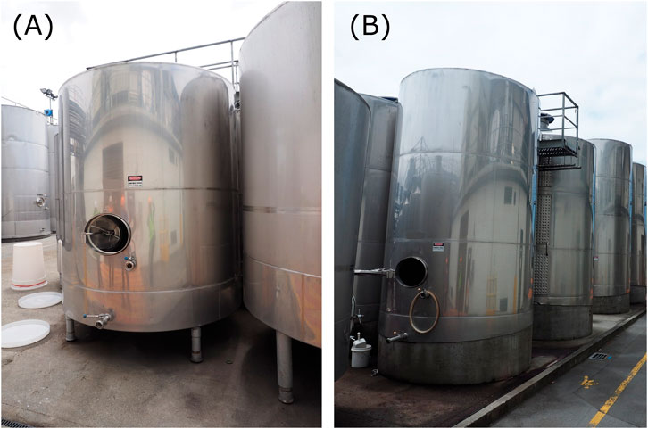
FIGURE 1. Examples of (A) a legged tank and (B) a flat-bedded tank.
The damage recorded in the wineries of Marlborough following the 2013 Seddon and 2016 Kaikōura earthquakes highlighted that wine tanks are the most vulnerable part of the wine production chain (Dizhur et al., 2017; Morris et al., 2013; Rosewitz and Kahanek, 2014). In recent years, damage to wine tanks has also been observed in major wine-producing and seismic-prone countries such as Argentina, Chile, Italy, and California (Brunesi et al., 2015; Fischer et al., 2016; González et al., 2013; Manos, 1991; Zareian et al., 2012). Empirical seismic fragility curves developed by Yazdanian et al. (2021) demonstrated that flat-based tanks performed better than legged tanks during the 2013 and 2016 earthquakes. Legged tanks reached complete damage at a lower median PGA (0.88 g) compared to flat-based tanks (1.0 g). It was also observed that the probability of experiencing complete damage was much higher for full tanks than for empty tanks (Yazdanian et al., 2021; Yazdanian et al., 2020a; Yazdanian et al., 2020b). Colombo et al. (2022) investigated the effect of the type of soil on the vulnerability of legged tanks. Seismic fragility curves were developed using incremental dynamic analysis using a set of Chilean ground motions. It was observed that the soil type had a significant influence on the variability and dispersion of the fragility curves. Legged tanks located on rock (soil type I) were more prone to damage. Bovo et al. (2020) developed fragility curves on 3-, 4-, and 5-leg tanks using incremental dynamics analyses on non-linear finite element models of steel tanks. Excessive sliding was the most frequent collapse mechanism for the three types of tanks. In the case of 4-leg tanks, leg buckling was reported to have a comparable occurrence as the sliding mechanism.
To improve the seismic behaviour of tanks, research has focused on seismic protection systems such as seismic isolation (Malhotra, 1997a; Malhotra, 1997b) and energy dissipator devices (Malhotra, 1998; Colombo and Almazán, 2015). More recently, Colombo and Almazán (2017) experimentally tested three configurations of legged tanks: (i) fixed base, (ii) isolated base with a multi-spring central leg and flat sliding bearings, and (iii) isolated only with flat sliding bearings. Results showed that while both (ii) and (iii) achieved similar shear and compression capacities, tanks isolated only with flat sliding bearings experienced excessive displacement not compatible with other auxiliary structures such as piping connections or catwalks. On the other hand, in the configuration with the multi-spring central leg, the restoring force generated reduced the residual displacement to less than 10 mm.
Currently, the seismic design of tanks is based on national recommendations “Seismic Design of Storage Tanks” released in 2009 by the New Zealand Society of Earthquake Engineering (NZSEE, 2009). Wine tanks are designed according to these NZSEE 2009 guidelines using importance level 1 (IL1), which defines the seismic load in the design actions standard (NZS 1170.5:2004). After the last decade of New Zealand earthquakes, the attribution of IL1 (structures presenting a low degree of hazard to life and other property) has been a subject of debate. It has been proposed to increase the design seismic acceleration, attributing to liquid tanks the importance level 2 (IL2) (Loporcaro et al., 2019; Watson, 2019). More importantly, the poor seismic performance of the anchorages/fasteners at the foundation interface highlighted that more guidance is needed. In fact, the NZSEE 2009 guidelines do not cover some critical specific aspects such as load paths, connection detailing, and capacity design principles (Au et al., 2015).
In this paper, the NZSEE 2009 guidelines are compared with two international codes on tank design: Eurocode 8 Part 4 (European Commission, 2006) and API 650 (American Petroleum Institute, 2021). This comparison is performed through the design of six wine tanks of different dimensions that are typically found in Marlborough wineries. The comparative analysis is limited to large tanks (>60,000 L) since, as shown in Section 2, they are the most common adopted typology and the most challenging to repair. The tanks are considered to be anchored to the foundation with anchor bolts. The objective is to investigate whether the NZSEE 2009 guidelines underestimate the design seismic load compared to the other standards and if EC8 or API 650 have a specific reference on wine tank design detailing that could complement the current New Zealand provisions.
2 Summary of the tank damage observed following the 2016 Kaikōura earthquake
The Marlborough region is located in the northeast of the South Island of New Zealand. The region has been struck by three major earthquakes over the last 10 years: the Cook Strait and Lake Grassmere earthquakes in 2013, both with a magnitude of Mw 6.6, and the Mw 7.7 Kaikōura earthquake on 14 November 2016. In all three events, wine tanks and other winery facilities sustained damage (Rosewitz and Kahanek, 2014). During the 2016 Kaikōura seismic event, the wineries inspected experienced horizontal peak ground accelerations (PGAs) ranging from 0.13 to 0.23 g (Dizhur et al., 2017). In Blenheim, the major city in the Malborough region, the design peak ground acceleration was 0.33 g (New Zealand Standards, 2004).
Earthquake damage to wine tanks is attributed to the following factors (Au et al., 2015; Yazdanian et al., 2021):
• The use of a thin shell of stainless steel for the tank walls.
• The distance between tanks is relatively small, causing tank pounding during the seismic shaking.
• The amount of wine in the tank during fermentation and storage.
• The slenderness of the tanks (H/R ranging between 3 and 5).
• Deficiencies in the design detailing of the critical connections.
The earthquake reconnaissance carried out after the 2016 Kaikōura earthquake showed that, overall, legged tanks sustained more damage than flat-bedded tanks. In particular, all legged tanks inspected that were full of wine sustained different degrees of damage. Damage varied from the failure of tank legs due to either bending (Figure 2A) or local buckling; pull-out of the anchoring systems; weld fracture at the connections between the top of the legs and the tank supporting beams; distortion and tearing of the tank floor; and the collapse of the support frame (Figure 2B) to overturning of the tanks that caused damage to the surrounding tanks and other facilities such as catwalks. On the other hand, empty tanks sustained no or minimal damage since the mass of the structure was extremely low.
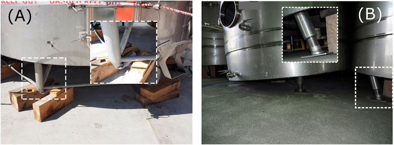
FIGURE 2. Damage on legged tanks: (A) bending of the lower part of the tank legs below the bracing; (B) partial collapse of the base of the tank due to excessive rotation of the tank legs.
Flat-bedded tanks on concrete plinths experienced different damage mechanisms (see Figure 3) due to the nature of the load transfer from the tank walls to the tank foundation via the skirting and the anchors. The anchors’ brackets were welded to the skirt and spaced at regular intervals. During the 2016 Kaikōura earthquakes, anchor rods experienced a range of failure mechanisms including fracture due to tension, shear, and buckling, anchor pull-out, stripping of the threads, and anchor bolt shear failure. In addition, local deformation and/or buckling of the skirting wall due to the rocking motion and horizontal movement during the earthquake were observed. Examples of anchorage damage are shown in Figures 4A–F.

FIGURE 3. Simplified scheme of the damage mechanisms in flat-bedded wine tanks.
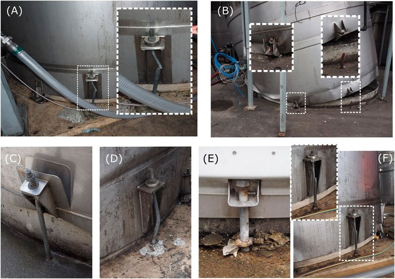
FIGURE 4. Damage of anchorage on flat-bedded tanks: (A) fracture of the rod due to excessive buckling; (B) collapse of the tank and fracture of the anchorage due to buckling (white box on the left) and excessive tension (white box on the right); (C) failure of the plate connecting the anchorage rod to the tank skirt; (D) buckling of the anchorage; (E) anchorage pull-out; and (F) anchorage tension fracture.
The stainless-steel tank walls were subjected to the following damage types: knuckle deformation, elephant foot buckling, and diamond buckling. The knuckle deformation is a deformation mechanism that localises at the base of the tank along the perimeter. It is caused by the rocking mechanism of the base of the tank on the concrete plinth, which has a diameter slightly smaller than the diameter of the tank (see Figures 5A,B). On the other hand, elephant foot buckling is an elastic–plastic deformation mode in the form of an outward bulge that is usually concentrated at the base of the tank (Figures 6A,B) or higher up the wall where its thickness reduces (Zhao and Zhou, 2018). Elephant foot buckling is caused by the combination of the compressive stress being larger than the tank wall critical stress and the hoop tensile stress being close to the yield stress of the steel (Niwa and Clough, 1982). Diamond buckling is the compression buckling mechanism of the tank wall (Figures 7A–C). This damage mechanism was typically observed on tanks whose capacity exceeded 10,000 L. In some cases, the excessive local buckling deformation caused tank perforation and wine loss. Although occasionally observed, deformation of the top cone of the tanks was not common. This was due to suction, as shown in Figure 8A, or localised damage caused by punching components of neighbouring tanks, as shown in Figure 8B. In other instances, damage to the top cone was attributed to the upward force produced by the sloshing liquid on the internal walls of the cone (Dizhur et al., 2017).
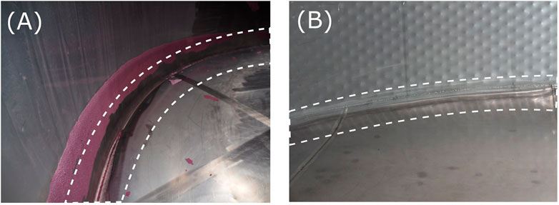
FIGURE 5. Knuckle deformation at the perimeter of the internal base of the tanks: (A) example 1 and (B) example 2.
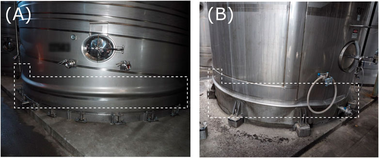
FIGURE 6. Elephant foot damage: (A) example 1 and (B) example 2.
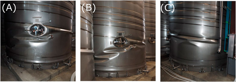
FIGURE 7. Three examples (A), (B), and (C) of diamond buckling on the wall of the tanks.
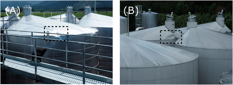
FIGURE 8. (A) Creasing of the top cone probably due to suction; (B) localised damage caused by a horizontal steel element.
Global tank collapse, i.e., overturning, occurred in several instances. The collapse resulted from the excessive rocking movements and displacement demands of the tanks. In some situations, the collapse of a tank caused a cascade effect resulting in the collapse of the neighbouring tanks (Figures 9A,B). A detailed summary of the damage inspection of the wineries in the Marlborough region after the Kaikōura earthquake can be found in Dizhur et al. (2017). The same damage mechanisms were observed on the infrastructure of wine tanks and wineries after the 1977 San Juan earthquake in Argentina (Manos, 1991), the 2010 Maule earthquake in Chile (Zareian et al., 2012; González et al., 2013), the 2012 Emilia earthquake in Italy (Brunesi et al., 2015), and the 2014 South Napa earthquake in California (Fischer et al., 2016).
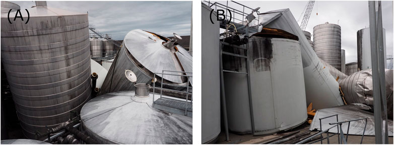
FIGURE 9. (A, B) Global collapse of slender tanks causing a cascade effect on neighbour tanks.
3 Seismic design standards and design philosophy
The dynamic pressure distribution exerted by a fluid against the walls and the base of a cylindrical tank fixed to the ground is presented in Figure 10A. Due to the lateral acceleration, the liquid mass near the free surface tends to create convective waves. The periods of the sloshing vibrations are generally in the high range, from 2 to 6–10 s, depending on the tank shape. Figure 10A shows an antisymmetric wave, corresponding to the lowest vibration frequency that presents a peak and a minimum. Modes with higher vibration frequencies show more peaks. The part of the fluid mass near the base of the tank tends to move rigidly with the tank (impulsive mode), enhancing the structure’s inertial mass. The percentage of liquid mass taking part in the convective mode varies with the ratio between the height and diameter of the tank (H/D). The lower the ratio, the higher this percentage will be. For the typical slenderness of wine tanks (H/D = 1.3–2.7), the part of the liquid that participates in the impulsive mode is more than 80%.
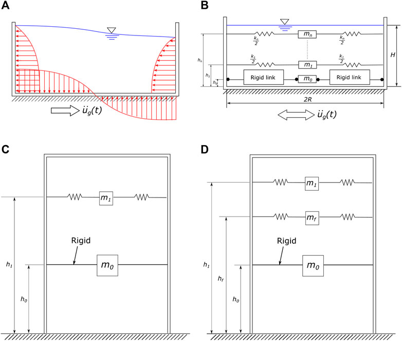
FIGURE 10. (A) Dynamic pressure distribution of a liquid in a tank during a ground motion. (B) Equivalent mechanical model. (C) Simplified mechanical model used by each code, which considers only
According to Housner (1957), the behaviour described has an equivalent mechanical model that is represented in Figure 10B, considering the tank wall as rigid. The mass denoted as
However, for aspect ratios in the range of H/D = 0.3–3, seismic forces can be evaluated with sufficient precision considering only
3.1 Tank flexibility
The 2009 NZSEE guideline proposes a more refined model that accounts for tank flexibility. A third term named “impulsive flexible” is introduced and can be considered uncoupled from the impulsive and convective modes. The “flexible” mass
This model is recommended for designing steel tanks when considering them as rigid and may be non-conservative, as in the case of wine tanks with a considerably slender height/radius ratio.
The code procedures compared are briefly named as follows:
• “NZSEE Flexible” indicates the 2009 NZSEE guidelines procedure that accounts for the flexible mode of vibration;
• “NZSEE Rigid” indicates the 2009 NZSEE guidelines procedure that considers the tank wall rigid;
• “EC8” for the “simplified procedure for fixed base cylindrical tanks” included in Annex A of EN 1998-4:2006;
• “API 650” for the API Standard 650 Welded Tanks for Oil Storage.
The procedure proposed by Eurocode 1998-4 for flexible tanks is not considered here. Each of the aforementioned standards provides a procedure for computing masses, the heights, and the periods of vibration of each mode. The acceleration related to each period of vibration is derived from the design spectrum. The acceleration is then multiplied by the mass, obtaining the contribution to the base shear. The overturning moment is calculated by multiplying the base shear and the height.
3.2 Rules of action combinations
Once the base shear contributions due to all modes of vibration are calculated, they are combined using Eq. 1.
where
Equation (2) combines the overturning moments.
where
The NZSEE guidelines and API 650 use Eq. 3 to combine the internal pressure terms, whereas EC8 uses Eq. 4 and considers Pv as an independent action not acting concurrently to Pr and Pf.
where
With the total force, the tank is then checked against hoop stress and wall buckling.
4 Case study: the design of six typical wine tanks
Front views and geometrical properties of the six archetype wine tanks that cover over 90% of the tank range in the Marlborough wineries used in the case study are presented in Figure 11. Each tank is designed following the NZSEE 2009 guideline, EC8, and API 650 in order to compare the differences in terms of seismic demand and detailing. The design location, which defines the elastic response spectrum, is the same for each procedure. The city selected is Blenheim, the main city in the Marlborough region; it is on a soft clay substrate. The elastic spectra used for designing the tanks were derived from NZS 1170.5:2004 (New Zealand Standards, 2004).
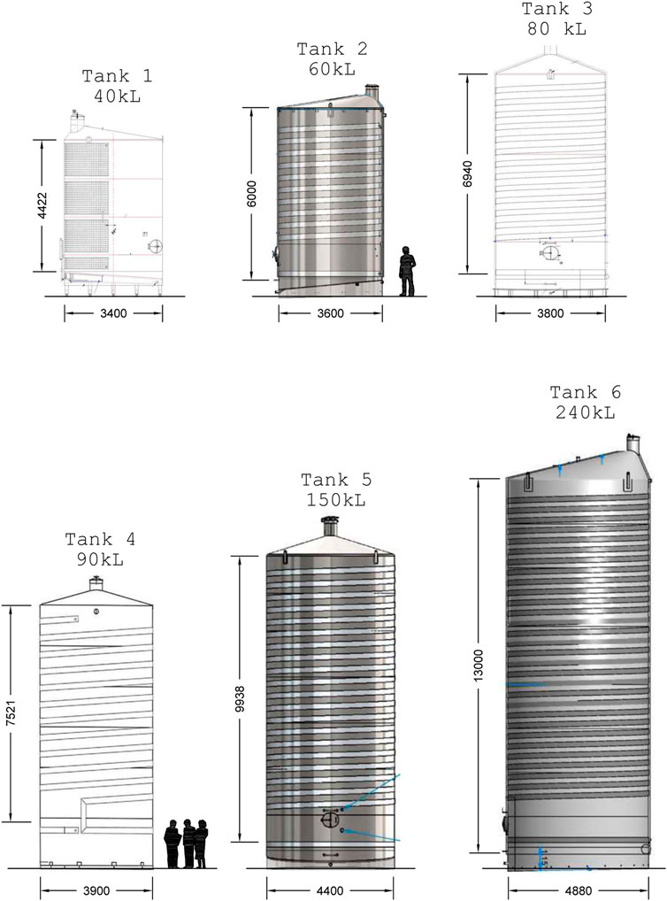
FIGURE 11. Geometrical properties of the tanks designed in the case study.
4.1 Geometry and material properties
Tank geometries used in this case study were selected to have an increased ratio between volume and slenderness. Table 1 summarises the geometrical properties of the tanks under investigation. The tanks were made by welding together sheets of stainless steel 304 (density = 8,000 kg/m3; elastic modulus = 193 GPa; and yielding stress = 205 MPa).
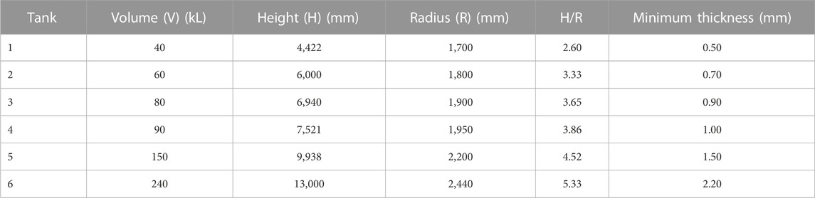
TABLE 1. Tank geometrical properties.
4.2 Preliminary design
The preliminary thickness of the tanks was obtained based on the simple procedure of API 650. Section 5.6.3 of API 650 provides equations defining the minimum thickness based on the steel-yielding stress and hydrostatic pressure. Table 1 shows the thickness assigned to each tank. The thickness is considered uniform along with the height.
4.3 Design response spectra
Two main features distinguish liquid storage tanks from buildings:
1. Tanks tend to have lower energy-dissipating capacity because they can accommodate fewer displacement demands and the detailing at the base cannot provide significant displacement ductility.
2. Tanks are subjected to hydrodynamic forces, which makes the prediction of the seismic demand more complicated.
Hydrodynamic forces are evaluated with a mechanical analogy in the form of the spring-mass system, which simulates the impulsive and convective modes of vibration. Codes define the increase in design seismic forces being proportional to the risk to life and the social and economic consequences of failure. The seismic forces are a function of the elastic acceleration spectrum, seismic zone factor, recurrence interval, PGA, soil factor, importance factor, response modification factor, and damping factor.
Table 2 summarises the definition of the importance level of the structure based on each code prescription. The importance level defines the seismic action recurrence interval, hence the PGA. PGAs derived from the three standards/guidelines are reported in Table 3. Table 4 shows the response modification factors that define the design spectrum shape.
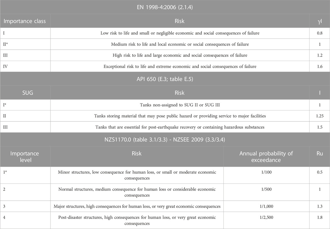
TABLE 2. Importance level definition.
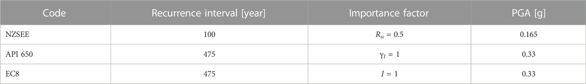
TABLE 3. Peak ground acceleration (PGA) according to NZSEE, API 650, and EC8.
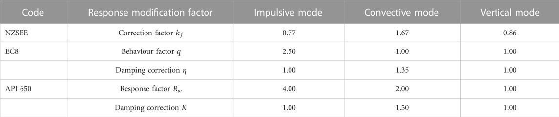
TABLE 4. Response modification factors according to NZSEE, API 650, and EC8.
Figure 12 shows the comparison of the design response spectrum that each code provides for the impulsive (A), convective (B), and vertical modes (C). Even if the recurrence interval of the NZSEE guidelines is lower, the response modification coefficients modify the design spectrum (impulsive and convective) to provide similar accelerations to those provided by EC8 and API 650. The EC8 impulsive mode design spectrum is 1% smaller than the NZSEE guidelines spectrum. The API 650 impulsive spectrum consists of a constant value which is 45% smaller than the NZSEE guideline spectrum. Using IL2 would double the NZSEE spectral acceleration at T = 0 s.

FIGURE 12. Design spectrum: (A) impulsive mode, (B) convective mode, and (C) vertical mode.
EC8 uses the elastic spectrum for the vertical mode, while NZSEE guidelines reduce the plateau value to 30% and API 650 reduces the plateau value to 14%. This difference is partly compensated when combining the effects: the NZSEE guidelines and API 650 use the SRSS (Eq. (3)), while the EC8 uses the 30% rule combination factor (Eq. (4)).
4.4 Masses and heights of force application
Section C3.3.1 of the NZSEE guidelines provides the participant mass of impulsive and convective modes m0 and m1 in a graphic form as a function of the H/R ratio. In Section A.2 of EC8, the impulsive and convective masses m0 and m1 are given by equations A.4 and A.12, respectively. Analogously, the participant mass of each mode is given in Section E.6.1.2 of API 650.
By comparing all three expressions, it is evident that they are identical since they build upon the research developed by Housner (1957). Thus, to compute the masses m0 and m1, EC8 expressions can be used for all six tanks. The impulsive participant mass is the most important since it contributes to 80%–90% of the total mass of each tank.
Furthermore, the NZSEE guidelines provide a plot for the portion of mass involved in the impulsive flexible mode of vibration
The NZSEE guidelines specify the heights
4.5 Periods of vibration
When the NZSEE guidelines are used, the designer can opt to account for the soil–structure interaction in the period calculation. As reported in Section C3.6, the soil–structure interaction may lengthen the period of vibration of the impulsive and vertical modes. The effects on the convective mode are small and can be neglected. In this design, the soil–structure interaction is used in both “rigid” and “flexible” procedures. Section A.7 of Eurocode 8 also describes the procedure for computing the period of vibration considering the soil–structure interaction. The expressions provided are the same as given in the NZSEE guidelines for rigid tanks. The design method in Appendix E of API 650 is independent of the impulsive period of the tank. Thus, the impulsive base shear coefficient shall be taken as the plateau value of the design spectrum. API 650 does not account for the vertical period. As for the impulsive mode, Section E.6.1.3 states that the vertical seismic coefficient shall be taken as 47% of the plateau value of the horizontal elastic spectrum. The fundamental periods of vibration for each tank and design code are presented in Table 5.
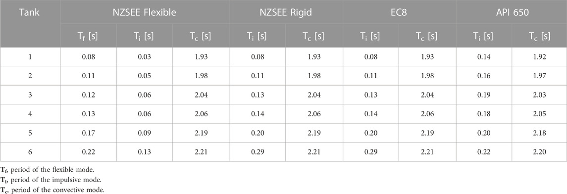
TABLE 5. Fundamental periods of vibration [seconds].
4.6 Base shear and overturning moment
Once the periods are known, it is possible to obtain the horizontal seismic coefficient
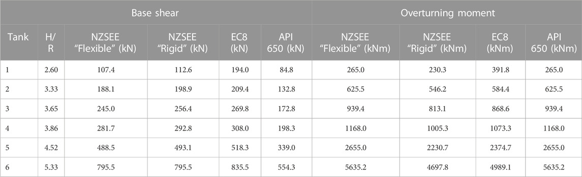
TABLE 6. Base shear and overturning moment.
The base overturning moment is the result of the multiplication of the base shear times the height of the force application. The total moment is obtained with the combination rule defined by Eq. (2). The results of the overturning moment are reported in Table 6.
The total base shear is very similar for both the procedures of the NZSEE guidelines and EC8 but approximately 30% less when calculated according to API 650. The overturning moment is maximum when the flexible procedure of NZSEE guidelines is used, which is 10% higher than EC8 and NZSEE “rigid” procedures and 40% higher than API 650 on average.
4.7 Hoop stress and wall buckling
The hoop stress and the wall buckling are the two main checks to avoid local failures of the tanks. The maximum values of hoop stress and vertical membrane compression stress for each tank are presented in Table 7.
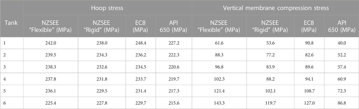
TABLE 7. Maximum hoop stress and vertical membrane compression stress.
The limit hoop stress shall not exceed the material yield stress, and the vertical shell compression shall not exceed the stress required to induce buckling in membrane compression. The equations to verify the aforementioned requirements are described in Section 5.5.2 of the NZSEE guidelines, Section 4.5.2 of EC8, and Section 6.2 of API 650. The procedures of each code allow the designer to resize the pre-designed thickness. As may be expected, the thickness pre-designed in Section 2.3 of this paper is not sufficient to verify the stress limits. Thus, all the tanks are re-designed to obtain the thicknesses presented in Table 8. The final wall thickness that each standard/guideline requires is comparable, although API 650 seems to have a more conservative approach considering that the vertical membrane and the hoop stresses are the lowest.
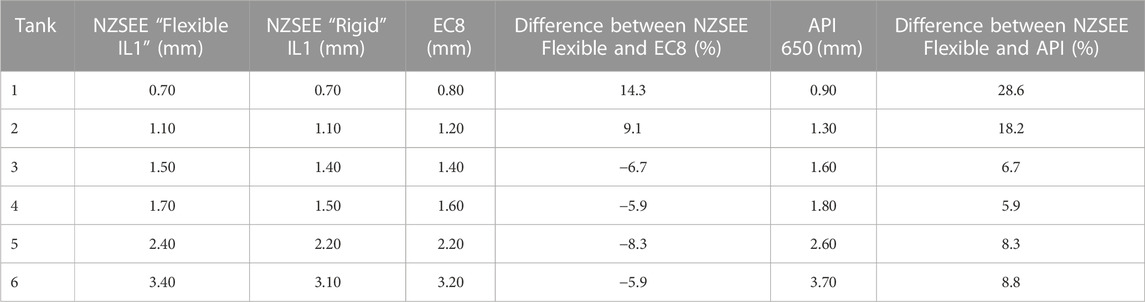
TABLE 8. Minimum thicknesses that verify the hoop stress and buckling limit.
4.8 Wall tank seismic design according to importance level 2 (2009 NZSEE guidelines)
In this section, the seismic design of tanks is performed according to the 2009 NZSEE guidelines using IL2. The results are then compared to those presented in the previous section, obtained by applying IL1.
As discussed in Section 4.3, applying IL2 doubles the spectral acceleration at peak when compared to IL2. Base shear, overturning moment, hoop and vertical stresses, and the minimum thickness of the tanks have been calculated using the “NZSEE Flexible” method for the six tanks. The results are compared with those obtained using IL1 in Tables 9, 10.
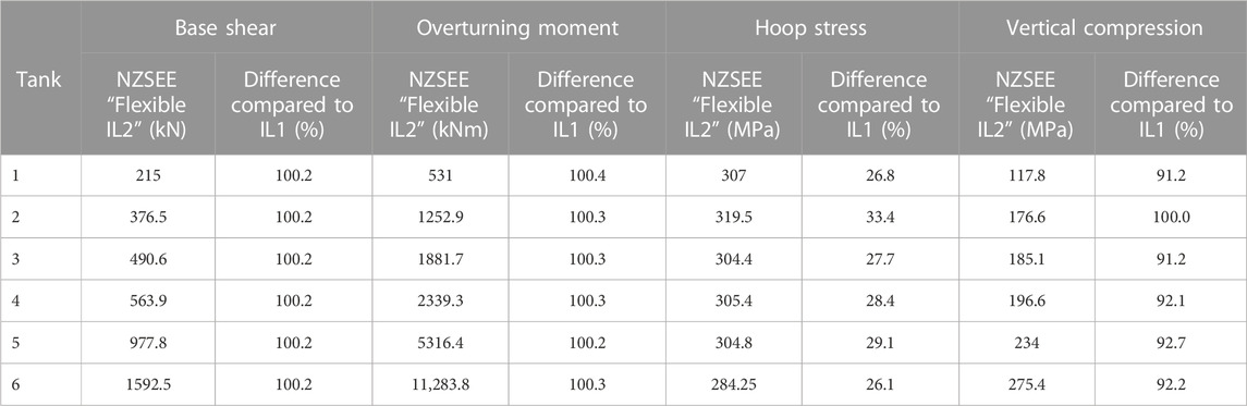
TABLE 9. Actions and stress values calculated according to the 2009 NZSEE guideline IL2.
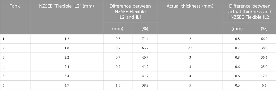
TABLE 10. Minimum thicknesses according to IL2 and actual tank wall thickness.
The base shear and overturning moment obtained for IL2 are as twice as those obtained assuming IL1. The average difference is 100.2% for the base shear and 100.3% for the overturning moment. The hoop stress and vertical membrane compression stress obtained for IL2 are on average 28.6% and 93.3% higher than those obtained for IL1, respectively. The minimum thickness required for verifying the hoop and compressive stresses is on average 50.5% higher than that calculated using IL1. The largest percentage thickness increase is observed for tank 1, where the minimum thickness required for IL2 is 71.43% higher than that required for IL1 (0.5 mm). The largest absolute thickness increase was observed for the largest tank (type 6, volume capacity 240 kL), which was 1.3 mm.
4.9 Base detail design criteria
Each standard provides equations about the detailing of the anchoring system. Section 5 of the NZSEE 2009 guidelines and its commentary section C5 provide two equations for the required hold-down force per unit length for anchored tanks, which are dependent on the ductility of the anchors.
where
Equation 5 is based on an anti-symmetric distribution of anchor forces [Figure 13A] and used for normal anchor bolts where fracture in a root thread can be expected. This equation is identical to API 650. Eq. 6 is used when the anchor ductility is ensured, i.e., where the anchors have been necked over a reasonable length to a diameter less than the root thread diameter. Eq. 6 is based on a triangular distribution [Figure 13B], with a compression force providing a reaction to the tie-down force, whose magnitude is expressed by Eq. 7.
where

FIGURE 13. Anchor factor distribution.
Equations 5 and 6 allow for designing the anchor diameter and spacing.
Section C5.1 of the NZSEE guidelines also adds that if a ductile dissipating system is available, like the ductile anchor bolts, a capacity design procedure should be used to ensure the desired method of energy dissipation. However, no guidance is provided on overstrength factors to be used for the anchors’ brackets/connections and all the other key components such as skirt-fastener connections and detailing footing–skirt–tank. As a result of this, as shown in Section 2, the damage to the tank–footing interface was substantial.
EC8 does not require any explicit verification of anchors. It only states (Section 3.5.2.3) that “(1) anchoring systems shall generally be designed to remain elastic in seismic design situations. However, they shall have a minimum nominal ductility to avoid brittle failures. The connection of anchoring elements to the structure and its foundation shall have an overstrength factor of not less than 1.25 with respect to the resistance of the anchoring elements. (2) If the anchoring system is part of the dissipative mechanisms, then it should be verified that it possesses the necessary ductility capacity” (Page 27, EN 1998-4:2006 Eurocode 8) (Commission, 2006). In addition to this clause, EC8 does not provide any procedure to design the anchor diameter and spacing and, more importantly, limits the design philosophy mainly to fully restrained, elastically designed tanks.
As discussed in Section 2, in the case of flat-bedded tanks, the plinth is surrounded by the skirt, which is an extension of the stainless-steel tank shell. The damage inspections after the Kaikōura earthquake have highlighted the importance of detailing this element. If not properly designed, the skirt can represent a weak element of the tank system, spreading the damage beyond the skirt itself to the tank wall. Figure 14A shows a skirt that has buckled around the anchors’ chairs.
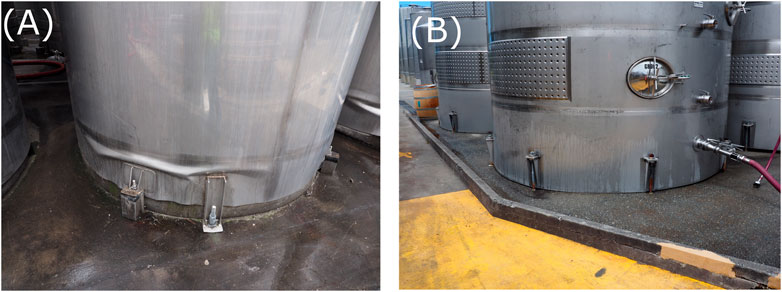
FIGURE 14. (A) Example of a damaged tank in which the lack of detailed design has caused skirt buckling; (B) example of an undamaged tank in which the steel skirt is extended to the concrete base slab.
In the case of some undamaged tanks, the skirt extended to the concrete slab at the base of the tank (Figure 14B). This arrangement has likely contributed to the transfer of the compression load evenly to the ground, avoiding stress concentration around the anchors’ chairs.
None of the standards/guidelines provides specifications on the detailing of the skirt. This leads to a lack of design that can result in unexpected damage and, in the worst scenarios, collapse.
4.10 Final discussion
When comparing the minimum thickness results obtained using the NZSEE Flexible, EC8, and API 650 standards, it can be seen that in the case of smaller tanks, NZSEE Flexible is less conservative; the calculated minimum thickness for types 1 and 2 is 14.3% (0.1 mm) and 9.1% (0.1 mm) smaller than that calculated using EC8. However, for larger tanks with volumes equal to or larger than 80 kL (types 3–6), NZSEE Flexible is slightly more conservative than EC8. On average, the thickness calculated using EC8 is approximately 7% (0.1 mm and 0.2 mm) smaller than that calculated according to NZSEE Flexible. On the other hand, as mentioned, API 650 is overall more conservative than the other codes. On average, the minimum thickness calculated according to API 650 is 0.2 mm larger than that obtained from NZSEE Flexible. This difference is extremely small. Moreover, since the manufacturer’s tolerance is not less than 0.5 mm, it is expected that the thickness that the designer chooses will eventually be similar. In conclusion, the results provided show that assigning an IL1, according to the 2009 NZSEE Guidelines for Seismic Design of Storage Tanks, does not underestimate the seismic design of wine tanks when compared to similar codes such as Eurocode 8: Design of structures for earthquake resistance, Part 4-Silos, Tank and Pipelines and API Standard 650: Welded Tanks for Oil Storage.
An increase in the importance level from 1 to 2 leads to an increase in wall thickness of approximately 50%. In Table 10, the thickness used in actual tanks of similar dimensions is provided and compared with the minimum design thickness obtained following the 2009 NZSEE guidelines with IL2. The thickness calculated is higher than the minimum thickness required by IL2 for all six tanks. This difference ranges from 0.3 mm (for tank 6) to 0.8 mm (for tank 1), which, respectively, corresponds to 6.4% to 66.7%.
These results indicate that the damage suffered by the wine tanks during the 2013 Seddon and 2016 Kaikōura earthquakes is not related to the application of a higher importance level. The wall tank thicknesses used in actual tanks are most likely larger than the minimum thickness designed according to the 2009 NZSEE Guidelines for Seismic Design of Storage Tanks assuming IL2.
Based on the presented evidence, it can be inferred that the damage resulting from the 2013 and 2016 earthquakes may be attributed to the lack of design and detailing of the critical connections at the tank–footing interface.
5 Conclusion
The design criteria, according to 2009 NZSEE Guidelines for Seismic Design of Storage Tanks, Eurocode 8: Design of structures for earthquake resistance, Part 4-Silos, Tank and Pipelines, and API Standard 650: Welded Tanks for Oil Storage, are compared through the design of six wine tanks of different dimensions.
The comparison has highlighted the following:
• The three standards/guidelines are based on the well-known dynamic behaviour of liquid storage tanks, which considers impulsive and convective modes. For values of slenderness typical of the tanks investigated in this research, the impulsive mode is dominant with 80%–90% of the total mass.
• The NZSEE guidelines provide a procedure that takes into consideration the tank flexibility, which results in a higher overturning moment as the slenderness of the tank increases. Each standard uses response modification coefficients to convert the elastic spectrum into the design spectrum. These coefficients account for ductility, damping, and importance level. The latter establishes the recurrence interval of the PGA. For EC8 and API 650, it is 500 years, while for the NZSEE guidelines, it is only 100 years. Although the recurrence interval of the NZSEE guidelines is lower, its impulsive mode design spectrum is the highest. The EC8 impulsive mode design spectrum is 1% smaller than the NZSEE guidelines spectrum. The API 650 impulsive spectrum consists of a constant value, i.e., 45% smaller than the NZSEE guidelines spectrum.
• For the six tanks designed in this case study, the NZSEE guidelines procedure gives results comparable to EC8 and API 650 in terms of the minimum thickness of the walls. Therefore, the current NZSEE guidelines do not underestimate the seismic design of wine tanks when compared to the other two standards.
• The design of tanks according to the NZSEE guidelines and assigning an IL2 (normal structures, medium consequence for human loss, or considerable economic consequences) increases the minimum tank wall thickness, on average, by 50%. However, these values are still smaller than the actual thickness values reported in real tanks of similar dimensions damaged during the 2013 and 2016 earthquakes. Concerning detailing, the design criteria specified by the three standards provide suggestions only on the minimum anchorage. API 650 and EC8 state that the designer shall consider the anchorage to remain elastic in case of seismic events. Instead, NZSEE guidelines allow for the selection of different equations depending on whether or not ductile anchors are used. No further guidance is given to design the complete load path from the tank shell to the ground, including anchors, anchor chairs, skirt, plinth, and footing resistance against the tank’s tension–compression reactions and pull-out.
• Increasing the importance level would not protect the tanks against poorly designed details. This lack of provisions for capacity design led to unexpected damage and collapses. Although the NZSEE guidelines are more exhaustive than the EC8 and API 650, improvements should be focused on the design and detailing of critical connections,
• Further numerical and experimental campaigns are necessary to fully understand the interaction among all the structural components at the tank–footing interface.
• EC8, API 650, and partly 2009 NZSEE guidelines should extend their current versions to the scenario where seismic protective devices/isolators and dissipative anchors including friction- and viscous-based anchors are adopted since new proprietary products are already available and implemented in the wine industry.
Author contributions
MF is the main author of the article. He carried out the research and wrote the main parts of the paper. GL wrote two sections of the paper, co-supervised the research, reviewed the paper, prepared images, and coordinated the manuscript preparation. NB and AP supervised the research project and reviewed the paper extensively. AW was the industry supervisor and expert in the seismic design of wine tanks in New Zealand. He reviewed the paper and provided industry technical support during the research. All authors contributed to the article and approved the submitted version.
Acknowledgments
The authors would like to thank Regan Wood (Cook Costello, Christchurch, New Zealand) for the information provided during the reconnaissance.
Conflict of interest
AW was employed by the company Kotahi Engineering Studio.
The remaining authors declare that the research was conducted in the absence of any commercial or financial relationships that could be construed as a potential conflict of interest.
The handling editor SS declared a shared affiliation with the authors MF and NB at the time of review.
Publisher’s note
All claims expressed in this article are solely those of the authors and do not necessarily represent those of their affiliated organizations, or those of the publisher, the editors, and the reviewers. Any product that may be evaluated in this article, or claim that may be made by its manufacturer, is not guaranteed or endorsed by the publisher.
References
American Concrete Institute (Aci), (1997). Standard practice for design and construction of concrete silos and stacking tubes for storing granular materials and commentary. Farmington Hills, Michigan: American Concrete Institute. ACI, 313-97–313-R97.
American Petroleum Institute, (2021). API standard 650: Welded tanks for oil storage. Washington, United States: American petroleum institute.
Architectural Institute of Japan (Aij), (2010). Design recommendation for storage tanks and their supports with emphasis on seismic design. Tokyo, Japan: AIJ.
Au, E. V., Walker, A. F., and Lomax, W. J. (2015). “Wine industry implementation of the NZSEE guidance on the seismic design of liquid storage tanks,” in 2015 New Zealand Society for Earthquake Engineering (NZSEE) conference, Rotorua, New Zealand, November 2015.
Bovo, M., Barbaresi, A., and Torreggiani, D. (2020). Definition of seismic performances and fragility curves of unanchored cylindrical steel legged tanks used in wine making and storage. Bull. Earthquake Eng. 18, 3711–3745. doi:10.1007/s10518-020-00841-z
Brunesi, E., Nascimbene, R., Pagani, M., and Beilic, D. (2015). Seismic performance of storage steel tanks during the may 2012 Emilia, Italy, earthquakes. J. Perform. Constr. Facil. 29 (5), 04014137. doi:10.1061/(ASCE)CF.1943-5509.0000628
Colombo, J., and Almazán, J. (2017). Experimental investigation on the seismic isolation for a legged wine storage tank. J. Constr. Steel Res. 133, 167–180. doi:10.1016/j.jcsr.2017.02.013
Colombo, J. I., and Almazán, J. L. (2015). Seismic reliability of continuously supported steel wine storage tanks retrofitted with energy dissipation devices. Eng. Struct. 98, 201–211. doi:10.1016/j.engstruct.2015.04.037
Colombo, J. I., Wilches, J., and Leon, R. (2022). Seismic fragility of legged liquid storage tanks based on soil type classifications. J. Constr. Steel Res. 192, 107212. doi:10.1016/j.jcsr.2022.107212
Dizhur, D., Simkin, G., Giaretton, M., Loporcaro, G., Palermo, A., and Ingham, J. (2017). Performance of winery facilities during the 14 November 2016 Kaikōura earthquake. Bull. N. Z. Soc. Earthq. Eng. 50 (2), 206–224. doi:10.5459/bnzsee.50.2.206-224
European Committee for Standardization (2006). EN 1998-4:2006 Eurocode 8: Design of structures for earthquake resistance, Part 4 -silos, tank and Pipelines. Brussels, Belgium: CEN.
Fischer, E. C., Liu, J., and Varma, A. H. (2016). Investigation of cylindrical steel tank damage at wineries during earthquakes: Lessons learned and mitigation opportunities. Pract. Periodical Struct. Des. Constr. 21 (3), 04016004. doi:10.1061/(ASCE)SC.1943-5576.0000283
González, E., Almazán, J., Beltrán, J., Herrera, R., and Sandoval, V. (2013). Performance of stainless steel winery tanks during the 02/27/2010 Maule Earthquake. Eng. Struct. 56, 1402–1418. doi:10.1016/j.engstruct.2013.07.017
Haroun, M. A., and Housner, G. W. (1981). Seismic design of liquid storage tanks. J. Tech. Counc. ASCE 107 (1), 191–207. doi:10.1061/JTCAD9.0000080
Hosseini, S. E. A., and Beskhyroun, S. (2023). Fluid storage tanks: A review on dynamic behaviour modelling, seismic energy-dissipating devices, structural control, and structural health monitoring techniques. Structures 49, 537–556. doi:10.1016/j.istruc.2023.01.146
Housner, G. W. (1957). Dynamic pressures on accelerated fluid containers. Bull. Seismol. Soc. Am. 47 (1), 15–35. doi:10.1785/BSSA0470010015
Housner, G. W. (1963). The dynamic behavior of water tanks. Bull. Seismol. Soc. Am. 53 (2), 381–387. doi:10.1785/BSSA0530020381
Jacobsen, L. S. (1949). Impulsive hydrodynamics of fluid inside a cylindrical tank and of fluid surrounding a cylindrical pier. Bull. Seismol. Soc. Am. 39 (3), 189–204. doi:10.1785/BSSA0390030189
Khalil, M., Ruggieri, S., and Uva, G. (2022). Assessment of structural behavior, vulnerability, and risk of industrial silos: State-of-the-Art and recent research trends. Appl. Sci. 12 (6), 3006. doi:10.3390/app12063006
Loporcaro, G., Palermo, A., Campbell, W. J., Hyndman, D. C., Walker, A., and Wood, R. (2019). “Post-earthquake recovery phase of winery facilities,” in A case study in the Marlborough area 2019 Pacific Conference on Earthquake Engineering, Auckland, New Zealand, 2019.
Malhotra, P. K. (1997a). Method for seismic base isolation of liquid-storage tanks. J. Struct. Eng. 123 (1), 113–116. doi:10.1061/(asce)0733-9445(1997)123:1(113)
Malhotra, P. K. (1997b). New method for seismic isolation of liquid-storage tanks. Earthq. Eng. Struct. Dyn. 26 (8), 839–847. doi:10.1002/(sici)1096-9845(199708)26:8<839::aid-eqe679>3.0.co;2-y
Malhotra, P. K. (1998). Seismic strengthening of liquid-storage tanks with energy-dissipating anchors. J. Struct. Eng. 124 (4), 405–414. doi:10.1061/(asce)0733-9445(1998)124:4(405)
Malhotra, P. K. (2005). Sloshing loads in liquid-storage tanks with insufficient freeboard. Earthq. Spectra 21 (4), 1185–1192. doi:10.1193/1.2085188
Malhotra, P. (2000). Practical nonlinear seismic analysis of tanks. Earthq. Spectra 16 (2), 473–492. doi:10.1193/1.1586122
Manos, G. C. (1991). Evaluation of the earthquake performance of anchored wine tanks during the San Juan, Argentina, 1977 earthquakexs. Earthq. Eng. Struct. Dyn. 20 (12), 1099–1114. doi:10.1002/eqe.4290201202
Mansour, S., Pieraccini, L., Palermo, M., Foti, D., Gasparini, G., Trombetti, T., et al. (2022a). Comprehensive review on the dynamic and seismic behavior of flat-bottom cylindrical silos filled with granular material. Front. Built Environ. 7, 182. doi:10.3389/fbuil.2021.805014
Mansour, S., Silvestri, S., and Sadowski, A. J. (2022b). The ‘miniature silo’test: A simple experimental setup to estimate the effective friction coefficient between the granular solid and a horizontally-corrugated cylindrical metal silo wall. Powder Technol. 399, 117212. doi:10.1016/j.powtec.2022.117212
Morris, G. J., Bradley, B. A., Walker, A. F., and Matuschka, T. (2013). Ground motions and damage observations in the Marlborough region from the 2013 lake Grassmere earthquake. Bull. N. Z. Soc. Earthq. Eng. 46 (4), 169–187. doi:10.5459/bnzsee.46.4.169-187
New Zealand Society for Earthquake Engineering (Nzsee), (2009). Seismic design of storage tanks: 2009. Wellington, New Zealand: Recommendations of a NZSEE Study Group.
New Zealand Standards, (2004). NZS 1170.5:2004 Structural design actions. Part 5:earthquake actions – New Zealand. Wellington, New Zealand: Standard New Zealand.
New Zealand Wine Growers Inc, (2022). Annual report 2022 New Zealand wine. New Zealand: New Zealand Wine Growers Inc.
Niwa, A., and Clough, R. W. (1982). Buckling of cylindrical liquid-storage tanks under earthquake loading. Earthq. Eng. Struct. Dyn. 10 (1), 107–122. doi:10.1002/eqe.4290100108
Rosewitz, J., and Kahanek, C. (2014). “Performance of wine storage tanks,” in lessons from the earthquakes near Marlborough ASEC 2014 Conference, Auckland and Christchurch, 2014.
Veletsos, A. (1974). “Seismic effects in flexible liquid storage tanks,” in Proceedings of the 5th world conference on earthquake engineering, Rome, Italy, June 1974, 630–639.
Yazdanian, M., Ingham, J. M., Kahanek, C., and Dizhur, D. (2020a). Damage to flat-based wine storage tanks in the 2013 and 2016 New Zealand earthquakes. J. Constr. Steel Res. 168, 105983. doi:10.1016/j.jcsr.2020.105983
Yazdanian, M., Ingham, J. M., Kahanek, C., and Dizhur, D. (2020b). Damage to legged wine storage tanks during the 2013 and 2016 New Zealand earthquakes. J. Constr. Steel Res. 172, 106226. doi:10.1016/j.jcsr.2020.106226
Yazdanian, M., Ingham, J., Sadashiva, V., Cutfield, M., Kahanek, C., and Dizhur, D. (2021). Seismic fragility curves for stainless-steel wine storage tanks. Structures 33, 4766–4780. doi:10.1016/j.istruc.2021.07.054
Zareian, F., Sampere, C., Sandoval, V., McCormick, D. L., Moehle, J., and Leon, R. (2012). Reconnaissance of the Chilean wine industry affected by the 2010 Chile offshore Maule earthquake. Earthq. Spectra 28 (S1), S503–S512. doi:10.1193/1.4000048
Keywords: wine tanks, seismic design of tanks, liquid tanks, design code reviews, winery industry
Citation: Frezzati M, Loporcaro G, Buratti N, Palermo A and Walker A (2023) Design code review on seismic demand and base detailing criteria: an application to wine tanks in Marlborough. Front. Built Environ. 9:1167237. doi: 10.3389/fbuil.2023.1167237
Received: 16 February 2023; Accepted: 07 June 2023;
Published: 22 June 2023.
Edited by:
Stefano Silvestri, University of Bologna, ItalyCopyright © 2023 Frezzati, Loporcaro, Buratti, Palermo and Walker. This is an open-access article distributed under the terms of the Creative Commons Attribution License (CC BY). The use, distribution or reproduction in other forums is permitted, provided the original author(s) and the copyright owner(s) are credited and that the original publication in this journal is cited, in accordance with accepted academic practice. No use, distribution or reproduction is permitted which does not comply with these terms.
*Correspondence: Giuseppe Loporcaro, giuseppe.loporcaro@canterbury.ac.nz