 Serena Gambarelli1*
 R. Noé Fararoni Platas1
 Arvinth Shankar1
 Spasena Dakova2
 Michael Böhm2Oliver Sawodny2
 Markus Nitzlader3
 Lucio Blandini3
- 1Material Behavior and Modeling Unit, Materials Testing Institute, University of Stuttgart, Stuttgart, Germany
- 2Institute for System Dynamics, University of Stuttgart, Stuttgart, Germany
- 3Institute for Lightweight Structures and Conceptual Design, University of Stuttgart, Stuttgart, Germany
In the present study, the adaptive behavior of a concrete beam with integrated fluidic actuators was numerically investigated through three-dimensional (3D) non-linear finite element (FE) analysis. The employed numerical approach for the mechanical behavior of concrete is based on the microplane theory, implemented in the in-house software MAcroscopic Space Analysis (MASA). Different cases were analyzed and the results compared with experimental tests available in the literature. First, a reference concrete beam without actuators was numerically analyzed in order to calibrate and validate the employed non-linear microplane material model. Thereafter, the validated model was used for the non-linear analysis of the concrete beam with integrated fluidic actuators, with respect to different load cases. The obtained results confirm the capability of the model to reproduce the deformational behavior of the beam for all analyzed cases. A fundamental aspect is the realistic modeling of the actuators and related applied pressure. The use of a non-linear material model allows to realistically capture the possible cracking and consequent failure of the beam. It is worth mentioning that a full model validation should be extended to the long-term behavior of actuated structural elements. In future perspective, the well-established numerical framework for concrete, based on coupled 3D hygro-thermo-mechanical model, can be used to 1) investigate the performance of adaptive structural components, with respect to more complex loading conditions, e.g., cyclic; 2) perform durability analysis under exposure to different combinations of mechanical and/or environmental loading conditions.
1 Introduction
The use of lightweight structures and components in building construction has largely increased over the years due to the advantages related to reduced material and energy consumption (United Nations Environment Programme, 2020). However, one limitation is the large deformation of structural elements induced by external loads. As underlined by Wagner et al. (2019), the concept of adaptivity can significantly reduce this problem by adapting the load-bearing behavior of structural elements or an entire structure with respect to the changing external loads (static or dynamic). Adaptive structures include actuators, sensors and a control system. A fundamental aspect of the adaptive behavior is to compensate for stress peaks and deformations induced by conventional loads and/or self-weight (passive state) through actuators (Geiger et al., 2020; Senatore and Reksowardojo, 2020; Reksowardojo et al., 2022), which can deform the structural elements in a positive manner (active state). The combination of the two states is called adaptive state: in this state, the deformation is significantly reduced in comparison to the passive state.
The use of fluidic actuators embedded into reinforced concrete (RC) beams and slabs subjected to bending is largely investigated in the framework of the Collaborative Research Centre (SFB) 1244 “Adaptive Skins and Structures for the Built Environment of Tomorrow” at the University of Stuttgart (Sobek et al., 2021; Nitzlader et al., 2022). The concept of integrated actuators is alternative to that of externally added actuators. In the first case, a hydraulic pressure chamber is positioned in the compressive zone of the structural element, at specific distance from the neutral axis. Through the hydraulic pressure applied to an actuator, its chamber expands. The resulting constraint force component, together with the inner lever arm, generates actuation bending moments which can counteract the moments from conventional loads. This form of actuation generates mainly compressive stresses on the left and right sides of the pressure chamber (longitudinal axis). Above and below the actuator, in the area of the pressure chamber, tensile stresses are introduced which can be superimposed with the compressive stresses from conventional loads, in the adaptive state (see Kelleter et al., 2020). The chamber pressures are adjusted in the internal control loop (see, e.g., Wagner et al., 2019) in order to compensate the deflection induced by external loads.
The geometry and position of the actuators inside the beam play a fundamental role in the adaptive performance of the beam. Some studies in the literature are focused on the optimization of the actuator placement and static load compensation, see Heidingsfeld et al. (2017), Wagner et al. (2018) and Wagner et al. (2019). Different applications of such actuators can also be found in Kelleter et al. (2020), Kelleter (2022), Burghardt et al. (2022), Stiefelmaier et al. (2022), and Stiefelmaier et al. (2023).
The cracking behavior of passive RC beams has been extensively investigated in the past both experimentally and numerically (Hillerborg et al., 1976; Ibrahimbegovic et al., 2010; Jason et al., 2013). In particular, different numerical approaches were proposed in the literature for the fracture behavior of concrete, based on plasticity theory, damage mechanics, smeared crack models, microplane model, etc. (see Jirásek, 2012). However, a few numerical studies have focused on the performance of adaptive RC elements by means of 3D FE analysis, e.g., Kelleter et al. (2020) and Kelleter (2022). Kelleter (2022) investigated the adaptive behavior of a concrete beam with integrated fluidic actuators both experimentally and numerically. For the numerical simulations, the isotropic linear elastic model was employed in the commercial software ABAQUS. Two additional simulations were carried out by Kelleter (2022) with the elasto-plastic damage model (concrete damage plasticity) to capture the cracking behaviour of the concrete beam. As underlined by the author, the isotropic scalar damage model was employed to describe the cracking process, which has no general validity for concrete.
In the present study, the non-linear microplane material model implemented into the 3D FE code MASA (Ožbolt, 1998) is used to numerically investigate the adaptive behavior of the concrete beam with integrated actuators reported by Kelleter (2022). Unlike tensorial formulations for quasi-brittle materials based on plasticity and/or damage theory, in the microplane model (Ožbolt et al., 2001) the material constitutive law is defined through uniaxial stress-strain relationships along different orientations surrounding the numerical integration (Gauss) points of the FE model. The main advantage of the model over standard tensorial approaches is the fact that the macroscopic stress tensor is obtained through consistent integration of stresses that are monitored over the different pre-defined directions (microplanes). This methodology is really beneficial in case of complex loading conditions, e.g., three-dimensional cycling loading. The interaction between the directions is automatically accounted for as well as the damage induced anisotropy. Moreover, through definition of weak direction(s) of the material it is easy to account for the initial anisotropy. This kind of approach is very suitable for the non-linear analysis of building materials with heterogeneous structure, i.e., concrete and wood (Gambarelli and Ožbolt, 2021; Ožbolt et al., 2022).
In this study, the microplane parameters for the nonlinear material model were properly calibrated based on the tensile and compressive strength properties of the C35/45 concrete used in the experiments described by Kelleter (2022). After this calibration, the nonlinear model was validated against the reference concrete beam (without actuators) tested by Kelleter (2022). Thereafter, the nonlinear model was used to analyze the adaptive behavior of the beam with integrated actuators, with respect to three different configurations, namely, U1, R2 and M1 as noted in Table 1. The obtained results show that the nonlinear model correctly reproduces the deformational behavior of the beam for all analyzed cases. Moreover, the use of the nonlinear material model allows to realistically capture the possible cracking and consequent failure of the beam. As an additional motivation, this validated model is useful as supportive tool for the calibration of the control loop of an adaptive structural element with respect to failure prediction and in general for the design process of the controlled system, extending the work of Stiefelmaier et al. (2023) to failure of structural elements. For example, an online classifier trained based on the model could be used to constrain the pressure in the chambers to values for which a structural failure is highly unlikely.
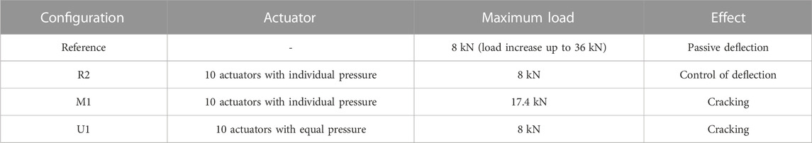
TABLE 1. Overview of the analyzed cases.
The derived nonlinear model may also be used to extend the ideas presented by Heidingsfeld et al. (2017) and Wagner et al. (2018) to optimally place actuators in order to prevent failure such as cracking. In the same fashion, sensors could be placed optimally for early detection of plastic deformations in an extension of Stiefelmaier et al. (2022).
The main contribution of this paper lies in the modeling of an adaptive RC beam using the nonlinear microplane model and in the validation by comparison of the numerical results with the experiments from Kelleter (2022). The results also give insight into some of the specifics of the actuation, especially the geometric parameters that need to be adapted for optimal matching of experiment and numerical model.
The paper is organized as follows. The experimental tests carried out by Kelleter (2022) are described in Section 2. The employed FE model and material parameters are reported in Section 3. The obtained numerical results are discussed in Section 4, based on the comparison with the experimental and numerical data by Kelleter (2022). Finally, the main conclusions are given in Section 5.
2 Experimental tests from the literature
Among the tests carried out by Kelleter (2022), the following cases were numerically investigated in the present study (Table 1). All the experimental test results will be discussed in Section 4 for comparison with the numerical ones.
2.1 Concrete (reference) beam without actuators
A four-point bending test was carried out by Kelleter (2022) on a simply supported concrete beam without actuators. The geometry of the beam and the test setup are shown in Figure 1A. A minimum bottom and top reinforcement avoid a premature cracking of the beam. The two-points vertical load is applied through a steel plate (IPE 100) on the top part of the concrete beam. The applied force is gradually increased from 0 kN to a maximum of 8 kN. The maximum displacement of the mid-node of the upper edge of the beam is measured at the end of the test. The horizontal strain profiles for the upper and bottom edges of the beam are also reported by Kelleter (2022).
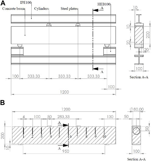
FIGURE 1. (A) Reference beam and its test setup. (B) Geometry of the concrete beam with actuators. Dimensions in milimeters.
2.2 Concrete beam with actuators
A concrete beam with 10 integrated hydraulic fluidic actuators was tested by Kelleter (2022) under different loading conditions. The geometry of the beam is shown in Figure 1B. The test setup for the four-point bending test is the same as shown in Figure 1A. The steel actuators consists of two steel sheets and a spacer ring. The two outer sheets have a thickness of 1 mm, the inner ring is 2 mm thick. The inner sheet is ring-shaped and has a flange height of 5 mm, which prevents expansion in the radial direction (Figure 2A). Since the inner ring is significantly stiffer in the radial direction than the two outer sheets perpendicular to the plane of the sheets, hydrostatic internal pressure predominantly results in an expansion transverse to the actuator, i.e., along the longitudinal axis of the beam (see Kelleter, 2022). The function of the inner ring is to create a defined cavity. The three steel sheets are, after attaching a hydraulic pipe with an outer diameter of 4 mm from the same material, welded at the edge. Ignoring this pipe, the actuator is circular and has an outside diameter (DA) of 80 mm (see Figure 2A). The inner diameter is equal to 70 mm. Figure 2B shows the beam before casting reported by Kelleter (2022). The actuators are fixed in position via the pipes. In order to better secure the position, the beam is rotated by 180°. In the configuration shown, the pipes are routed laterally out of the cross-section.
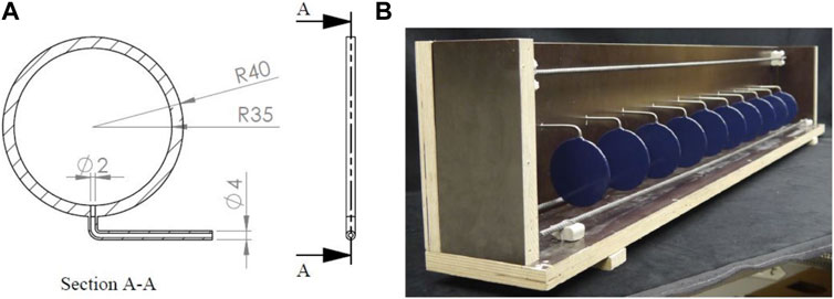
FIGURE 2. (A) Geometry of the steel actuator. (B) Opened formwork of the 180° rotated beam with 10 aligned actuators and the reinforcement bars [taken from the PhD thesis of Kelleter (2022)].
2.2.1 Configuration R2
In the R2 configuration a pressure of 5 bar is first applied in each actuator to compensate the self-weight of the beam. This results in an initial positive y-displacement of the mid-node in the upper edge of the beam equal to 0.014 mm (according to the coordinate system in Figure 3). Thereafter, the vertical load and the pressure in the actuators are increased simultaneously until the maximum load of 8 kN is fully applied. The pressure value is adjusted in each actuator such that the moment generated can compensate the moment produced by the applied load. The maximum average pressures achieved in the actuators are summarized in Table 2. The corresponding positions of the actuators are shown in Figure 1B.
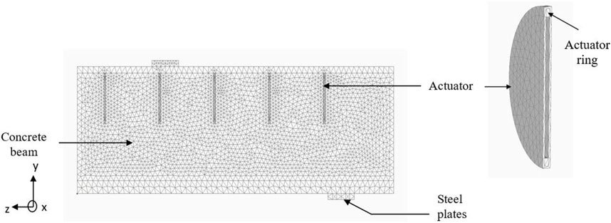
FIGURE 3. FE discretization of a quarter of the concrete beam with actuators (2D view).
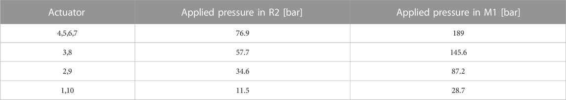
TABLE 2. Applied pressures in the actuators (configuration R2 and M1).
2.2.2 Configuration M1
The main objective of the M1 configuration is to investigate the cracking behavior of the beam. For this purpose, the vertical load is increased until a maximum value of 17.4 kN. Simultaneously, the pressure in the actuators is also increased gradually, until each actuator reaches its individual maximum pressure, corresponding to the fully applied compensation. The average values of the maximum applied pressures are summarized in Table 2.
2.2.3 Configuration U1
In the U1 configuration the vertical load is applied until a maximum of 8 kN is reached (passive state). Thereafter, equal pressures are gradually applied in the actuators until a maximum value of 97 bar. At a pressure of around 50 bar, the displacement of the mid-node in the upper edge of the beam is fully compensated. For higher values of the applied pressure, some cracks are observed in the upper part of the concrete beam, starting from the outer actuators. The test is terminated at 97 bar.
2.3 Considerations on the measured pressures in the actuators
It is worth mentioning that three experimental tests on individual actuators were also performed by Kelleter (2022) to verify the linearity of the relationship between the hydraulic pressure applied in the actuators and the related force. For this purpose, the actuators were clamped into the testing machine and subjected to hydraulic pressure. The pressure (pA,i) was continuously increased to pA,1 = 169 bar in the first, to pA,2 = 181 bar in the second and to pA,3 = 180 bar in the third test. This results in a maximum theoretical force (FA,i = A pA,i) of respectively 82 kN, 89 kN and 83 kN, with an area of the actuators (A) equal to 3846.5 mm2. The measured forces during the tests were in all cases higher than the theoretical values, with deviation ranging between 16.1% and 22.4%. A similar deviation in all three actuators shows a systemic underestimation of the hydraulic pressure. As explained by Kelleter (2022), this can be due to the fact that the effective diameter available to the pressure is larger than the inner diameter (Din = 70 mm), since the three plates are welded at the outer edge and some pressure leak can take place between the inner ring and the outer sheet. This aspect has great influence on the adaptive performance of the beam.
3 FE model and material parameters
As mentioned in the previous sections, the in-house software MASA (Ožbolt, 1998) developed at the University of Stuttgart was used in the present numerical study. The FE model of the concrete beam was generated with the pre-processor Femap. For the model with actuators, only a quarter of the concrete beam was modeled with 3D 4-noded finite elements (average element size ≃ 7 mm) in order to reduce the computational effort of the simulation. In order to get mesh objective results the regularization scheme based on the crack band approach (Bažant and Oh, 1983) was employed. The method, widely used for engineering applications, is based on the scaling of Mode-I type of energy consumption capacity of the localization zone such that the consumed specific energy of the material is constant. The FE discretization of the beam is shown in Figure 3 (x-y symmetry plane). The tubes connecting the actuators to the control system are not considered in the model.
3.1 Material parameters
The microplane material model with relaxed kinematic constraint (Ožbolt et al., 2001) implemented in the software MASA (Ožbolt, 1998) was used for the non-linear numerical simulations of the present study. In the microplane model, each FE integration point is ideally surrounded by a unit sphere discretized by a pre-defined number of microplanes with their normal directions (n) associated with microplane integration points on the sphere (Figure 4A). The material response is then computed based on the monitoring of stresses and strains in all the predefined directions, which are in this case 21 for the hemisphere, assuming central symmetry (Figure 4A). The microplane strains are assumed to be the projections of the macroscopic strain tensor ɛij (kinematic constraint). According to a V-D-T split of the microplane strains (Figure 4B), the resulting strain vector on each microplane is decomposed into normal (σN, ɛN) and two shear components (σM, σK, ɛM, ɛK). The normal microplane stress and strain components are decomposed into volumetric and deviatoric parts (σN = σV + σD; ɛN = ɛV + ɛD). As discussed in Ožbolt et al. (2001), the microplane model with relaxed kinematic constraint accounts for the strong localization of strain in case of dominant tensile loads. From the physical point of view, when the strain localizes in one direction (direction of crack opening), the stress oriented in the same direction decreases (material softening). Simultaneously, an elastic decrease (unloading) is observed for the strain and stress components oriented predominantly laterally to the direction of crack opening. To account for this mechanism a discontinuity function (ψ) is applied to the deviatoric and shear microplane strain components to reduce all stress components to zero after cracking. The function is controlled by the maximum principal strain and volumetric stress-strain relationship.
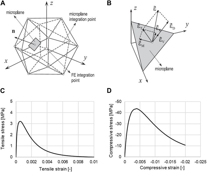
FIGURE 4. (A) Discretization of the unit sphere surrounding the FE integration by 21 integration points (hemisphere). (B) Decomposition of the macroscopic strain vector into microplane strain components—normal (volumetric and deviatoric) and shear. (C) Uniaxial tensile curve for concrete. (D) Uniaxial compressive curve for concrete.
The stress-strain relationships at the microplane level are based on the uniaxial damage theory, suitable for the non-linear analysis of heterogeneous materials, such as concrete and wood (Gambarelli and Ožbolt, 2021; Ožbolt et al., 2022). The initial elastic properties of the material are controlled by the initial elastic modulus (E) and Poisson’s ratio (ν). The exponential damage functions defined for the V-D-T microplane stress-strain relations (Ožbolt et al., 2001) depend on a set of microplane parameters, namely: a, b, p, q for the volumetric compression; e1, m for the volumetric and deviatoric tension; e2, n for the deviatoric compression; e4, k for the two shear components. The adopted elastic (E = 48,000 MPa, ν = 0.2) and microplane parameters (a = 0.003, b = 0.05, p = 0.8, q = 1.5; e1 = 0.00004, e2 = 0.0015, e3 = 0.0011, e4 = 5.0, n = 0.57, n = 0.97, k = 0.65), have been properly calibrated on the single unit size finite element (microplane model) to correctly reproduce the macroscopic elastic and fracture behavior of the C35/45 concrete used in the experiments for the reference beam, as well as for the beam with actuators (configurations M1, R2, U1). The resulting uniaxial tensile and compressive curves are respectively shown in Figures 4C, D. The non-linear material model for concrete was first validated against the reference beam and then used in the beam with actuators for the three configurations reported by Kelleter (2022).
The macroscopic material properties used in the numerical simulations of the present study are summarized in Table 3. It is worth mentioning that a linear elastic behavior was assumed for the actuators (steel S235), while a bilinear elasto-perfectly plastic constitutive law was employed for the reinforcement (B500B) (see Kelleter, 2022).
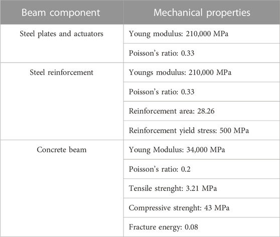
TABLE 3. Material properties.
3.2 Boundary conditions
As mentioned above, only one-quarter of the beam was modeled (see Figure 3), therefore symmetry boundary conditions were imposed in the x-y and y-z plane. The mid-line of the bottom steel plate was fixed in the vertical (y) direction (simply supported beam). The load was applied on the top of the steel plate. The pressure in each actuator was applied on the inner surface of the actuator along the longitudinal axis of the beam. The values of the pressure in each actuator vary according to the configurations discussed in the previous sections.
The geometry of the actuators and the surface area on which the pressure was applied, have a significant impact on the deformational behavior of the beam. As explained by Kelleter (2022), for a realistic evaluation of the pressure applied in the actuators, a pressure leak between the area of the actuator ring and the outer part should be considered. This is related to the fact that the steel sheets of the actuator are welded from the outer edge and possibly the hydraulic oil has leaked into the inner area between the stiffening ring and the outer plate. Therefore, more surface area is available for the pressure application. Figure 5A shows the FE discretization of the actuator and the corresponding deformation is shown in Figure 5B. A 2 mm pressure leak was assumed between inner and outer surface of the actuator, i.e., the effective area for the pressure application corresponds to Din = 78 mm, instead of 70 mm.
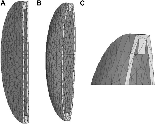
FIGURE 5. (A) Undeformed FE mesh of the actuator. (B) Deformed FE mesh of the actuator. (C) Zoom of the deformed FE mesh of the actuator.
4 Numerical results and comparison with the experiments
The numerical results obtained with microplane material model for the reference beam and the three configurations with actuators (R2, M1, and U1) are discussed in the following section in comparison with the experimental and numerical data by Kelleter (2022).
4.1 Reference beam
The microplane material model is able to correctly reproduce the deformational behavior experimentally obtained for the reference beam. Figure 6A shows the strain distribution along the longitudinal axis of the beam (z direction) with positive strains in the lower part of the beam and negative strains in the upper part, indicating the tensile and compressive zones in the concrete respectively.
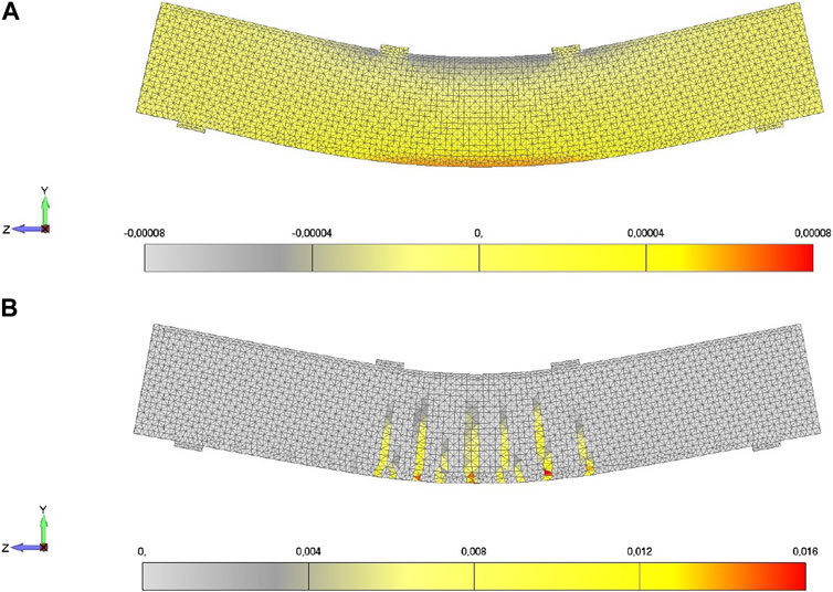
FIGURE 6. Reference beam. (A) Deformed shape-strain contour in z direction. (B) Cracks distribution (maximum principal strains).
The microplane material model with calibrated parameters is able to predict near displacement results. This can be observed in Figure 7 from the load–displacement curve for both the numerical and experimental results, where the displacement of the mid-node of the upper edge of the beam is monitored. The displacement predicted by the microplane material model is −0.0604 mm and the experimental displacement is −0.062 mm. Therefore, the error in the predicted value at the end of the simulation is found to be 2.6%. In the numerical simulation performed by Kelleter (2022), a mid-node displacement of −0.081 mm is obtained, with 23.5% deviation from the experimental result.
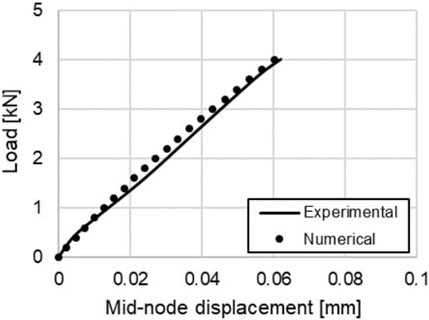
FIGURE 7. Load-displacement curve of the reference beam—experimental vs. numerical.
The maximum strains of the mid-node for the upper (−0.0047%) and lower edge (0.0062%) of the concrete beam are also compared with the experimental results (−0.0049% and 0.0061%). The errors in the strain values are 4.3% for the upper edge and 1.6% for the lower edge. In the numerical simulation by Kelleter (2022) respective strains of −0.006% and 0.0062% are determined, with corresponding errors of 18.3% and 1.6%.
It has to be mentioned, that Kelleter (2022) used the FE model with actuators to calibrate the material model and to simulate the reference beam case. Also, Kelleter (2022) used the isotropic linear elastic constitutive law for concrete and steel in the reference beam case.
As a part of the non-linear analysis, the four-point bending simulation in MASA was continued beyond the 8 kN to observe the cracking behavior of the beam. The resulting damage (cracking) distribution is shown in Figure 6B in terms of maximum principal strains, where the red zone in the legend corresponds to a crack width of 0.1 mm. Similar as in the experiments, the cracks originate in the tension zone of the concrete at a load higher than 35 kN.
4.2 Configuration R2
As reported in Section 2.2.1, in the R2 experimental test a pressure of 5 bar is first applied to the actuators to compensate the self-weight of the concrete beam. A consequent positive displacement of the mid-node in the upper edge of the beam of 0.014 mm is measured in the experiment. Thereafter, the vertical load and the pressure in the actuators are applied simultaneously, according to Section 2.2.1. It is worth mentioning that high scatter in mid-node displacement was obtained in the experiment by Kelleter (2022); therefore, a value of −0.001 mm was here calculated from the experimental displacement profile as average of different points at the end of the test (full load and pressure applied, i.e., adaptive state).
The same as in the experiment, an initial pressure was also applied in the here presented numerical model and the obtained distribution of vertical displacement is shown in Figure 8A. The displacement of the mid-node in the active state in the simulation with the microplane material model is equal to 0.0157 mm. Thereafter, the vertical load and the pressure in the actuators were applied simultaneously in steps of 10 bar, until reaching the maximum load and pressure values specified in section 2.2.1. The obtained results for the adaptive state are shown in Figures 8B, C. It can be seen that the mid-node displacement at the end of the numerical simulation (adaptive state) is equal to −0.025 mm, with deviation of 96.0% with respect to the experiment. In the numerical simulation performed by Kelleter (2022), a mid-node displacement of −0.024 mm is obtained for the adaptive state, with an error of 95.8%.
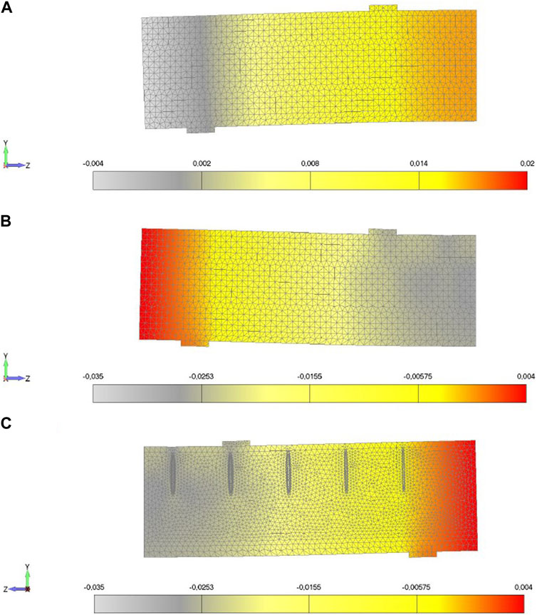
FIGURE 8. Distribution of vertical displacement (deformed shape in milimeters) in R2. (A) Active state. (B) External side in adaptive state. (C) Internal side in adaptive state.
The different lateral expansion of the actuators induced by the different applied pressures is also shown in Figure 8C. The maximum vertical strains of the mid-node for the upper (−0.00206%) and lower edge (0.00649%) of the concrete beam are also compared with the experimental results (−0.00204% and 0.0070%). The error in the strain value is 0.8% for the upper edge and 7.9% for the lower edge. Kelleter (2022) obtained respective strains of −0.002% and 0.0046% in the numerical simulation, with corresponding errors of 2.0% and 52.2% in relation to the experiment.
It has to be pointed out that a more realistic modeling of the steel actuators was adopted in this study by considering also the oil leakage into the inner area between the stiffening ring and the outer plate.
4.3 Configuration M1
The aim of this test was to check the failure of the beam. Therefore, the vertical load and the pressure were significantly increased. It is worth mentioning that an already tested beam was used in the experiments. Therefore, the presence of internal pre-damage cannot be ruled out.
In the numerical simulation with the microplane material model, the first crack was detected at a load of 14.4 kN, whereas in the experiment the first crack was observed at a load of 12.85 kN. The small deviation can be due to the pre-tested beam used in the experiments. The cracks distribution at the end of the numerical simulation with the microplane material model is shown in Figure 9B in terms of maximum principal strains, where the red zone corresponds to a crack width of 0.1 mm. It can be seen that the beam cracked over the entire height in the area of the inner actuators with good agreement with the experimental results (Figure 9A). The cracks localization in the center of the beam is related to the higher pressure of the inner actuators.
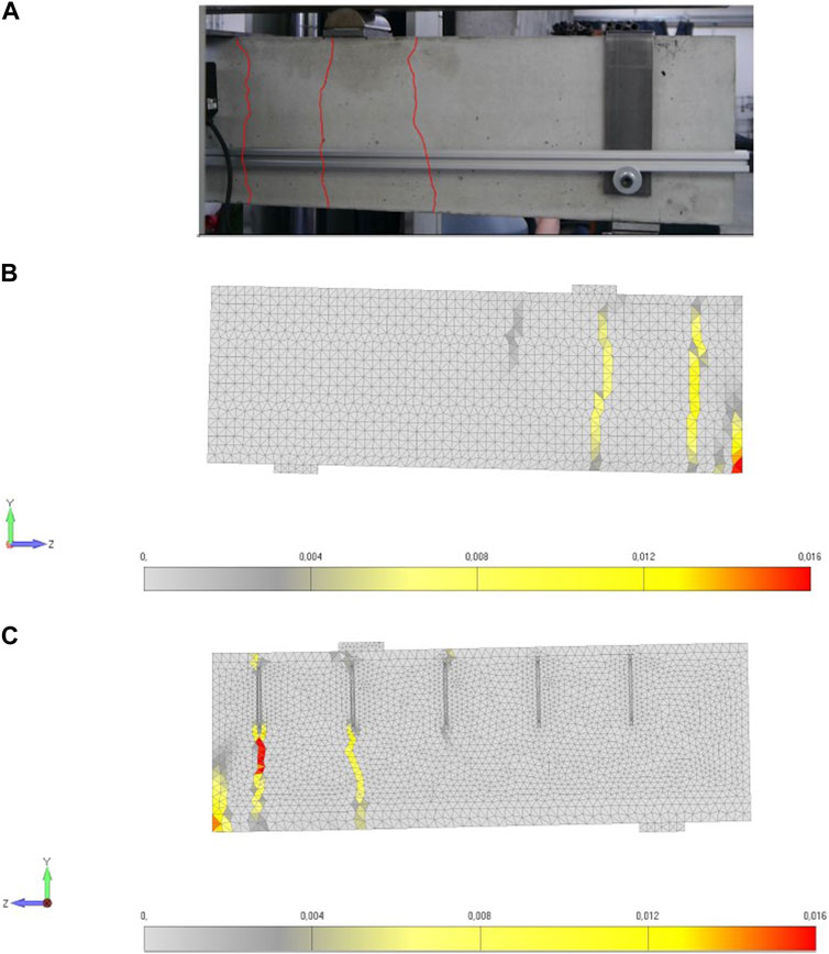
FIGURE 9. Cracking in beam of M1. (A) Experiment [taken from the PhD thesis of Kelleter (2022)]. (B) External side in numerical simulation. (C) Internal section in numerical simulation.
The non-linear numerical simulation was also performed by Kelleter (2022), by using the elasto-plastic damage model in ABAQUS. The cracking pattern obtained with the elasto-plastic damage model is also in agreement with the experimental results. However, no information is provided regarding the load and pressure values at which the first crack forms.
4.4 Configuration U1
As mentioned in the previous sections, in this test equal pressure is gradually applied to each actuator to compensate the passive deflection of the beam. In the experiment, a near zero displacement of the mid-node in the upper edge of the beam (adaptive state) is detected for a pressure value slightly lower than 50 bar. The pressure is then further increased to check the failure of the beam. The first cracks in the outer actuators are detected at a pressure value of 60 bar. Smaller cracks are also visible at the neighboring actuators. The test is stopped at a pressure value of 97 bar.
The numerical simulation with the microplane material model gave a near-zero displacement for the mid-node in the adaptive state for a pressure value in the actuators slightly higher than 80 bar. The vertical displacement distribution in the passive (mid-node displacement of −0.0624 mm) and adaptive state (mid-node displacement of 0.00078 mm) are shown in Figures 10A, B, respectively.
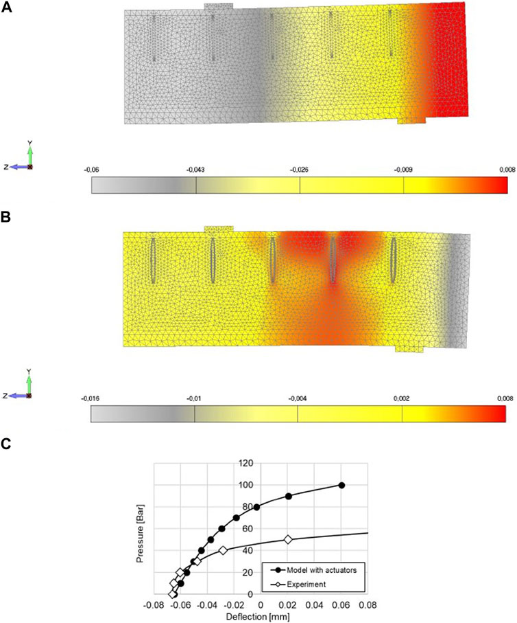
FIGURE 10. Displacements in U1. (A) Distribution of vertical displacement in passive state. (B) Distribution of vertical displacement in adaptive state. (C) Pressure vs. displacement of the mid-node of the upper edge of the beam - numerical vs. experimental.
A comparison between experimental and numerical results in terms of variation of the mid-node deflection with the applied pressure is shown in Figure10C. The significant deviation between the curves can be attributed to different aspects. It is worth mentioning that only one test was performed experimentally, which renders a clear interpretation of the observed trend difficult. One aspect could be pre-damage of the beam due to several reasons, but additional experimental tests are needed to fully clarify the causes for these deviations. Also, in the numerical FE model, the pressure is applied on a surface area of 4775.94 mm2 (diameter 78 mm), by considering 2 mm for the thickness of the actuator. Since the steel sheets are welded from the outer edge, it is difficult to precisely estimate the effective area for the pressure. If less area is considered in the model, higher pressure is required in the numerical analysis to fully compensate the displacement of the mid-node.
Another important aspect for the adaptive behavior of the beam is the stiffness of the actuators. To better understand the influence of the area for the pressure application and the role of the actuators’ stiffness, the actuators were deleted in the model by leaving the corresponding holes within the concrete. As a consequence, the pressure was directly applied to the concrete surfaces with area 5,024 mm2 (diameter 80 mm), corresponding to the external surfaces of the actuators (see Figures 11A, B).
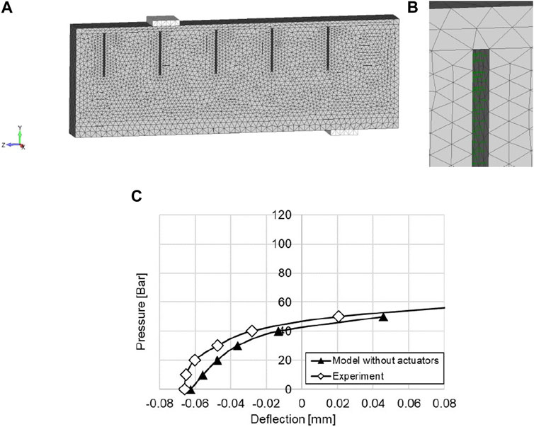
FIGURE 11. Case U1. (A) FE model without actuators and pressure applied to the concrete surface. (B) Detail of the applied pressure. (C) Pressure vs. displacement of the mid-node of the upper edge of the beam - influence of the application area for the pressure.
The new obtained results are shown in Figure 11C against the experimental ones. A better agreement can be observed, confirming the importance of the surface area for the pressure application. Similar to the experiments, a zero mid-node displacement is observed for a pressure value of 50 bar. This result is also consistent with the numerical one obtained by Kelleter et al. (2020) for the same configuration without explicit modeling of the actuators.
In the experiment, the pressure in the actuators was further increased to observe the cracking in the beam (Figure 12A). The obtained numerical crack pattern (model with actuators) is shown in Figure 12B for the front and in Figure 12C for the internal sections, showing a good agreement with the experimental results. It can be seen that the equal pressure in the actuators induces a first cracking in the area of the outer actuators. At the end of the test, the crack goes through the complete height of the beam.
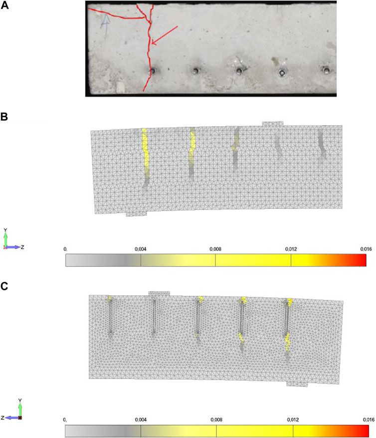
FIGURE 12. Cracks in U1. (A) Cracks distribution in experiment [picture from Kelleter (2022)]. (B) Cracks distribution in the numerical simulation on the external side. (C) Cracks distribution in the numerical simulation on the internal section.
The cracking pattern obtained by Kelleter (2022) for this configuration is also in agreement with the experiment; however, no information is given regarding the load and pressure values at which the first crack forms.
5 Conclusion
In the present study, the adaptive behavior of a concrete beam with integrated fluidic actuators was numerically investigated through 3D FE analysis. The non-linear material model based on the microplane theory (Ožbolt et al., 2001) was used as constitutive law for concrete in the simulations. The model was validated against experimental tests available in the literature and following conclusions can be drawn out: 1) The microplane material model can realistically predict the behavior of the reference beam (without actuators) in terms of load-displacement curve and strains distribution; 2) the adaptive behavior of the beam with actuators (configuration R2) is realistically reproduced in terms of distribution of vertical displacement for both the initial active and the final adaptive state; 3) the model can also capture well the failure of the beam (configuration M1) with realistic cracks patterns; 4) The U1 test is characterized by the most controversial results, showing the importance of a proper modeling of the actuators, their stiffness, and their interaction with the surrounding concrete, including a realistic evaluation of the area of pressure application. Additional experimental tests can be planed in the future to clarify these aspects; 5) also, further studies are necessary to better understand the influence of the geometry of the actuators in concrete structural elements with respect to failure. With this, we plan to investigate placement strategies for actuators balancing compensation and failure risk and for sensors improving the ability to detect failure at an early stage.
Data availability statement
The raw data supporting the conclusion of this article will be made available by the authors, without undue reservation.
Author contributions
SG: Conceptualization, Formal analysis, Investigation, Methodology, Software, Supervision, Validation, Visualization, Writing–review and editing. RF: Conceptualization, Formal analysis, Investigation, Methodology, Validation, Visualization, Writing–review and editing. AS: Investigation, Methodology, Visualization, Writing–original draft. SD: Conceptualization, Writing–review and editing. MB: Supervision, Writing–review and editing. OS: Project administration, Supervision, Writing–review and editing. MN: Resources, Writing–review and editing. LB: Project administration, Supervision, Writing–review and editing.
Funding
The authors declare financial support was received for the research, authorship, and/or publication of this article. The work in this publication was partially funded by the German Research Foundation (DFG—Deutsche Forschungsgemeinschaft, Project-ID 279064222) as part of the Collaborative Research Centre 1244 (SFB 1244) Adaptive Skins and Structures for the Built Environment of Tomorrow, project B04, C02. This publication was funded by the German Research Foundation (DFG) grant “Open Access Publication Funding/2023–2024/University of Stuttgart” (512689491).
Conflict of interest
The authors declare that the research was conducted in the absence of any commercial or financial relationships that could be construed as a potential conflict of interest.
Publisher’s note
All claims expressed in this article are solely those of the authors and do not necessarily represent those of their affiliated organizations, or those of the publisher, the editors and the reviewers. Any product that may be evaluated in this article, or claim that may be made by its manufacturer, is not guaranteed or endorsed by the publisher.
References
Bažant, Z., and Oh, B. (1983). Crack band theory for fracture of concrete. Matériaux Constr. 16, 155–177. doi:10.1007/BF02486267
Burghardt, T., Kelleter, C., Bosch, M., Nitzlader, M., Bachmann, M., Binz, H., et al. (2022). Investigation of a large-scale adaptive concrete beam with integrated fluidic actuators. Civ. Eng. Des. 4, 35–42. doi:10.1002/cend.202100037
Gambarelli, S., and Ožbolt, J. (2021). 3d hygro-mechanical meso-scale model for wood. Constr. Build. Mater. 311, 125283. doi:10.1016/j.conbuildmat.2021.125283
Geiger, F., Gade, J., von Scheven, M., and Bischoff, M. (2020). A case study on design and optimization of adaptive civil structures. Front. Built Environ. 6. doi:10.3389/fbuil.2020.00094
Heidingsfeld, M., Rapp, P., Böhm, M., and Sawodny, O. (2017). “Gramian-based actuator placement with spillover reduction for active damping of adaptive structures,” in 2017 IEEE international conference on advanced intelligent mechatronics (AIM), 904–909. doi:10.1109/AIM.2017.8014133
Hillerborg, A., Modéer, M., and Petersson, P.-E. (1976). Analysis of crack formation and crack growth in concrete by means of fracture mechanics and finite elements. Cem. Concr. Res. 6, 773–781. doi:10.1016/0008-8846(76)90007-7
Ibrahimbegovic, A., Boulkertous, A., Davenne, L., and Brancherie, D. (2010). Modelling of reinforced-concrete structures providing crack-spacing based on x-fem, ed-fem and novel operator split solution procedure. Int. J. Numer. Methods Eng. 83, 452–481. doi:10.1002/nme.2838
Jason, L., Torre-Casanova, A., Davenne, L., and Pinelli, X. (2013). Cracking behavior of reinforced concrete beams: experiment and simulations on the numerical influence of the steel-concrete bond. Int. J. Fract. 180, 243–260. doi:10.1007/s10704-013-9815-6
Kelleter, C., Burghardt, T., Binz, H., Blandini, L., and Sobek, W. (2020). Adaptive concrete beams equipped with integrated fluidic actuators. Front. Built Environ. 6. doi:10.3389/fbuil.2020.00091
Kelleter, C. (2022). Untersuchungen zur Manipulation des Lastabtrages biegebeanspruchter Betonbauteile durch integrierte fluidische Aktoren. Ph.D. thesis. doi:10.18419/opus-12236
Nitzlader, M., Steffen, S., Bosch, M. J., Binz, H., Kreimeyer, M., and Blandini, L. (2022). Designing actuation concepts for adaptive slabs with integrated fluidic actuators using influence matrices. CivilEng 3, 809–830. doi:10.3390/civileng3030047
Ožbolt, J., Gambarelli, S., and Zadran, S. (2022). Coupled hygro-mechanical meso-scale analysis of long-term creep and shrinkage of concrete cylinder. Eng. Struct. 262, 114332. doi:10.1016/j.engstruct.2022.114332
Ožbolt, J., Li, Y., and Kožar, I. (2001). Microplane model for concrete with relaxed kinematic constraint. Int. J. Solids Struct. 38, 2683–2711. doi:10.1016/S0020-7683(00)00177-3
Reksowardojo, A. P., Senatore, G., Srivastava, A., Carroll, C., and Smith, I. F. (2022). Design and testing of a low-energy and -carbon prototype structure that adapts to loading through shape morphing. Int. J. Solids Struct. 252, 111629. doi:10.1016/j.ijsolstr.2022.111629
Senatore, G., and Reksowardojo, A. P. (2020). Force and shape control strategies for minimum energy adaptive structures. Front. Built Environ. 6. doi:10.3389/fbuil.2020.00105
Sobek, W., Sawodny, O., Bischoff, M., Blandini, L., Böhm, M., Haase, W., et al. (2021). Adaptive hüllen und strukturen. Bautechnik 98, 208–221. doi:10.1002/bate.202000107
Stiefelmaier, J., Böhm, M., Sawodney, O., and Tarin, C. (2023). Parity space-based fault diagnosis in piecewise linear systems (international federation of automation control world congress).
Stiefelmaier, J., Gienger, A., Böhm, M., Sawodny, O., and Tarin, C. (2022). A bayesian approach to fault diagnosability analysis in adaptive structures. IFAC-PapersOnLine 55, 347–352. doi:10.1016/j.ifacol.2022.10.537
United Nations Environment Programme (2020). Global status report for buildings and construction: towards a zero-emission, efficient and resilient buildings and construction sector. Tech. rep.
Wagner, J. L., Gade, J., Heidingsfeld, M., Geiger, F., von Scheven, M., Böhm, M., et al. (2018). On steady-state disturbance compensability for actuator placement in adaptive structures. A. T. - Autom. 66, 591–603. doi:10.1515/auto-2017-0099
Keywords: adaptivity, concrete, numerical simulations, finite element method, microplane material model, cracking
Citation: Gambarelli S, Fararoni Platas RN, Shankar A, Dakova S, Böhm M, Sawodny O, Nitzlader M and Blandini L (2023) Failure behavior of an adaptive concrete beam with integrated fluidic actuators: non-linear three-dimensional finite element analysis. Front. Built Environ. 9:1272785. doi: 10.3389/fbuil.2023.1272785
Received: 04 August 2023; Accepted: 27 September 2023;
Published: 10 October 2023.
Edited by:
Elena Benvenuti, University of Ferrara, ItalyReviewed by:
Radomír Pukl, Cervenka Consulting, CzechiaRoberto Fedele, Polytechnic University of Milan, Italy
Stefano Mariani, Polytechnic University of Milan, Italy
Copyright © 2023 Gambarelli, Fararoni Platas, Shankar, Dakova, Böhm, Sawodny, Nitzlader and Blandini. This is an open-access article distributed under the terms of the Creative Commons Attribution License (CC BY). The use, distribution or reproduction in other forums is permitted, provided the original author(s) and the copyright owner(s) are credited and that the original publication in this journal is cited, in accordance with accepted academic practice. No use, distribution or reproduction is permitted which does not comply with these terms.
*Correspondence: Serena Gambarelli, c2VyZW5hLmdhbWJhcmVsbGlAbXBhLnVuaS1zdHV0dGdhcnQuZGU=