 Xue-hui Ge
 Nanjie Wei1,2
 Ling Li
- 1Engineering Research Center of Reactive Distillation, Fujian Province Higher Education Institutes, College of Chemical Engineering, Fuzhou University, Fuzhou, Fujian, China
- 2Qingyuan Innovation Laboratory, Quanzhou, Fujian, China
An integrated microfluidic planar reactor is essential for achieving efficient and enhanced photocatalytic water treatment. Optimization of catalysts is an area of intense study owing to the need to enhance the performances of microreactors. A high-efficiency photocatalytic microreactor is presented here by combining a planar microreactor with a high-efficiency photocatalyst. TiO2 nanoparticles doped with Y and Yb were prepared to improve the photocatalytic reaction efficiency. First, better performance is achieved with the Y, Yb/TiO2 and TiO2 microreactors than conventional bulk reactors because of good photodegradation and a high reaction rate. Then, the Y, Yb/TiO2 film microreactor exhibits not only efficient catalytic activity with UV light but also higher photocatalytic activity under visible light irradiation than that achieved by a TiO2 film microreactor. The reaction rate constant of the Y, Yb/TiO2 film microreactor is approximately 0.530 s–1, which is twice that of the TiO2 film microreactor. Moreover, the performances under continuous and intermittent reactions are compared to evaluate the stability of the microreactor, thereby building the foundation for practical application of continuous water treatment in the microreactor.The planar microreactor provides a convenient platform for studying photodegradation under various conditions, such as different temperatures, flow rates, light irradiation (UV and Vis), and reaction modes (continuous and intermittent).
1 Introduction
According to the World Health Organization (WHO), approximately 844 million people worldwide lack any form of clean drinking water, and approximately 159 million rely on water from surface water sources (Organization WHJGWHO, 2017). Photocatalysis is the process of converting light energy to synthesize or degrade compounds. Photocatalytic reaction is a clean and environmentally friendly green chemistry and is essentially a REDOX reaction (Fujishima and Zhang, 2006). In the late 1970s, the semiconductor TiO2 was first used as a photocatalyst for cyanide degradation (Frank and Bard, 1977); later, the dechlorination degradation of PCBS by TiO2 under 365 nm light has also been verified (Fernández-Catalá et al., 2019). Since then, photocatalytic technology has developed rapidly for water treatment, and research and applications of the environmentally friendly photocatalytic technology are increasing day by day (Wang et al., 1997).
To reduce the influence of the mass transfer limitation on photocatalysis, a reasonably designed reactor or reaction system is vital. According to the distribution state of the photocatalyst, the reactor can be divided into two main types as follows: 1) slurry reactor in which the catalyst particles are suspended in liquid phase to form a slurry; although this has a rapid mass transfer capacity, the suspended solid catalyst will cause uneven distribution of the incident light, which will reduce the photon transmission rate of the entire system, and the separation and recovery of the suspended catalyst particles will also increase the operational difficulty. 2) Fixed reactor in which the catalyst is immobilized in the form of a thin film coating; this reactor has good photon transfer efficiency, but a low specific surface area will lead to slow mass transfer.
Microfluidic optics plays a positive role in promoting the development and application of photocatalytic water treatment technologies. Microfluidic optics is a new interdisciplinary subject that integrates fine machining, materials, optics, hydrodynamics, and other disciplines (Liu et al., 2008; Dündar et al., 2010; Ooms and Sinton, 2012; Dong et al., 2014; Liu and Lee, 2014; Ravi et al., 2014). A microfluidic reactor has the advantages of high mass transfer and heat transfer. Its inherent large specific surface area and reaction volume can greatly improve the photon and mass transfer efficiencies while effectively realizing photocatalytic reaction enhancement (Gerven et al., 2007; Dündar et al., 2010; Su et al., 2015; Min et al., 2017; Azzouz et al., 2018; Huang et al., 2018; Fernández-Catalá et al., 2019). The utilization rate of the catalyst can be improved effectively when the catalyst is fixed on a suitable substrate (Bahnemann, 2004; Li et al., 2013; Liu, 2016).
A photocatalytic microfluidic reactor refers to a reactor with at least one of the length, width, and height dimensions being less than 1 mm. The microfluidic photocatalytic apparatus has high heat and mass transfer efficiencies, which can effectively overcome the limitations of the photon and mass transfer efficiencies in traditional photocatalytic converters to promote photocatalytic water treatment reactions (Liu et al., 2008; Dong et al., 2013; Dong et al., 2014; He et al., 2016).
Azzouz et al. (2018) first designed the structure of the microreactor with a multistage tree channel design at the inlet and outlet, with a parallel groove design at the bottom of the reaction chamber to increase the support area of the catalyst. However, this was accompanied by problems such as difficulty in separating the catalyst from the product. Yu and Wang (2020) designed a three-phase photocatalytic microreactor that can stably and accurately control the gas–liquid–solid interface; this microreactor generates periodic bubbles in the running microflow, resulting in a strong and complex three-phase mixed flow that accelerates the catalytic reaction process due to enhanced mass transfer efficiency. However, because of the introduction of the three-phase system, the experimental operation is more complicated.
Some research teams have also optimized the catalysts for microreactors. Lin (Liu, 2016) used chemical etching and sol-gel technology to prepare a planar photocatalytic microreactor with Cu2+ and La3+ metal-ion-doped TiO2 coating to study the degradation of methylene blue under ultraviolet radiation, visible light, and sunlight. Jia et al. (2019) reported a microfluidic reactor using gold nanoparticles (AuNPs) to efficiently photocatalyze the degradation of organic pollutants under visible light; TiO2/AuNP films have strong absorption capacities above 400–800 nm, but their photodegradation ability under ultraviolet conditions has not been discussed.
Wang et al. (2012) carried out external field strengthening outside the microreactor by designing the top and bottom parts of the reaction chamber using ITO conductive glass and conducted photodecomposition by changing the voltage polarity while controlling the electron-driven or hole-driven oxidation. However, the addition of an electric field greatly increased the energy consumption in their study.
The problems that have not been discussed above or noted for microchannel reactors are considered herein. In this paper, a planar photocatalytic microfluidic reactor with a 5-level tree-shaped microchannel and 12 mm × 12 mm reaction chamber was designed for light photocatalysis of water. The Y, Yb/TiO2 nanoparticles were bonded to the bottom substrate as the catalysts. The catalytic performance of the microreactor for photodegradation was studied by changing the concentrations and flow rates of the reactants as well as reaction temperature and illumination conditions. In particular, to investigate the potential applications of the reactor in industry, the degradation performances of the microreactor were researched and compared in terms of batch and continuous reactors over a long period of time. The results show that through doping optimization of the Y/Yb rare-earth ions, the degradation performance of the microreactor under visible light was improved greatly and that the microreactor maintained good degradation effects during continuous operation.
2 Experiments
2.1 Structure of the planar microreactor
The structure of the microreactor used in this study is shown in Figure 1; it has a 5-level tree-shaped microchannel and comprises a PDMS plate as the cover and glass slides as the substrates. The microchannel and thin film are fixed in the middle of the microreactor to form a square reaction chamber of volume 7.2 μL (12 mm × 12 mm × 50 μm). The glass substrate is coated with the Y, Yb/TiO2 film (5 μm thick), which covers the entire reaction chamber. Preparations for the porous TiO2 film experiment are shown in Supplementary Figure S1. The tree-branch-shaped microchannels are used to uniformly distribute the solution throughout the reaction chamber so as to achieve maximum contact with the film.
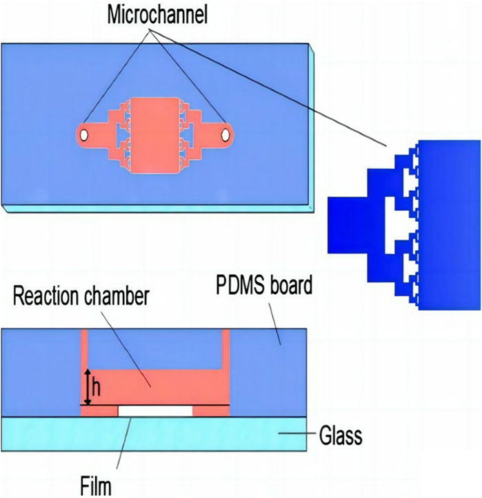
Figure 1. Schematic illustration and cross-sectional view of the microreactor.
2.2 Materials and instruments
P25 anatase TiO2, methylene blue (MB) reagent, acetylacetone, Triton X-100, and polyethylene glycol-2000 were purchased from Aladdin. Y(NO3)3·6H2O and Yb (NO3)3·6H2O were purchased from Chemical Reagent Co. Except for the MB reagent, all other chemical reagents were analytically pure. MB solutions of different concentrations were prepared in this study by dissolving in deionized water.
The synthesized Y, Yb/TiO2 nanoparticles were characterized by scanning electron microscopy (SEM, Thermo Fisher Scientific, Helios G4 CX), X-ray diffraction (XRD, Rigaku, MiniFlex 600), X-ray photoelectron spectroscopy (XPS, Thermo Fisher Scientific, ESCALAB 250), and UV-visible diffuse reflectance spectroscopy (UV-vis DRS, Agilent, Cary 7000). The absorption spectra between the original and degraded MB solutions were analyzed using a UV-vis spectrophotometer (Beifen-Ruili UV-2601).
Some of the main characterizations are achieved through setting the appropriate experimental parameters. The XRD parameters are as follows: Cu target, Kα ray, angle 10°–80°, and scattering slit 1°. The UV-vis instrument parameters are as follows: wavelength 200–800 nm, wavelength accuracy ≤ ±0.08 nm, and photometric accuracy ±0.00025 A.
2.3 Efficiency test for photocatalytic degradation
The photocatalytic microfluidic system consists of five parts: the syringe pump, light source, collection bottle, temperature controller, and planar microreactor, as shown in Figure 2. The fluid volumes and flow rates are controlled precisely using the syringe pump. The planar microreactor connects with the syringe pump and collector via pipes. The light source is placed 10 cm directly above the microreactor to provide uniform light. The temperature controller maintains the reaction temperature. All components except the microreactor are set so as to avoid light exposure.
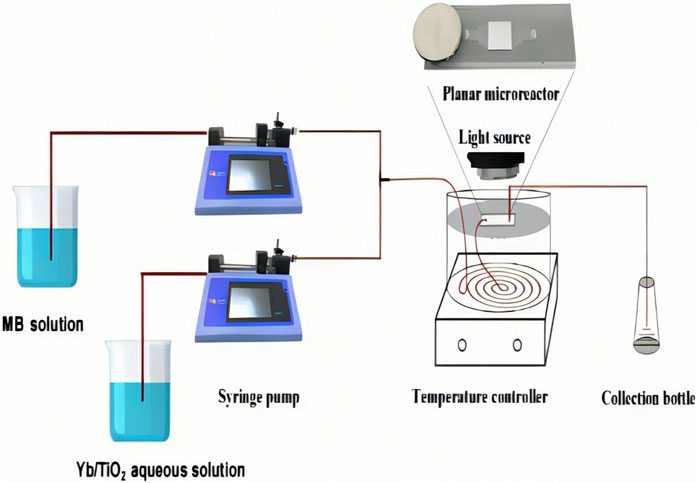
Figure 2. Device diagram of the photocatalytic microfluidic system.
In the photocatalytic microfluidic system, the flow rate and MB solution concentration are the major factors affecting the photocatalytic reaction efficiency. The solutions are pumped at 33, 42, 55, 83, and 167 μL/min to investigate the flow rate effects in different planar microreactors. The initial concentrations of the MB solution are maintained at 3 × 10⁻⁵, 4 × 10⁻⁵, and 5 × 10⁻⁵ mol/L. The photocatalytic experimental parameters of the planar microreactor are shown in Table 1.

Table 1. Parameters of the photocatalytic experiments on planar microreactors.
The aqueous MB solution was introduced into the microreactor through the syringe pump that also controls the reaction flow rate, and degradation was carried out under 15 mW/cm2 of ultraviolet light (<390 nm) and visible light (390–770 nm). After a single set of reactions, the samples were retrieved from the collection bottle at the end of the system for detection.
To investigate the potential applications of the reactor in industry, the microreactor was designed to be used both in batch and continuous reactor modes for a long period of time. In the batch mode, the reaction stops, and the microreactor resets after each 5-mL sample generation. The reset procedure means that the microreactor is washed with deionized water at a flow rate of 50 μL/min for 5 min and that the light is maintained to remove any residual MB solution in the microfluidic system.
As a In the continuous mode, the reaction is continuous, and reactor is not cleaned at intervals. After every 5 mL of sample generation, the degradation products were retrieved for absorbance detection in each set of reactions. After each sampling, the reaction continued in the continuous reaction mode.
2.4 Degradation performance of photocatalytic planar microreactor
For data analyses, the degradation and reaction rate constants can be calculated from the concentration data of MB through the following relationships (Meng et al., 2013; Lamberti, 2015):
where k is the reaction rate constant, t is the effective residence time, C0 and C represent the initial concentration and the concentration after degradation, respectively, and x is the photocatalytic degradation rate. The microreactor system shows continuous and intermittent reactions during research progress.
The microreactors for the batch reactions that were cleaned using deionized water and ethanol after each reaction (approximately 15–150 min) were defined as the intermittent planar microreactors (IPRs), and the microreactors for continuous reactions (>12 h) that were not cleaned at intervals were defined as continuous planar microreactors (CPRs).
3 Results and discussion
3.1 Characterization and analysis of photocatalyst
The apparent morphology of Y, Yb/TiO2 cross-sectional morphology of the catalyst film, and qualitative analysis of the electron probe attached to the scanning electron microscope by an energy spectrometer are shown in Supplementary Figure S2. The 5-μm catalyst film shows good uniformity as a whole and has a loose structure and micropores in the depth direction.
The phase compositions and valences of the samples were characterized by XRD and XPS, as shown in Figure 3. The diffraction peaks agree well with those of the pure anatase TiO2 according to JCPDS card no. 21–1272, as shown in Figure 3A. This shows that the synthesized Y, Yb/TiO2 has a pure anatase phase.
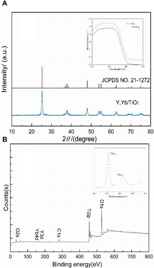
Figure 3. (A) XRD and UV-vis DRS pattern and (B) XPS results of the synthetic nanosized Y, Yb/TiO2.
The optical absorption of the catalyst is a critical factor for photoreactivity (Dong et al., 2016). The DRS characterization spectrum of the sample in the UV-vis region is expressed in Figure 3A. After doping with elemental Y and Yb, the absorption band of TiO2 shifts to the infrared region. The bandgap of TiO2 doped with Y and Yb becomes narrower, and Y, Yb/TiO2 shows enhanced photon absorption effect in the spectral range of 390–800 nm. Therefore, an expansion in the absorption wavelength range of the incident photons can promote photocatalytic performance.
The highly symmetric shapes of the titanium XPS lines in Figure 3B suggest that titanium is present only as Ti4+. In fact, the presence of titanium with any oxidation state lower than +4 should have been evidenced by the presence of shoulders on the binding energy sides of the peaks, which was not observed. Because the radii of the Y and Ti atoms are similar, it is easier for the Y atoms to enter the catalyst lattice. There is one electron missing in the crystal lattice, which generates oxygen vacancies to balance the overall electron composition. The fresh oxygen vacancies are bound to titanium dioxide, so the remaining O atoms move to form additional energy levels to narrow the bandgap transitions of the titanium dioxide electrons conveniently to realize effective broadening of the spectral absorption range.
3.2 Degradation performance of the photocatalytic planar microreactor
3.2.1 The photodegradation effect of IPR
The photodegradation rates shown in Figure 4 represent the average values from three or more experiments, with error bars. The control experiments exclude the self-degradation interference of MB under the same conditions. The values show that the microreactor has excellent degradation effects for MB under UV light. Under different flow rates, the UV-catalyzed degradations of the microreactors including Y, Yb/TiO2, and TiO2 IPRs are better than those of the bulk reactors. Complete degradation can be achieved in the IPR when the reaction time exceeds 90 min. Compared with the TiO2 IPR, the Yb, Y/TiO2 IPR shows better degradation performance.
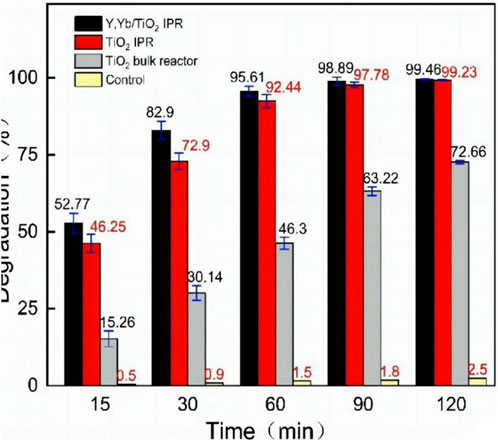
Figure 4. Photodegradation degrees (%) of MB solution (C0 = 4 × 10⁻⁵ mol/L) in different reactors under UV irradiation.
Cycling tests were performed on the Y, Yb/TiO2 and TiO2 IPRs at different flow rates to measure their stability after multiple experiments. Six consecutive experiments were performed with different flow rates and no cleaning, and the absorbance of a 5-mL sample of the degradation product was detected by a single reaction. The initial concentration of the MB solution was 5 × 10⁻⁵ mol/L, and the flow rates were 55, 83, and 167 μL/min at total reaction times of 540, 360, and 180 min, respectively. The result shown in Figure 5 indicates that the two microreactors have similar trends and that both have better stabilities at lower flow rates. When the flow rate is below 55 μL/min, the catalytic degradation of MB is almost complete after flowing through the channel, and the degradation rates of both the IPRs are stable. At higher flow rates, the stabilities of the microreactors decrease after several experiments. The reason for this is that when the solution flows through the microreactor, a high flow rate leads to deposition of the pigment, which in turn affects the degradation efficiency. Moreover, the stability of the Y, Yb/TiO2 IPR is slightly better than that of the TiO2 IPR.
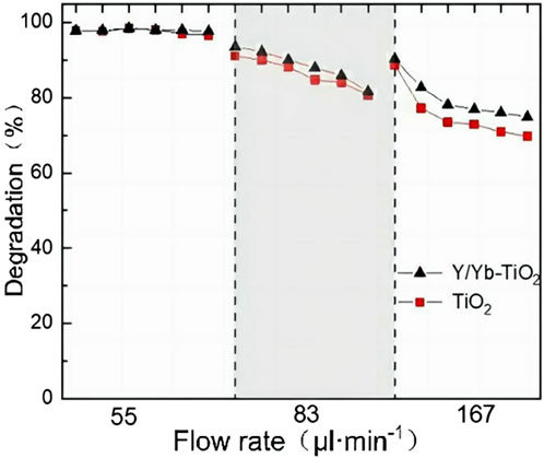
Figure 5. Continuous stability experiments of the microreactors.
To explore the reasons for the decrease in stability, the velocity field distribution simulation of the reactor was carried out, as shown in Supplementary Figures S3, S4. The velocity field distribution simulation of the microreactor at 55 μL/min is shown in Figure 6. The velocity at the microchannel edges is relatively lower than that at the center. This dramatic velocity gradient between the central part and edges causes a concentration difference in the microchannel. At the same time, the light source used in the photocatalytic reaction has a certain exothermic phenomenon, which leads to adhesion of the organic reactants with PDMS and some residues. Therefore, dead zones can easily form at corners and cause reactant residue problems, resulting in MB pigment retention at the corners, which further affects the stability of the microreactor, as illustrated in the top left image of Figure 6.
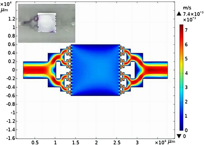
Figure 6. Simulation results of the velocity field of the microreactor at 55 μL/min. The inset figure shows the condition of the planar microreactor after continuous reaction over 12 h.
3.2.2 The photodegradation effect of CPR
The continuous degradation performances of the TiO2 CPR and Y, Yb/TiO2 CPR at different flow rates were investigated, as shown in Figure 7. The experiment was designed to be performed under UV light at reactant concentrations of 9.6, 12.8, and 16.0 ppm. The results showed that the degradation of MB by Y, Yb/TiO2 CPR remained good at low concentrations and low flow rates, with trends similar to those of the TiO2 CPR. However, the overall degradation effect of the Y, Yb/TiO2 CPR is better than that of the TiO2 CPR, especially at low concentrations or low flow rates. When the experimental condition was 16.0 ppm at 33 μL/min, the degradation rate was 19.5% higher than that of the TiO2 CPR; a comparison of the experimental results further verified that Y/Yb doping optimized TiO2 and improved its catalytic performance under UV light.
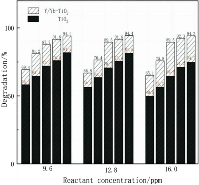
Figure 7. Contrast experiments of photocatalysis by the Y, Yb/TiO2 CPR and TiO2 CPR under UV light. The flow rates are 33, 42, 55, 83, and 167 μL/min from right to left at each reactant concentration.
Furthermore, the degradation effects of the Y, Yb/TiO2 CPR were explored under different light conditions, as shown in Figure 8, where the photocatalytic degradation rate was obtained from formula 1. The yellow columnar strip is the degradation rate under visible light (390–770 nm), and the white diagonal strip is the degradation rate under UV light (<390 nm). Under visible light, the photodegradation effect of the Y, Yb/TiO2 CPR is lower than that under UV light. At low flow rates, the change in degradation rate caused by different light conditions is more obvious. For example, at a flow rate of 55 μL/min, when the concentration is 16.0 ppm, the degradation rate under UV light is 20% higher than that under visible light. However, the degradation rate of the Y, Yb/TiO2 CPR under visible light is still better than that of the TiO2 CPR under UV light, as seen by comparing Figures 7, 8. Therefore, the broadening in the spectral absorption range by doping rare-earth ions into TiO2 could still be an effective method to strengthen the photocatalytic degradation reaction.
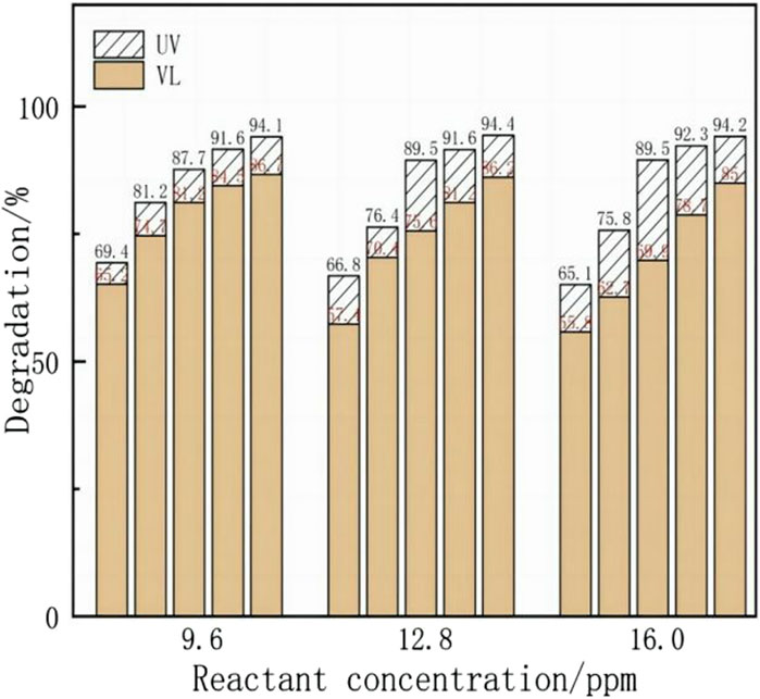
Figure 8. Y, Yb/TiO2 CPR photocatalytic experiments under different illumination, with flow rates of 33, 42, 55, 83, and 167 μL/min from right to left at each reactant concentration.
3.3 Degradation performance comparison
For an overall comparison of different reactors, Figure 9A plots the reaction rate constant, which is derived from formula 2. The reaction rate constants under UV light are compared, where the slope represents the degradation rate. The analytical data points are the experimental averaged values. A linear fit of the tested data for the contrast experiment shows that the bulk reaction yields k = 0.0109 min−1. The Y, Yb/TiO2 IPR yields k = 0.586 s−1, which is nearly two times higher than that of other reported microfluidic reactors (Li et al., 2018) (Figure 9B) and more than that of the TiO2 IPR in this work. Both IPRs show more efficient degradation performances than the bulk reactors, and the reaction rate constants are higher by at least two orders of magnitude. In the CPR, the degradation of the TiO2 film decreases by more than 60% in the presence of attached reactant residue problems. The reaction rate constant of the Y, Yb/TiO2 CPR is calculated as 0.290 s−1, which is almost two times that of the TiO2 CPR. These results show that the Y, Yb/TiO2 film is more efficient and stable. Compared with the bulk reactor, both the IPR and CPR have better degradation efficiencies, but the CPR’s degradation efficiency is lower than that of the IPR, especially at high flow rates. This is because in the continuous high-flow-rate degradation process, the difference in flow rates between the central and edge areas of the microreactor leads to the formation of dead zones at corners, resulting in reactant residues that affect the IPR’s degradation efficiency.
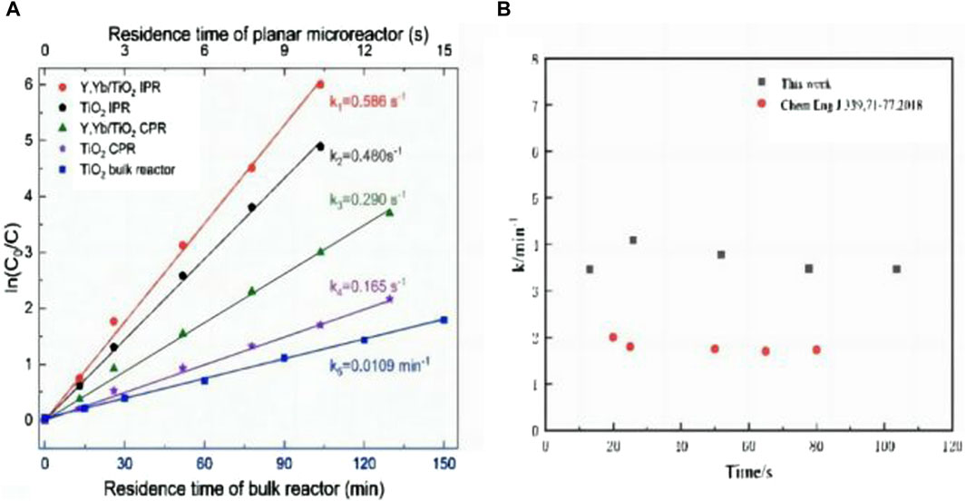
Figure 9. (A) Degradations of the MB solution in different planar microreactors as functions of residence time under UV light. (B) Reaction rate constants of other photocatalytic microfluidic reactors.
The degradation rates of the MB solution by Y, Yb/TiO2 and TiO2 under UV and visible irradiation with different flow rates in the CPR are shown in Figure 10A. The degradation rates decrease obviously as the flow rates increase. The photocatalytic degradation effect of Y, Yb/TiO2 on MB solution under visible light is lower than that under UV light but higher than that of TiO2 under UV irradiation. This difference in degradation under UV and visible light is influenced by the range of spectral absorption of the Y, Yb/TiO2 nanoparticles. It is confirmed that enhancement of Y, Yb/TiO2 photodegradation exists in both the continuous and intermittent reactions. Therefore, TiO2 doping of Y, Yb to expand the light response range is an effective method of achieving enhanced photocatalytic effects in materials research.
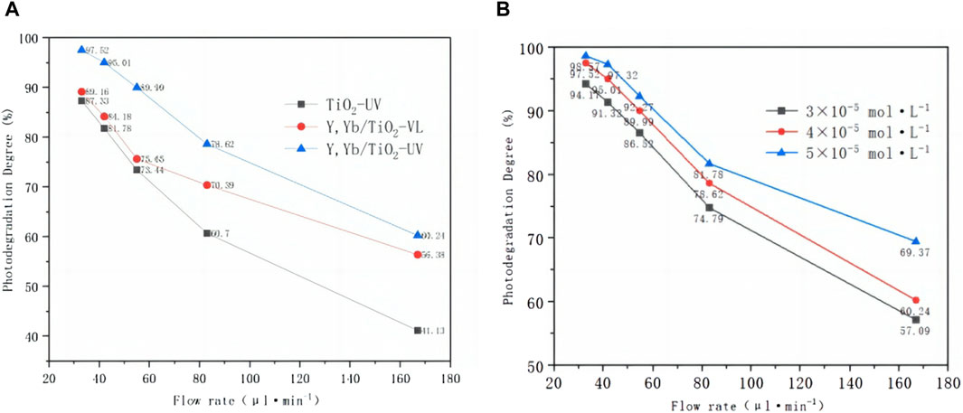
Figure 10. (A) Photodegradation degrees (%) of the MB solution with Y, Yb/TiO2 CPR and TiO2 CPR under UV and visible light irradiation for different flow rates. (B) Photodegradation degrees (%) with the Y, Yb/TiO2 CPR for different MB solution concentrations.
The influence of the concentration of the MB solution on the Y, Yb/TiO2 CPR is analyzed in Figure 10B. The degradation effect is better at low flow rates considering first-order kinetic factors, but the initial concentration has a certain effect on the photodegradation efficiency. With the increase in the initial concentrations of the reactants, the photodegradation efficiency increases, but the overall effect is not large. When the flow rate increases to 167 μL/min, the overall degradation rate decreases, and there are marked differences in photodegradation between different concentrations. The photodegradation degree is 69.37% at C0 = 3 × 10⁻⁵ mol/L and increases further at C0 = 5 × 10⁻⁵ mol/L. Through fitting the reaction rate constant at different concentrations, the value of k is found to be similar.
3.4 Effects of temperature and H2O2 addition on microreactor performance
The performances for photocatalytic degradations of the MB solution at 5, 25, and 50°C are shown in Figure 11; it is seen that the reaction rate increases with the increase in time and temperature. When the flow rate is high, the degradation performance of the MB solution at 50°C is more efficient than that at 5 or 25°C because of the increase in the catalyst activity at a suitably high temperature. The effects of the reaction temperature mainly influence the quantum effects, i.e., electron–hole separation and recombination (Chen and Hsu, 2021). Moreover, the diffusion of MB and its reaction products increased with the increase in temperature, and the mass transfer limit was weakened further.
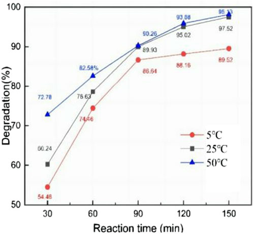
Figure 11. Influence of temperature in the continuous microreactor at different reaction times.
In bulk reactors, H2O2 with strong photocatalytic activity is generally used to enhance the photodegradation effect. The UV degradation experiment for 12.8 ppm MB was carried out to explore the effect of addition of H2O2 on the Y, Yb/TiO2 CPR, as shown in Figure 12. However, it is seen that the decrease in degradation rate may be due to the effect of scavengers. The scavenger effect refers to the fact that during photocatalysis, some substances (often referred to as scavengers) may react with the generated reactive oxygen species, thereby slowing or hindering effective reaction between the oxygen radicals and target pollutants (Múčka et al., 2013). As an oxidation scavenger, H2O2 neutralizes the activities of hydrogen- and oxygen free radicals by trapping them. This trapping effect can make the hydroxyl radicals lose their ability to react, thus slowing the degradation reaction in the photocatalytic process and reducing the photodegradation performance of MB.
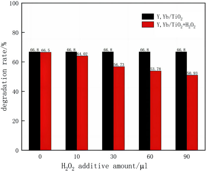
Figure 12. Effects of H2O2 on the Y, Yb/TiO2 CPR.
4 Conclusion
A high-efficiency photocatalytic microreactor was developed by combining a planar microreactor and high-efficiency photocatalyst. TiO2 nanoparticles doped with Y and Yb were prepared to improve the photocatalytic reaction efficiency for efficient treatment of organic wastewater. The microreactor demonstrated superior photodegradation effects and higher reaction rates compared to bulk reactors. The degradation performances of the microreactor were studied for extended periods of continuous operation, with comparison of the IPR and CPR to assess the practicality of the microreactor. The results showed that under high flow rates, the IPR was more effective than the CPR due to the formation of dead zones at the central and edge areas of the reactor under large flow rate differences, which resulted in accumulation of reactant residue at the corners and ultimately hindered degradation. Conversely, at low flow rates, the IPR and CPR yielded similar effects owing to the small flow rate difference between the central and edge areas, leading to less reactant residues at the corners. Furthermore, the photocatalytic properties of TiO2 and Y/Yb-doped TiO2 microreactors were studied, and the results showed that the Y/Yb-doped TiO2 microreactor displayed good degradability and stability. The UV degradation performance of the Y/Yb-doped TiO2 reactor was superior to that of TiO2, while also displaying improved degradation under visible light for MB. The reaction rate constant of the Y/Yb-doped TiO2 CPR was approximately 0.530 s−1, which was double that of the TiO2 CPR, indicating significantly improved system stability over long periods of operation. Overall, rare-earth-ion doping optimization can significantly improve the degradation performance of a microreactor under visible light while also maintaining good degradation effects during continuous operation.
Data availability statement
The original contributions presented in the study are included in the article/Supplementary Material; further inquiries can be directed to the corresponding authors.
Author contributions
X-hG: conceptualization, formal analysis, funding acquisition, methodology, project administration, resources, writing–original draft, and writing–review and editing. NW: data curation, formal analysis, writing–original draft, and writing–review and editing. XH: data curation, formal analysis, and writing–original draft. QX: data curation, formal analysis, and writing–original draft. XW: conceptualization, project administration, methodology, and writing–original draft. LL: project administration, supervision, validation, and writing–review and editing. TQ: resources, software, supervision, validation, visualization, and writing–review and editing.
Funding
The author(s) declare that financial support was received for the research, authorship, and/or publication of this article. This work was supported by the National Natural Science Foundation of China (Grant Nos 22378059 and 22378067), the Fujian Province Science and Technology Guidance Project (Grant No. 2021Y0007), and the Key Program of Qingyuan Innovation Laboratory (Grant No. 00221004).
Conflict of interest
The authors declare that the research was conducted in the absence of any commercial or financial relationships that could be construed as a potential conflict of interest.
Publisher’s note
All claims expressed in this article are solely those of the authors and do not necessarily represent those of their affiliated organizations, or those of the publisher, the editors, and the reviewers. Any product that may be evaluated in this article, or claim that may be made by its manufacturer, is not guaranteed or endorsed by the publisher.
Supplementary material
The Supplementary Material for this article can be found online at: https://www.frontiersin.org/articles/10.3389/fceng.2024.1375071/full#supplementary-material
References
Azzouz, I., Habba, Y. G., Capochichi-Gnambodoe, M., Marty, F., Vial, J., Leprince-Wang, Y., and Bourouina, T. (2018). Zinc oxide nano-enabled microfluidic reactor for water purification and its applicability to volatile organic compounds. Microsystems Nanoeng. 4 (1), 17093. doi:10.1038/micronano.2017.93
Bahnemann, DJSE (2004). Photocatalytic water treatment: solar energy applications. Sol. Energy 77 (5), 445–459. doi:10.1016/j.solener.2004.03.031
Chen, Y.-W., and Hsu, Y.-H. (2021). Effects of reaction temperature on the photocatalytic activity of TiO2 with Pd and Cu cocatalysts. Catalysts 11 (8), 966. doi:10.3390/catal11080966
Dong, J., Shin, Z., and nanofluidics, W. J. M. (2013). Droplet PCR Droplet microfluidics Melting curve analysis Mutation detection. Microfluid. nanofluidics. doi:10.1007/s10404-013-1305-7
Dong, J. S., Zhang, Y., and Wang, T. (2014). A droplet microfluidic approach to single-stream nucleic acid isolation and mutation detection. Microfluid Nanofluidics 17 (2), 425–430. doi:10.1007/s10404-013-1305-7
Dong, P., Xi, X., Zhang, X., Hou, G., and Guan, R. (2016). Template-free synthesis of monoclinic BiVO4 with porous structure and its high photocatalytic activity. Materials 9 (8), 685. doi:10.3390/ma9080685
Dündar, M., Ryckebosch, E. C. I., Ntzel, R., Karouta, F., Van Ijzendoorn, L. J., and Van, DJOE (2010). Sensitivities of InGaAsP photonic crystal membrane nanocavities to hole refractive index. Opt. Express 18 (5), 4049–4056. doi:10.1364/oe.18.004049
Fernández-Catalá, J., Garrigós-Pastor, G., Berenguer-Murcia, Á., and Engineering, D. C.-A. J. J. E. C. (2019). Photo-microfluidic chip reactors for propene complete oxidation with TiO2 photocalyst using UV-LED light. J. Environ. Chem. Eng. 7 (5), 103408. doi:10.1016/j.jece.2019.103408
Frank, S. N., and Bard, A. (1977). Heterogeneous photocatalytic oxidation of cyanide ion in aqueous solutions at titanium dioxide powder. Cheminform 8 (14), 303–304. doi:10.1021/ja00443a081
Fujishima, A., and Zhang, X. (2006). Titanium dioxide photocatalysis: present situation and future approaches. Comptes Rendus Chim. 9 (5-6), 750–760. doi:10.1016/j.crci.2005.02.055
Gerven, T., Mul, G., Moulijn, J., and Stankiewicz, AJCEP (2007). A review of intensification of photocatalytic processes. Chem. Eng. Process. 46 (9), 781–789. doi:10.1016/j.cep.2007.05.012
He, X. F., Chen, R., Zhu, X., Liao, Q., An, L., Cheng, X., et al. (2016). Optofluidics-Based membrane microreactor for wastewater treatment by photocatalytic ozonation. Industrial Eng. Chem. Res. 55 (31), 8627–8635. doi:10.1021/acs.iecr.6b00562
Huang, X., Wang, J., Li, T., Xu, M., Yu, W., et al. (2018). Review on optofluidic microreactors for artificial photosynthesis. Beilstein J. Nanotechnol. 9, 30–41. doi:10.3762/bjnano.9.5
Jia, H., Wong, Y. L., Jian, A., Tsoi, C. C., Wang, M., Li, W., et al. (2019). Microfluidic reactors for plasmonic photocatalysis using gold nanoparticles. Micromachines 10 (12), 869–879. doi:10.3390/mi10120869
Lamberti, M. A. (2015). Microfluidic photocatalytic device exploiting PDMS/TiO2 nanocomposite. Appl. Surf. Sci. 335, 50–54. doi:10.1016/j.apsusc.2015.01.239
Li, L., Chen, R., Zhu, X. J., Wang, H., Wang, Y., Liao, Q., et al. (2013). Optofluidic microreactors with TiO2-coated fiberglass. ACS Appl. Mater. Interfaces. 5, 12548–12553. doi:10.1021/am403842b
Li, L., Tang, D., Song, Y., and Jiang, B. (2018). Dual-film optofluidic microreactor with enhanced light-harvesting for photocatalytic applications. Chem. Eng. J. 339, 71–77. doi:10.1016/j.cej.2018.01.074
Liu, A. Q., Huang, H. J., Chin, L. K., Yu, Y. F., and Li, X. C. (2008). Label-free detection with micro optical fluidic systems (MOFS): a review. Anal. Bioanal. Chem. 391 (7), 2443–2452. doi:10.1007/s00216-008-1878-2
Liu, C. H., and Lee, G. (2014). A micropump using amplified deformation of resilient membranes through oil hydraulics. Microfluid. Nanofluidics 17 (2), 393–400. doi:10.1007/s10404-013-1316-4
Liu, M. (2016). Biotechnology Z. Performance of a metal ion-doped titania-coated planar photocatalytic microreactor. Chem. Eng. Technol. Ind. Chem. Plant Equip. Process Eng. Biotechnol. 39 (1), 88–96. doi:10.1002/ceat.201400776
Meng, Z. X., Zhang, X., and Qin, J. H. (2013). A high efficiency microfluidic-based photocatalytic microreactor using electrospun nanofibrous TiO2 as a photocatalyst. Nanoscale 5 (11), 4687–4690. doi:10.1039/c3nr00775h
Min, C., Sen, Y., Rong, C., Zhu, X., Liao, Q., and Huang, Y. (2017). Copper-decorated TiO2 nanorod thin films in optofluidic planar reactors for efficient photocatalytic reduction of CO2. Int. J. Hydrogen Energy 42 (15), 9722–9732. doi:10.1016/j.ijhydene.2017.01.126
Múčka, V., Bláha, P., Čuba, V., and Červenák, J. (2013). Influence of various scavengers of ·OH radicals on the radiation sensitivity of yeast and bacteria. Int. J. Radiat. Biol. 89 (12), 1045–1052. doi:10.3109/09553002.2013.817702
Ooms, M., and Sinton, D. (2012). Optofluidics assists solar fuel generation. Laser Focus World 48 (10), 43–46.
Organization WHJGWHO (2017). Progress on drinking water sanitation and hygiene: 2017 update and SDG baselines. Genève, Switzerland: Geneva World Health Organization.
Ravi, S., Horner, D., and Moghaddam, S. (2014). A novel method for characterization of liquid transport through micro-wicking arrays. Microfluid. Nanofluidics 17 (2), 349–357. doi:10.1007/s10404-013-1301-y
Su, Y., Straathof, N., Hessel, V., and Noël, T. (2015). Photochemical transformations accelerated in continuous-flow reactors: basic concepts and applications. Chemistry 20 (34), 10562–10589. doi:10.1002/chem.201400283
Wang, N., Zhang, X., Chen, B., Song, W., Chan, N. Y., and Chan, H. L. W. (2012). Microfluidic photoelectrocatalytic reactors for water purification with an integrated visible-light source. Lab A Chip 12, 3983. doi:10.1039/c2lc40428a
Wang, R., Hashimoto, K., Fujishima, A., Chikuni, M., Kojima, E., Kitamura, A., et al. (1997). Light-induced amphiphilic surfaces. Nature 388 (6641), 431–432. doi:10.1038/41233
Keywords: microreactor, photodegradation, TiO2, stability, continuous water treatment
Citation: Ge X-h, Wei N, Hu X, Xie Q, Wang X, Li L and Qiu T (2024) The integrated microfluidic photocatalytic planar reactor under continuous operation. Front. Chem. Eng. 6:1375071. doi: 10.3389/fceng.2024.1375071
Received: 23 January 2024; Accepted: 21 March 2024;
Published: 17 April 2024.
Edited by:
Jisong Zhang, Tsinghua University, ChinaReviewed by:
Yubin Wang, Sichuan University, ChinaAntonio Expósito, University of Bath, United Kingdom
Zhuo Chen, Tsinghua University, China
Copyright © 2024 Ge, Wei, Hu, Xie, Wang, Li and Qiu. This is an open-access article distributed under the terms of the Creative Commons Attribution License (CC BY). The use, distribution or reproduction in other forums is permitted, provided the original author(s) and the copyright owner(s) are credited and that the original publication in this journal is cited, in accordance with accepted academic practice. No use, distribution or reproduction is permitted which does not comply with these terms.
*Correspondence: Ling Li, bGlsaW5nQGZ6dS5lZHUuY24=; Ting Qiu, dGluZ3FpdUBmenUuZWR1LmNu