Binder-Free Cathode for Thermal Batteries Fabricated Using FeS2 Treated Metal Foam
 In Yea Kim1
  Sung Pil Woo2
  Jaehwan Ko1
  Seung-Ho Kang3
  Young Soo Yoon1
  Hae-Won Cheong3*
  Jae-Hong Lim1*
- 1Department of Materials Science and Engineering, Gachon University, Seongnam, South Korea
- 2Department of Materials Science and Engineering, Yonsei University, Seoul, South Korea
- 3Agency for Defense Development, Daejeon, South Korea
In this study, we fabricated a cathode with lower amounts of additive materials and higher amounts of active materials than those of a conventional cathode. A thermal battery was fabricated using FeS2 treated foam as the cathode frame, and its feasibility was verified. X-ray diffraction, transmission electron microscopy, and scanning electron microscopy were used to analyze the effects of thermal sulfidation temperature (400 and 500°C) on the structure and surface morphology of the FeS2 foam. The optimal temperature for the fabrication of the FeSx treated foam was determined to be 500°C. The FeS2 treated foam reduced the interfacial resistance and improved the mechanical strength of the cathode. The discharge capacity of the thermal battery using the FeS2 treated foam was about 1.3 times higher than that of a thermal battery using pure Fe metal foam.
Introduction
Thermal batteries are potential power sources for nuclear weapons and warhead missiles and are used in aerospace applications owing to their excellent mechanical properties, reliability, and low self-discharge characteristics (Guidotti and Masset, 2006; Kang et al., 2016; Jin et al., 2018). Cathodes of commercial thermal batteries are fabricated using transition metals such as FeS2, CoS2, and NiS2; their anodes are fabricated with Li-alloys (Li-Si and Li-Al); and a eutectic mixture of LiCl-KCl, which exists in the molten state at the operating temperature of thermal batteries (~500°C), is used as the electrolyte (Guidotti and Masset, 2008; Masset and Guidotti, 2008a; Giagloglou et al., 2016). Although the electrochemical properties of CoS2 and NiS2 are similar to those of FeS2, sulfur exhibits a high loss rate when it encounters electrolytic salts (Preto et al., 1983). In addition, synthesis of CoS2 is expensive, thereby limiting its usage in large-scale applications (Jin et al., 2017).
Generally, cathodes of thermal batteries are in the form of cold-pressed pellets. To manufacture a pellet-type cathode, the cathode active material is mixed with various additives such as salts, electrolyte, and a binder (Au, 2003; Singh et al., 2004; Masset et al., 2005; Yang et al., 2014). Such cathodes are called catholytes (cathode + electrolyte) because they contain a large amount of electrolyte to transfer ions to the cathode during the operation of thermal batteries (Au, 2003; Guidotti and Preston, 2007; Masset and Guidotti, 2008a; Yang et al., 2014). Moreover, binder materials such as MgO and SiO2 are added to the cathode to ensure the molten salt is maintained at the high operating temperatures of thermal batteries (Kim et al., 2017; Cha et al., 2018; Wu et al., 2018). However, these additives increase the internal resistance of the electrodes, and their addition reduces the amount of cathode active material, thus deteriorating the discharge characteristics of the cathode (Masset and Guidotti, 2007; Ko et al., 2017). In addition, it is difficult to manufacture large-sized cathodes with sufficient mechanical strength through a cold-press method (Guidotti et al., 2000, 2002; Leviatan, 2011).
Various methods to manufacture reliable cathodes with sufficient mechanical strength have been studied. The most notable methods are tape casting and thermal spraying. Via tape casting, a cathode can directly be fabricated onto the current collector or on a graphite paper substrate from slurry by blending the active cathode material and some polymeric binders, thus fabricating thin cathodes; the size of the cathodes can be easily scaled up. However, the process of manufacturing the slurry is complicated, and the method increases the internal resistance of the batteries because of the presence of various polymer binders (Masset et al., 2005; Cha et al., 2018). Thermal spraying is a coating process in which the FeS2 active material is sprayed through a heated feedstock onto the surface of a prepared current collector. In this method, the surface of the current collector is coated by spraying raw materials. Electrode formation by thermal spraying is simpler than that by tape casting. However, decomposition of FeS2 may lead to the deposition of FeS or S2 in the heated feedstock, causing a spike during thermal battery discharge (Guidotti and Preston, 2007). In addition, the thermal spray method requires expensive equipment. However, electrodes fabricated by the two methods mentioned are very thin to allow loading of large active materials. A small amount of active material in the positive electrode degrades the discharge characteristics of thermal batteries. Therefore, a simple, inexpensive method for fabricating cathodes containing the necessary active materials with lesser additives needs to be developed.
Thermal battery cathodes have been fabricated using metal foam as an electrode support and conductor (Ji et al., 2012; Sun et al., 2019). Metal foams of various sizes and thicknesses with high porosity (>90%) can be added to various active materials to improve mechanical strength. However, metal foams increase the contact resistance with the active material because of low structural similarity with the cathode active material. Furthermore, they reduce the capacity of the batteries because the metal does not participate in the electrochemical reaction during thermal battery operation. To improve these characteristics, the metal foam needs to be treated with a material with structural characteristics similar to those of the active material of the cathode. Fe metal foam is a promising option because it can react with S2 powders to form FeS2, a thermal battery cathode material, via simple thermal sulfidation, as shown in Figure 1 (Ferrer and Sánchez, 1991; Liu et al., 2016). The purpose of this study is to synthesize a cathode frame whose structural characteristics are the most similar to those of cathode materials (FeS2) of thermal batteries. In addition, the thermal battery discharge characteristics were evaluated. The discharge performance of a thermal cathode with FeS2 foam and that with Fe foam in a single cell configuration were compared to evaluate the efficiency of the sulfidation reaction. The discharge capacity of the unit cell with the synthesized FeS2 foam electrode was 538.3 A s/g at the cut-off value of 1.3 V and that for the single cell with Fe metal foam was 404.04 A s/g. These results indicate that the use of FeS2 foam is an effective method to fabricate thermal battery cathodes.
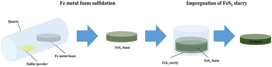
Figure 1. Schematic representation of the synthesis process of the cathode using FeSx foam for thermal batteries.
Experimental
Thermal sulfidation of FeS2 foam was carried out in a sealed quartz tube to prevent oxidation and incorporate the evaporated sulfur. Fe foam (porosity: 95%, pore size: ~450 μm, Alantum Corporation, Seongnam, South Korea) and sulfur powder (purity: 99%, Sigma Aldrich, St. Louis, Missouri, USA) were used as starting materials to fabricate the FeS2 foam. The Fe foam was cut into a circle of diameter 56.2 mm, which was the size of the cathode. The Fe foam and sulfur powder (twice the amount of Fe in terms of molar ratio) were placed in the quartz tube, which was purged with Ar gas and subsequently sealed. The precursors placed in the quartz tube were then sulfidized at 400 and 500°C (HT-400 and HT-500) for 3 h. The heating rate was maintained at 2°C/min. After thermal sulfidation, the quartz tube was slowly cooled to room temperature. All the experiments were performed in a glove box to prevent contact with oxygen and moisture.
FeS2 slurry was impregnated into FeS2 foam to fabricate the thermal battery cathodes. The FeS2 slurry was prepared as follows. FeS2 powder (mean size: 98 μm, purity: 99% LinYi, China) was dispersed in acetone by ball milling using a BYK-111 (Altana) dispersant for 24 h. The initial particle size of the FeS2 powder was about 98 μm; however, the particle size reduced to about 20 μm after ball milling for 24 h. The size reduction of the particles by ball milling has been confirmed in previous studies (Ko et al., 2017). The FeS2 slurry was placed in a glass petri dish along with Fe and FeS2 foam, and the resulting mixtures were left under ambient conditions for several minutes. The mixtures were subsequently dried at 70°C for 24 h to completely remove acetone. A schematic representation of the entire process of cathode fabrication via FeS2 impregnation on Fe foam and the FeS2 foam prepared by thermal sulfidation is shown in Figure 1.
The crystalline phases of FeS2 foams, which were synthesized at different sulfidation temperatures, were analyzed by X-ray diffraction (XRD, PANalytical X'Pert PRO) with Cu Kα radiation. The surface morphological properties and element ratios of the samples were examined using a field-emission scanning electron microscope (Hitachi S-4200) with an energy dispersive X-ray spectrometer (EDX). The resistances of the FeS2 foams were measured at room temperature by electrochemical impedance spectroscopy (EIS, IM6Ex) over a frequency range of 100 mHz−2 MHz with an amplitude voltage of 10 mV.
The cathodes fabricated using the pure Fe and FeS2 foams were used to evaluate the discharge characteristics of thermal battery single cells. Figure 2 shows the general procedure of assembly of the single cell used to confirm the discharge characteristics of the cathode using HT-500 foam.
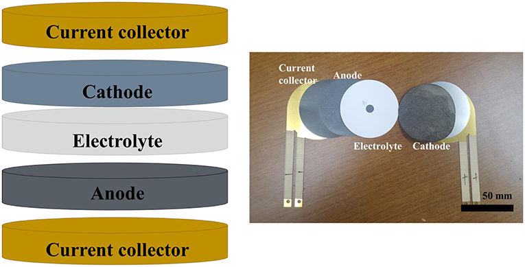
Figure 2. Structure and images of a single cell for a thermal battery.
To verify the characteristics of the cathode, a commercial pellet-type electrode was used as the separator and anode. The discharge test of the single cell was performed under conditions similar to the operating conditions of thermal batteries and by using Daque 9,000 at 500°C with a load of 250 kgf while applying a consecutive pulse current (10 A, 4.5 s → 0 A, 0.5 s). The discharge test was terminated when the voltage dropped below 1.3 V.
Results and Discussion
FeS2 Foam Fabrication According to Sulfidation Temperature
FeS2 foam was fabricated via thermal sulfidation at 400 and 500°C on Fe foams. The surface morphologies of the Fe and FeS2 foams synthesized at different sulfidation temperatures were examined by SEM. Figure 3A shows that the Fe foam had a three-dimensional structure with interconnecting holes (200–450 μm) made up of arch ribs. The arch ribs of the Fe foam had smooth and uniform wrinkles on the highly porous surface. Figures 3B,C shows that HT-400 and HT-500 foams were prepared at different thermal sulfidation temperatures. SEM images of the foams treated by thermal sulfidization revealed that sulfur was deposited entirely on the surface of the arch ribs. Both HT-400 and HT-500 foams had porous structures with no wrinkles on their surfaces (Figures 3B,C) unlike the Fe foam. As the thermal sulfidation temperature increased, the amount of sulfur deposited on the surface of the arch ribs increased along with an increase in the surface grain size. However, the synthesized HT-400 and HT-500 foams increased in terms of grain size with increasing sulfidation temperature but did not exhibit pores and cracks (Figure S1). These results show an improvement in surface conditions over those obtained by Rahman and Wen (2016). In addition, the synthesized HT-400 and HT-500 foams are expected to exhibit stable mechanical strength because they have 3D architectures. Moreover, EDS mapping clearly showed the uniform distribution of S and Fe on the surface of the foams (Figures 3D,E). HT-500 foam consisted of 32.79% of Fe and 67.21% of S with an Fe/S ratio of 2.04, which is very close to the atomic ratio in the formula FeS2 (Table 1). However, HT-400 foam consisted of 38.29% of Fe and 61.17% of S with an Fe/S ratio of 1.60. In other words, the sulfur content of the HT-400 foam was lesser than that of FeS2 (the material of thermal battery cathodes).
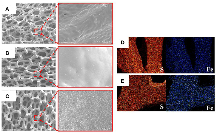
Figure 3. SEM images of (A) Fe, (B) HT-400, and (C) HT-500 foams. EDX images of (D) HT-400 and (E) HT-500 foams.
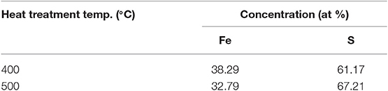
Table 1. Quantification results of EDX at different annealing temperatures.
Figure 4 shows the XRD peaks of HT-400 and HT-500 foams. Both samples showed peaks corresponding to the (111), (200), (210), (211), (220), (311), (222), (023), and (321) planes (JCPDS card no. 42-1340). This exhibits a cubic pyrite (FeS2) structure with the space group of Pa3 (Cabán-Acevedo et al., 2013; Lucas et al., 2013; Miao et al., 2017). However, XRD peaks for FeS of HT-400 foam and the high Fe content by EDS analysis (in Table 1) indicate the coexistence of FeS and FeS2. Pyrrhotite (FeS) causes thermal battery degradation owing to self-discharge by pyrolysis and impurity formation during the operation of thermal batteries (Schoeffert, 2005; Masset and Guidotti, 2008b). In contrast, the HT-500 foam confirmed good crystallinity with high intensity and sharp XRD peaks. To further analyze the crystallinity and phase purity of HT-400 and HT-500 foams, HRTEM and SAED analyses were carried out on them (Figure S2). The HT-400 foam showed lattice spacings of 3.126 and 2.050 Å corresponding to the pyrite (111) and pyrrhotite (208) planes, respectively (Figure S1b). However, the HT-500 foam showed a lattice spacing of 3.126 Å corresponding to the (111) plane (Figure S1c).Thus, the structure of HT-500 foam was similar to that of the cathode material, and HT-500 foam did not contain any FeS; it was expected that there would be no incidental reaction related to FeS during thermal battery discharge.
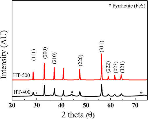
Figure 4. XRD patterns of HT-400 and HT-500 foams.
Figure 5 shows the Nyquist plots of the HT-400 and HT-500 foams obtained from their EIS results (to evaluate their electrochemical properties). From the EIS results, the total ohmic resistance associated with the series resistance of HT-400 and HT-500 foams was determined. The high-frequency intercept at the real axis (Z) corresponds to the total ohmic resistance (Rs) (Cooper and Smith, 2006; Gomez et al., 2011). In addition, a Warburg tail was not observed at low frequencies, indicating that only electrical conduction occurred (without ion conduction) at these frequencies (Sinclair, 1995). The electrical resistances of the HT-400 and HT-500 foams at room temperature were found to be 1.55 × 10⁴ and 9.37 × 10³ Ω, respectively. The diameter of the Nyquist curve semicircle of the HT-400 foam was larger than that of the HT-500 foam, indicating that the electrical resistance of the HT-400 foam was higher than that of the HT-500 foam.
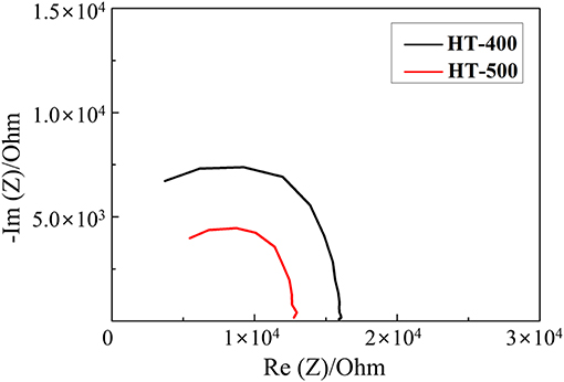
Figure 5. Nyquist plots of HT-400 and HT-500 foams.
These results suggest that the HT-400 foam was synthesized with a mixed phase rather than a single phase, thereby resulting in an increase in the total resistance (Thomas et al., 1998). The structure of HT-500 foam was similar to that of FeS2, and HT-500 foam exhibited more stable electrochemical properties than HT-400 foam. Therefore, HT-400 foam is not discussed in detail in the rest of the study.
Single Cell Assembly Using Synthesized FeS2 Foam
Cathodes for thermal batteries were fabricated using HT-500 and Fe foams to confirm the effect of thermal sulfidation. Both the cells were 16-mm thick and had a diameter of 56.2 mm. Figures 6A,B show images of the Fe foam before and after immersion in FeS2 slurry, respectively. The color of the Fe foam changed after immersion in the FeS2 slurry, indicating that the Fe foam was well-impregnated with the slurry. Figures 6C,D show images of the HT-500 foam before and after FeS2 slurry impregnation, respectively. The color of the FeS2 slurry impregnated HT-500 foam was similar to that of the FeS2 slurry impregnated Fe foam. Figures 6E,F show cross-sectional SEM images of the HT-500 foam before and after FeS2 slurry impregnation, respectively. The figures show that before impregnation, the HT-500 foam comprised void spaces. Such a frame structure can prevent separation of the cathode powder at the operating temperature of thermal batteries and can contain a large amount of active material. After impregnation, a large amount of fine FeS2 particles filled the voids and increased the density of the HT-500 foam.
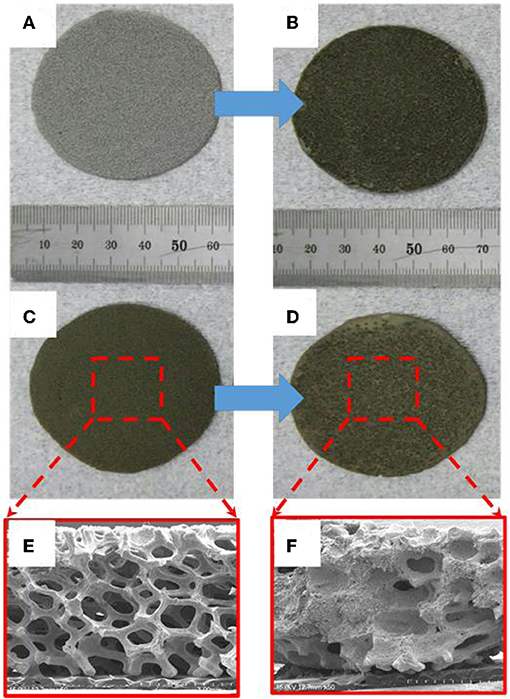
Figure 6. Image of pure Fe foam (A) before and (B) after impregnation with FeS2 slurry. HT-500 foam (C) before and (D) after impregnation with FeS2 slurry. Cross-section of the SEM image of HT-500 (E) before and (F) after impregnation with FeS2 slurry.
Evaluation of Discharge Characteristics of the Assembled Single Cells
Figure 7 shows the discharge performance of the HT-500 and Fe foam cathodes and the assembled cells. The fabricated cells were discharged into the pulse mode at the thermal battery operating temperature. The inversion voltage plateaus of the thermal battery using FeS2 had three parts: the Z-phase reacts with FeS2 and Li to form Li2Fe2S4, the J-phase generates Li3Fe2S4, and the X-phase was the final reaction step to produce elemental lithium sulfur and iron (Choi et al., 2014). The X-phase occurs at 1.3 V (Ulissi et al., 2018).
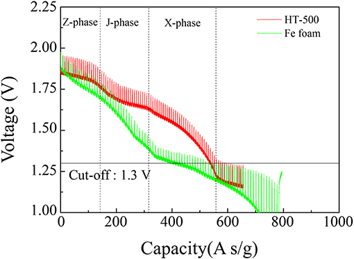
Figure 7. Discharge graphs of cathodes using Fe and HT-500 foams.
In this study, we confirmed the capacity of the single thermal cell by setting the cut-off value to 1.3 V, which is the voltage at which the main reaction of the thermal battery cathode is completed, to confirm the final reaction of FeS2. Table 2 lists the thicknesses, foam weights, total electrode weights, and discharge capacities of the cathode using Fe and HT-500 foams. To determine the effect of Fe and HT-500 foams, the thermal battery capacity was calculated by considering the total cathode weight. The discharge capacity of the Fe foam cathode at the cut-off value of 1.3 V was found to be 404.04 A s/g. In contrast, the cell using the HT-500 foam cathode showed a discharge capacity of 538.38 A s/g. The reason for the higher discharge capacity of the HT-500 foam was the chemical reaction that occurs during discharging.
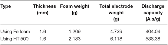
Table 2. Discharge performances of cathodes using Fe foam and HT-500.
Based on the discharge evaluation shown in Figure 8, the total polarization of the single battery with a cathode frame was calculated using the formula reported by Fujiwara et al. (2011). The total polarization was calculated using the following equation:
where Rt: total polarization, Ω; Voc: open circuit voltage, V; Vcc: close circuit voltage, V; and I: discharge current, A.
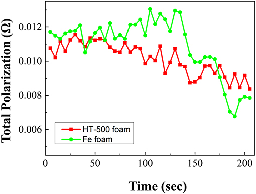
Figure 8. Total polarization graphs of cathodes using Fe and HT-500 foams.
During discharge, the total polarization of the Fe foam cell is higher than that of the HT-500 cell. Furthermore, a strong internal resistance was observed during the reaction between 100 and 150 s. These results are consistent with the results in Figure 7 which shows a region where the performance of the Fe foam cell rapidly decreased. These results indicate that the internal resistance increases as an intermediate product (in the X-phase and J-phase) during the thermal battery discharge is rapidly generated because of the reaction between the Fe foam and the melted electrolyte (Kam and Johnson, 1980). In addition, the total polarization appears to be lower after 150 s, which is due to the electrons generated upon the reaction of Fe and LiS2, a byproduct of the thermal battery reaction (Peled and Lavi, 1998; Strauss and Peled, 2000; Masset and Guidotti, 2008a). Because this occurs when the thermal battery reaction is completed, the discharge capacity is less affected (Figure S3). These results have an impact on the discharge characteristics of the battery, causing a reduction in its capacity when compared with batteries using the HT-500 foam. Table 3 shows a comparison of the discharge characteristics of the sample fabricated in this study to those fabricated through other methods. The thermal battery discharge profile depends on the pulse current. Generally, as the discharge current increases, the operation time and capacity of the battery reduce (Wesolowski and Papenguth, 2010; Ceriotti et al., 2011). These cells can be fabricated with diameters larger than those fabricated by other methods.
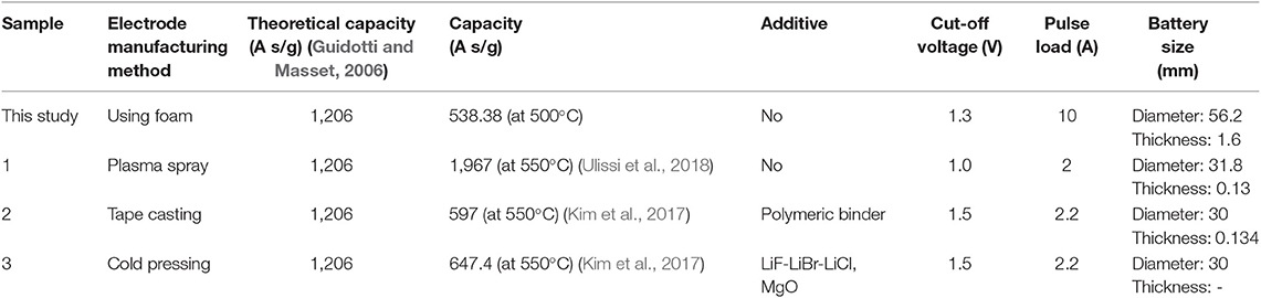
Table 3. Characteristics of the cathodes based on production method.
Furthermore, we compared the discharge performances of the cold-press electrode and the electrode using HT-500 (Figure S4). Typically, the thickness of the cathode electrode manufactured by the cold-press method is 0.5 mm, and that of the HT-500 cathode was also 0.5 mm. The former showed a capacity of 996.0 A s/g and the latter showed a capacity of 1251.2 A s/g. The capacity of the cathode using HT-500 foam was 1.2 times that of the cold-press electrode. The discharge characteristics of the single cell using the HT-500 foam show that the cell can be utilized to manufacture a thermal battery electrode.
Conclusions
HT-500 foam was synthesized through a sulfidation process for use as a thermal cathode frame. The HT-500 foam reduced the contact resistance between the active material and the Fe foam because of the formation of FeS2 crystals, which was dependent on the thermal sulfidation temperature. The foam was used as a frame for thermal battery cathodes, and the discharge capacity of the cathode was measured. The discharge characteristics of the HT-500 and Fe foam cathodes were compared. The discharge capacity of a single cell with the HT-500 foam was 538.38 A s/g, which is 1.3 times higher than that of the single cell using the Fe foam. These results indicate that the discharge characteristics and mechanical strength of thermal battery cathodes can be improved by decreasing their interfacial resistance by coating active materials on their surfaces. Thus, HT-500 foam is a promising cathode frame for high-performance thermal batteries.
Data Availability Statement
All datasets generated for this study are included in the article/Supplementary Material.
Author Contributions
The concept for this study was designed by YY, H-WC, and J-HL. IK designed the experiment. IK and SW performed experiments on material selection and sulfidation temperature conditions. JK performed discharge evaluation. YY and J-HL performed raw material selection and helped in morphology analysis. H-WC and S-HK coordinates the interpretation of the electrochemical assessment. All authors helped write the manuscript.
Funding
This work was supported by Defense Acquisition Program Administration and Agency for Defense Development under the contract (UD190006GD). This work was also supported by the Gachon University research fund of 2019 (GCU-2019-0297).
Conflict of Interest
The authors declare that the research was conducted in the absence of any commercial or financial relationships that could be construed as a potential conflict of interest.
Supplementary Material
The Supplementary Material for this article can be found online at: https://www.frontiersin.org/articles/10.3389/fchem.2019.00904/full#supplementary-material
Abbreviations
SEM, scanning electron microscopy; EDX, energy dispersive X-ray spectroscopy; XRD, X-ray diffraction.
References
Au, M. (2003). Nanostructured thermal batteries with high power density. J. Power Sources 115, 360–366. doi: 10.1016/S0378-7753(02)00627-4
Cabán-Acevedo, M., Liang, D., Chew, K. S., DeGrave, J. P., Kaiser, N. S., and Jin, S. (2013). Synthesis, characterization, and variable range hopping transport of pyrite (FeS2) nanorods, nanobelts, and nanoplates. ACS Nano 7, 1731–1739. doi: 10.1021/nn305833u
Ceriotti, M., Corrà, M., Orazio, L. D., Doriguzzi, R., Facchin, D., Gună, S. T., et al. (2011). “Is there light at the ends of the tunnel? Wireless sensor networks for adaptive lighting in road tunnels,” in Proceedings of the 10th ACM/IEEE International Conference on Information Processing in Sensor Networks (Chicago, IL), 12–14.
Cha, Y. L., Park, I. H., Moon, K. H., Kim, D. H., Jung, S. I., and Yoon, Y. S. (2018). Simultaneous control of phase transformation and crystal of amorphous TiO2 coating on MWCNT surface. J. Korean Ceram. Soc. 55, 618–624. doi: 10.4191/kcers.2018.55.6.09
Choi, Y., Cho, S., and Lee, Y. S. (2014). Effect of the addition of carbon black and carbon nanotube to FeS2 cathode on the electrochemical performance of thermal battery. J. Ind. Eng. Chem. 20, 3584–3589. doi: 10.1016/j.jiec.2013.12.052
Cooper, K. R., and Smith, M. (2006). Electrical test methods for on-line fuel cell ohmic resistance measurement. J. Power Sources 160, 1088–1095. doi: 10.1016/j.jpowsour.2006.02.086
Ferrer, I. J., and Sánchez, C. (1991). Characterization of FeS2 thin films prepared by thermal sulfidation of flash evaporated iron. J. Appl. Phys. 70, 2641–2647. doi: 10.1063/1.349377
Fujiwara, S., Inaba, M., and Tasaka, A. (2011). New molten salt systems for high temperature molten salt batteries: ternary and quaternary molten salt systems based on LiF–LiCl, LiF–LiBr, and LiCl–LiBr. J. Power Sources 196, 4012–4018. doi: 10.1016/j.jpowsour.2010.12.009
Giagloglou, K., Payne, J. L., Crouch, C., Gover, R. K. B., Connor, P. A., and Irvine, J. T. S. (2016). Zirconium trisulfide as a promising cathode material for Li primary thermal batteries. J. Electrochem. Soc. 163, A3126–A3130. doi: 10.1149/2.1351614jes
Gomez, J., Nelson, R., Kalu, E. E., Weatherspoon, M. H., and Zheng, J. P. (2011). Equivalent circuit model parameters of a high-power Li-ion battery: thermal and state of charge effects. J. Power Sources 196, 4826–4831. doi: 10.1016/j.jpowsour.2010.12.107
Guidotti, R., and Preston, S. (2007). “Electrode fabrication processes for thermal batteries,” in 5th International Energy Conversion Engineering Conference and Exhibit (St. Louis, MO), 25–27.
Guidotti, R. A., and Masset, P. (2006). Thermally activated (“thermal”) battery technology Part I: an overview. J. Power Sources 161, 1443–1449. doi: 10.1016/j.jpowsour.2006.06.013
Guidotti, R. A., and Masset, P. J. (2008). Thermally activated (“thermal”) battery technology Part IV: anode materials. J. Power Sources 183, 388–398. doi: 10.1016/j.jpowsour.2008.04.090
Guidotti, R. A., Reinhardt, F. W., Dai, J., Roth, J., and Reisner, D. E. (2002). Characterization of plasma-sprayed pyrite/electrolyte composite cathodes for thermal batteries. J. New Mat. Electrochem. Syst. 5, 273–279. Available online at: https://www.researchgate.net/profile/Ronald_Guidotti/publication/267725303_Characterization_of_Plasma-Sprayed_PyriteElectrolyte_Composite_Cathodes_for_Thermal_Batteries/links/547784960cf2a961e483ac59.pdf
Guidotti, R. A., Reinhardt, F. W., Jinxiang, D., Xiao, T. D., and Reisner, D. (2000). “Thermal-sprayed, thin-film pyrite cathodes for thermal batteries-discharge-rate and temperature studies in single cells,” in 35th Intersociety Energy Conversion Engineering Conference and Exhibit (Las Vegas, NV), 24–28.
Ji, H., Zhang, L., Pettes, M. T., Li, H., Chen, S., Shi, L., et al. (2012). Ultrathin graphite foam: a three-dimensional conductive network for battery electrodes. Nano. Lett. 12, 2446–2451. doi: 10.1021/nl300528p
Jin, C., Fu, L., Zhu, J., Yang, W., Li, D., and Zhou, L. (2018). A hierarchical carbon modified nano-NiS2 cathode with high thermal stability for a high energy thermal battery. J. Mater. Chem. A. 6, 7123–7132. doi: 10.1039/C8TA00346G
Jin, C., Zhou, L., Fu, L., Zhu, J., Li, D., and Yang, W. (2017). The acceleration intermediate phase (NiS and Ni3S2) evolution by nanocrystallization in Li/NiS2 thermal batteries with high specific capacity. J. Power Sources 352, 83–89. doi: 10.1016/j.jpowsour.2017.03.119
Kam, K. W., and Johnson, K. E. (1980). Cycle voltammetry of Li2S, FeS and FeS2 in LiC1-KCl eutectic melt. J. Electroanal. Chem. 115, 53–64. doi: 10.1016/S0022-0728(80)80495-5
Kang, S. H., Lee, J. U., Hur, T., Cheong, H. W., and Yi, J. (2016). Heat treatment effect on microstrain and electrochemical performance of nano-sized FeS2 cathode for thermal batteries. Int. J. Electrochem. Sci. 6, 4371–4379. doi: 10.20964/2016.06.41
Kim, I. Y., Shin, S. Y., Ko, J. H., Lee, K. S., Woo, S. P., Kim, D. K., et al. (2017). Functional Li-M (Ti, Al, Co, Ni, Mn, Fe)-O energy materials. J. Korean Ceram. Soc. 54, 9–22. doi: 10.4191/kcers.2017.54.1.11
Ko, J., Kim, I. Y., Jung, H. M., Cheong, H., and Yoon, Y. S. (2017). Thin cathode for thermal batteries using a tape-casting process. Ceram. Int. 43, 5789–5793. doi: 10.1016/j.ceramint.2017.01.126
Leviatan, T. (2011). “Development of thin layer electrochemical components for advanced thermal batteries,” in 9th Annual International Energy Conversion Engineering Conference (IECEC) (San Diego, CA).
Liu, X., Ho, J. Y. L., Wong, M., Kwok, H. S., and Liu, Z. (2016). Synthesis, characterization and fabrication of ultrathin iron pyrite (FeS2) thin films and field-effect transistors. RSC Adv. 6, 8290–8296. doi: 10.1039/C5RA23344E
Lucas, J. M., Tuan, C.-C., Lounis, S. D., Britt, D. K., Qiao, R., Yang, W., et al. (2013). Ligand-controlled colloidal synthesis and electronic structure characterization of cubic iron pyrite (FeS2) nanocrystals. Chem. Mat. 25, 1615–1620. doi: 10.1021/cm304152b
Masset, P., and Guidotti, R. A. (2007). Thermal activated (thermal) battery technology Part II. molten salt electrolytes. J. Power Sources 164, 397–414. doi: 10.1016/j.jpowsour.2006.10.080
Masset, P., Schoeffert, S., Poinso, J.-Y., and Poignet, J.-C. (2005). LiF-LiCl-LiI vs. LiF-LiBr-KBr as molten salt electrolyte in thermal batteries. J. Electrochem. Soc. 152, A405–A410. doi: 10.1149/1.1850861
Masset, P. J., and Guidotti, R. A. (2008a). Thermal activated (“thermal”) battery technology Part IIIa: FeS2 cathode material. J. Power Sources 177, 595–609. doi: 10.1016/j.jpowsour.2007.11.017
Masset, P. J., and Guidotti, R. A. (2008b). Thermal activated (“thermal”) battery technology Part IIIb: sulfur and oxide based cathode materials. J. Power Sources 178, 456–466. doi: 10.1016/j.jpowsour.2007.11.073
Miao, R., Dutta, B., Sahoo, S., He, J., Zhong, W., Cetegen, S. A., et al. (2017). Mesoporous iron sulfide for highly efficient electrocatalytic hydrogen evolution. J. Am. Chem. Soc. 139, 13604–13607. doi: 10.1021/jacs.7b07044
Peled, E., and Lavi, Y. (1998). Li/CPE/FeS2 rechargeable battery. Electrochim. Acta 43, 1593–1599 doi: 10.1016/S0013-4686(97)10059-7
Preto, S. K., Tomczuk, Z., von Winbush, S., and Roche, M. F. (1983). Reactions of FeS2, CoS2, and NiS2 electrodes in molten LiCI-KCI electrolytes. Electrochem. Soc. 130, 264–273. doi: 10.1149/1.2119692
Rahman, M. A., and Wen, C. (2016). A study of the capacity fade of porous NiO/Ni foam as negative electrode for lithium-ion batteries. Ionics 22, 173–184. doi: 10.1007/s11581-015-1542-8
Schoeffert, S. (2005). Thermal batteries modeling, self-discharge and self-heating. J. Power Sources 142, 361–369. doi: 10.1016/j.jpowsour.2004.09.038
Sinclair, D. C. (1995). Characterization of electro-materials using ac impedance spectroscopy. Cerámicay Vidrio 32, 55–65.
Singh, P., Guidotti, R. A., and Reisner, D. (2004). AC impedance measurements of molten salt thermal batteries. J. Power Sources 138:323–326. doi: 10.1016/j.jpowsour.2004.06.038
Strauss, E., and Peled, E. (2000). Study of phase changes during 500 full cycles of Li/composite polymer electrolyte/FeS2 battery. Electrochim. Acta 45, 1519–1525 doi: 10.1016/S0013-4686(99)00368-0
Sun, C., Li, Y., Jin, J., Yang, J., and Wen, Z. (2019). ZnO nanoarray-modified nickel foam as a lithiophilic skeleton to regulate lithium deposition for lithium-metal batteries. J. Mater. Chem. A 7, 7752–7759. doi: 10.1039/C9TA00862D
Thomas, B., Cibik, T., Höpfner, C., Diesner, K., Ehlers, G., Fiechter, S., et al. (1998). Formation of secondary iron-sulphur phases during the growth of polycrystalline iron pyrite (FeS2) thin films by MOCVD. J. Mater. Sci. Mater. Electron. 9, 61–64. doi: 10.1023/A:1008888801424
Ulissi, U., Ito, S., Hosseini, S. M., Varzi, A., Aihara, Y., and Passerini, S. (2018). High capacity all-solid-state lithium batteries enabled by pyrite-sulfur composites. Adv. Energy Mater. 8:1801462. doi: 10.1002/aenm.201801462
Wesolowski, D. E., and Papenguth, H. W. (2010). “Study of cell performance in long-life thermal battery design space,” in 44th Power Sources Conference (Las Vegas, NV), 14–17.
Wu, Z., Sun, L., and Wang, J. (2018). Progresses on the optimal processing and properties of highly porous rare earth silicate thermal insulators. J. Korean Ceram. Soc. 55, 527–555. doi: 10.4191/kcers.2018.55.6.12
Keywords: thermal battery, FeS2 foam, metal foam, thermal sulfidation, cathode frame
Citation: Kim IY, Woo SP, Ko J, Kang S-H, Yoon YS, Cheong H-W and Lim J-H (2020) Binder-Free Cathode for Thermal Batteries Fabricated Using FeS2 Treated Metal Foam. Front. Chem. 7:904. doi: 10.3389/fchem.2019.00904
Received: 03 September 2019; Accepted: 13 December 2019;
Published: 10 January 2020.
Edited by:
Nosang Vincent Myung, University of California, Riverside, United StatesReviewed by:
Pankaj Madhukar Koinkar, Tokushima University, JapanXianhong Rui, Guangdong University of Technology, China
Copyright © 2020 Kim, Woo, Ko, Kang, Yoon, Cheong and Lim. This is an open-access article distributed under the terms of the Creative Commons Attribution License (CC BY). The use, distribution or reproduction in other forums is permitted, provided the original author(s) and the copyright owner(s) are credited and that the original publication in this journal is cited, in accordance with accepted academic practice. No use, distribution or reproduction is permitted which does not comply with these terms.
*Correspondence: Hae-Won Cheong, hwcheong@add.re.kr; Jae-Hong Lim, limjh@gachon.ac.kr