 Chen-Hao Chang
 Jonathan Casas
 Amit K. Sanyal
 Victor H. Duenas
- Department of Mechanical and Aerospace Engineering, Syracuse University, Syracuse, NY, United States
Functional electrical stimulation (FES)-induced cycling is a rehabilitation strategy that activates lower-limb muscles to achieve coordinated pedaling in individuals with movement disorders. An electric motor is included in-the-loop assisting the rider as needed to prolong exercise duration and mitigate muscle fatigue. Power tracking objectives have been prescribed for motorized FES-cycling, where muscles and the electric motor are assigned to track desired cadence (speed) and torque trajectories. However, predetermined desired trajectories can yield poor cycling performance since the functional capacity of each individual is unknown. In particular, when muscles are tasked to track a desired torque, a dynamic approach is well-motivated to adjust the torque demand for the rider in real-time (e.g., a constant torque demand may be unfeasible throughout a cycling session since muscles fatigue). In this paper, input-output data is exploited using a finite-time algorithm to estimate the target desired torque leveraging an estimate of the active torque produced by muscles via FES. The convergence rate of the finite-time algorithm can be adjusted by tuning selectable parameters. The cycle-rider system is modeled as a nonlinear, time-varying, state-dependent switched system to activate lower-limb muscles and an electric motor. To achieve cadence and torque tracking, nonlinear robust tracking controllers are designed for muscles and motor. A robust sliding mode controller is designed for the electric motor to track a desired constant cadence trajectory. Moreover, an integral torque feedback controller is designed to activate quadriceps, hamstrings, and gluteus muscle groups to track the desired torque trajectory computed by the finite-time algorithm. A Lyapunov-based stability analysis is developed to ensure exponential tracking of the closed-loop cadence error system and global uniformly ultimate bounded (GUUB) torque tracking. A discrete-time Lyapunov-based stability analysis leveraging a recent tool for finite-time systems is developed to ensure convergence and guarantee that the finite-time algorithm is Hölder continuous. The developed tracking controllers for the muscles and electric motor and finite-time algorithm to compute the desired torque are implemented in real-time during cycling experiments in seven able-bodied individuals. Multiple cycling trials are implemented with different gain parameters of the finite-time torque algorithm to compare tracking performance for all participants.
1 Introduction
There are approximately 17,730 new spinal cord injury (SCI) cases each year that affect individuals by limiting their mobility and independence, and diminishing their quality of life Kirshblum and Lin (2018); Hornby et al. (2020). Rehabilitation technologies have been developed in the past decades to restore mobility and improve the quality of life of individuals with paralysis. Powered rehabilitation machines, such as exoskeletons and motorized exercise machines, are designed to assist individuals to improve their gait kinematics, metabolic and cardiorespiratory responses, balance, and mobility Hornby et al. (2020); Field-Fote and Roach (2011); Hong et al. (2020); Kressler et al. (2018); Kressler and Domingo (2019); Sale et al. (2018). Further, functional electrical stimulation (FES) is a therapeutic approach that evokes artificial muscle contractions by applying electrical stimuli across skeletal muscles, which can provide improvements in muscle strength, blood flow, bone mineral density, and range of motion Doucet et al. (2012); Reed (1997); Peckham and Knutson (2005). FES has been combined with electrical motors to develop hybrid rehabilitation machines that can mitigate muscle fatigue and prolong the benefits of muscle stimulation by exploiting the electric motor’s torque reliability for locomotion Ho et al. (2014); Chang et al. (2017); Nataraj et al. (2017); Alibeji et al. (2017); Chang et al. (2022), upper-limb rehabilitation McCabe et al. (2015); Rouse et al. (2018), and FES-cycling Bellman et al. (2017); Duenas et al. (2019); Ghanbari et al. (2019); Chang and Duenas (2019); Chang et al. (2020). Motorized FES-cycling has been recommended for lower-limb rehabilitation in individuals with limited function who otherwise would not be able to engage in physical activity, since stationary cycling reduces the risks of falling (e.g., compared to assisted walking). However, the highly nonlinear, uncertain muscle dynamics pose technical challenges for designing closed-loop FES feedback controllers Lynch and Popovic (2008). Moreover, FES accelerates the onset of muscle fatigue Winter (2009); Downey et al. (2017). Therefore, innovative control designs are needed to improve the performance of hybrid machines for cycling.
Cadence and power tracking are two main control objectives for FES-cycling, which have motivated the design and evaluation of controllers leveraging different techniques. Robust controllers have been designed and implemented to track desired cadence trajectories with and without motorized assistance Bellman et al. (2017); Bellman et al. (2016); Kawai et al. (2019); Farhoud and Erfanian (2014). Adaptive-based control methods involving switched dynamics have been recently introduced to compensate for model uncertainties and improve tracking performance using iterative learning Ghanbari et al. (2019), repetitive learning Duenas et al. (2019), and concurrent learning Casas et al. (2020) approaches. Power tracking controllers were designed to track predetermined desired torque trajectories using impedance and admittance techniques Chang et al. (2022); Cousin et al. (2019), Cousin et al. (2020) and a model-based feedback approach Hunt et al. (2004). However, existing power tracking controllers usually implement predetermined desired torque trajectories and thus are prone to experience degraded performance due to the time-varying muscle dynamics and fatigue. Limited torque tracking performance may require manual adjustments of the desired torque demand, which is not practical in clinical settings. Thus, technical challenges remain to develop control methods that can adjust the desired torque trajectory in real-time to improve power tracking, while capturing the muscle force-producing ability and guaranteeing stability.
A potential strategy to improve power tracking in FES-cycling is to adjust the desired torque target based on collected input-output data. For example, powermeters are usually integrated in lower-limb cycles to measure the applied torque about the crank. However, the torque measurements provided by powermeters include the collection of passive and active torque contributions by the rider. Therefore, recent studies on FES-cycling have calculated estimates of the active torque generated by muscles to segregate their torque contributions about the crank Cousin et al. (2020). Another potential strategy to quantify active torque produced by muscles in real-time is using an ultrasound imaging sensor approach Sheng et al. (2020). This approach enables the estimation of the muscle dynamics and can provide surrogate signals to explicitly quantify muscle fatigue, which could be exploited as a feedforward control term or to modify the electric motor assistance for cycling. However, validation of the approach in Sheng et al. (2020) for cycling is still needed to ensure robust measurements. Impedance and admittance controllers for FES-cycling have implemented an indirect torque approach in which changes in the rider’s torque influence the cadence trajectory or vice versa (i.e., changes in cadence impact the torque trajectory) Chang et al. (2022); Cousin et al. (2019); Cousin et al. (2020). However, it remains unclear how to exploit estimates of the active muscle torque to adjust the desired torque trajectory in real-time independently and without affecting the cycle’s cadence. In addition, the approach to adjust the torque demand needs to guarantee stability of the closed-loop torque error system and have fast convergence (e.g., finite-time convergence) to capture the rider’s time-varying ability to generate active torque (e.g., due to muscle fatigue).
Finite-time control techniques are well-studied in control systems to guarantee convergence to an equilibrium in finite time and provide robustness with respect to disturbances. Thus, control performance can be improved by leveraging finite-time stability tools to obtain a faster rate of convergence compared to traditional asymptotic results. Stability results for continuous autonomous systems, non-autonomous (i.e., time-varying systems), switched, and hybrid systems have been reported in Bhat and Bernstein (2000); Romero and Benosman (2021); Haddad et al. (2008); Garg and Panagou (2019). Finite-time stability results have been extended for adaptive parameter estimation Garg et al. (2018), discontinuous (using Filippov solutions) and impulsive systems Hui et al. (2009); Nersesov and Haddad (2008). A finite-time method has been integrated with extremum seeking to maximize or minimize a cost function and achieve real-time optimization with a fast convergence rate Poveda and Krstic (2020); Guay and Benosman (2021). Recently, a discrete finite-time framework has leveraged input-output data to learn uncertain dynamics and guarantee robustness and nonlinear stability Sanyal (2021). However, it is an open problem to explore the feasibility of finite-time control tools to improve torque tracking performance and ensure fast convergence (i.e., provide performance guarantees) in the nonlinear, uncertain FES-cycling system with additive disturbances and input switching across lower-limb muscles.
In this paper, cadence and torque controllers are designed for power tracking using a motorized FES-cycling system. The contribution in this paper is the design, analysis and experimental implementation of closed-loop controllers to dynamically adjust the desired active torque produced by the rider’s muscles and to track cadence and torque objectives tasked to the electric motor and muscles, respectively. The motivation is to update the desired active torque per crank cycle leveraging a finite-time control technique as a tool to customizing the torque trajectories for each participant while guaranteeing stability of the FES-cycling system. The cycle-rider system is modeled as a nonlinear, time-varying, state-dependent switched dynamical system. To capture the time-varying muscle capacity to evoke active torque, a finite-time torque control algorithm is developed to adjust the desired torque in real-time by leveraging estimates of the active torque produced by muscles. The finite-time torque controller leverages input-output data and is designed in discrete-time to adjust the peak torque demand per crank cycle, and thus converge in finite-time. This torque strategy departs from existing cycling studies that implement predetermined desired torque trajectories that may require manual tuning as the rider fatigues. A robust sliding-mode controller using an integral torque signal is designed to apply FES to the hamstrings, quadriceps, and gluteus muscle groups to track the desired torque trajectory. Similarly, a robust sliding-mode controller is designed for the electric motor to achieve the desired cadence tracking objective. A Lyapunov-based stability analysis is developed to ensure exponential cadence tracking and a GUUB result for torque tracking. A discrete-time Lyapunov-based analysis is used to ensure the finite-time torque controller that generates the desired trajectory is Hölder continuous. Experimental results in seven able-bodied individuals are presented to examine the feasibility of the developed methods. Cycling trials are implemented with different control gains in the finite-time torque controller to illustrate the FES-cycling performance. A discussion on the obtained experimental results and the future work are described subsequently.
2 Cycle-rider dynamic model with input switching
A single degree-of-freedom stationary cycle and rider can be modeled as Bellman et al. (2017).
where
respectively, where the FES control input each muscle is denoted by
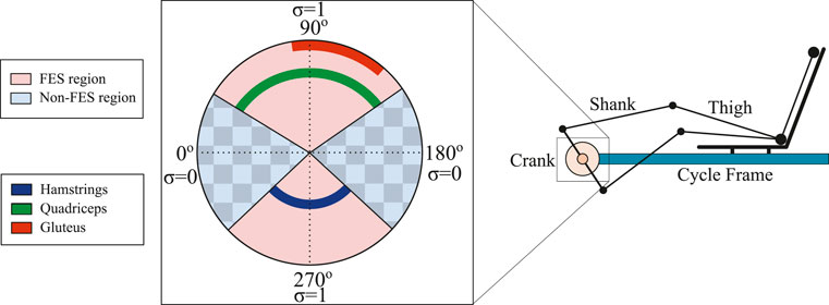
FIGURE 1. Schematic of the muscle stimulation patterns based on the crank angle to yield forward pedaling. The custom stimulation regions for each muscle group are calculated based on the effectiveness to transfer torque about the crank as in Bellman et al. (2017). The crank cycle is segregated into FES and non-FES regions. Within the FES regions, muscles are stimulated to achieve the desired torque tracking objective. Within the non-FES regions, FES is not applied due to the low effectiveness to produce active torque. The electric motor is activated during the entire crank cycle to achieve the cadence tracking objective.
Cycles are outfitted with powermeters that measure the net torque contributions about the crank. Hence, direct measurements of the active torque contributions by muscles are not readily available. Thus, an estimate of the active torque produced by muscles is obtained similarly to Cousin et al. (2020) for the subsequent control design. The measurable torque
where
where
The torque applied by the electric motor about the crank is defined as
where
The derivation of the kinematics and dynamics of the switched FES-cycling system in (Eq. 1) have been introduced in Bellman et al. (2017); Bellman (2015). The following properties and assumption of the switched system introduce lower and upper bounds for each term in (Eq. 1), which will be exploited in the subsequent control design and stability analysis.
Property 1. The positive inertia M(q) satisfies the inequalities cm ≤ M(q) ≤ cM, where cm and cM are known positive constants Lewis et al. (2004).
Property 2.
Property 3. |G(q)| ≤ cg, where cg is a known positive constant Lewis et al. (2004).
Property 4.
Property 5.
Property 6. The lumped muscle switching control effectiveness is bounded as
Property 7. The control effectiveness of motor is bounded as
Assumption 1. |d(t)| ≤ cd, where cd is a known positive constant.
3 Control development
The control design is segregated into cadence tracking control objective, finite-time control algorithm to generate the desired torque trajectory, and torque tracking control objective. The first objective is to design a cadence controller for the electric motor to track a desired constant cadence trajectory. The second objective is to design a discrete-time finite-time controller that generates the target amplitude for the desired torque trajectory. The last objective is to design a torque controller for the muscles via FES to track the desired torque trajectory.
3.1 Cadence tracking control
The measurable angular position tracking error
where
where the auxiliary signal
The upper bound for the auxiliary signal in (Eq. 10) can be obtained by using Properties one to four, Assumption 1 as
where
Given the open-loop error system in (Eq. 9), the cadence control input for the electric motor ue can be designed as
where
3.2 Finite-time control
The purpose of the finite-time controller is to compute the target amplitude of the desired torque trajectory. The implementation of arbitrary or predetermined torque trajectories is susceptible to yield suboptimal cycling performance since the rider’s capacity is uncertain and time-varying (e.g., after a neurological disorder, people retain different levels of residual function). In addition due to the FES-induced muscle fatigue, motivation exists to update the desired torque amplitude each cycle and eliminate the need to perform manual adjustments. The discrete finite-time controller is designed as follows.
The desired torque trajectory
where
where τpeak is the measurable peak active torque generated by muscles during the last crank cycle and defined as
where the estimate of the active torque
Taking the forward difference of (Eq. 16) (i.e., ΔΩ(ti) ≜Ω(ti+1) − Ω(ti)) yields
The update law to generate the torque amplitude is designed as
where
β ∈ (0, 1), and
3.3 Torque control tracking
The purpose of the torque controller is to track the desired torque trajectory in the FES-regions as depicted in Figure 1. To quantify the torque control objective, an integral-like error signal
where τd is the desired torque trajectory defined in (Eq. 15). Taking the time derivative of (Eq. 22), setting the initial conditions to zero, and substituting for (Eqs 2, 5) yields
The muscle control input can be designed as
where
4 Stability analysis
The stability of cadence and torque tracking controllers that activate the electric motor and apply FES to muscles, respectively, can be examined independently. Theorem 1 shows that given the closed-loop cadence error system in (Eq. 14), the cadence controller in (Eq. 13) achieves exponential tracking. Theorem 2 shows that the closed-loop error system in (Eq. 21) using the discrete finite-time controller in (Eq. 19) is stable and Hölder continuous in discrete time. Theorem 3 shows that given the closed-loop torque error system in (Eq. 25), the torque controller in (Eq. 24) achieves GUUB tracking.
4.1 Cadence tracking
Theorem 1. Given the closed-loop error system in (Eq. 14), the controller in (Eq. 13) ensures exponential tracking in the sense that
provided the following sufficient gain conditions are satisfied
Proof. Let
which satisfies the following inequalities
where
The generalized time derivative of (Eq. 28) can be upper bounded by substituting (Eqs 2, 11), and using Properties 6–7 as
Provided the gain conditions in (Eq. 27) are satisfied, the inequality in (Eq. 31) can be further upper bounded as
The upper bound in (Eq. 29) can be substituted into (Eq. 32) to yield
where
4.2 Finite-time control
Theorem 2. Given the closed-loop error system in (21), the update law in (19) ensures (21) is Hölder continuous in discrete time with exponent
where
and
Proof.Let
Taking the first order forward difference (i.e.,
After substituting the closed-loop error system in (Eq. 21) into (Eq. 37), the following expression is obtained
which can be further expressed as
where δ ≜ 1 − β and
Leveraging the result in Sanyal (2021) and the fact that Vf(ti+1) ≤ Vf(ti) from (Eq. 39), the following inequality can be obtained to provide an upper bound for all cycles.
Re-arranging the previous inequality yields
Since
4.3 Torque tracking
Theorem 3. Given the closed-loop error system in (Eq. 25), the controller in (Eq. 24) ensures GUUB tracking in the sense that
provided the following sufficient gain condition is satisfied
Proof. Let
Let eτ(t) be a Filippov solution to the differential inclusion
An upper bound for the previous expression can be obtained by using Property 6 and substituting the upper bound of τd to yield
Provided the gain condition in (Eq. 47) is satisfied, the inequality in (Eq. 50) can be further upper bounded as
where
5 Experimental results
Experiments are provided to demonstrate the performance of the designed controllers developed in (Eqs 13, 19, 24). The control inputs are commanded as stimulation intensities (i.e., pulse width control) to activate the quadriceps, gluteus, and hamstrings muscle groups and as currents to the electric motor. Seven able-bodied individuals (six males aged 19–29 years and one female aged 19 years) participated in the FES-cycling protocol at Syracuse University. Written informed consent was obtained from each participant, as approved by the Institutional Review Board (IRB) at Syracuse University. The participants were instructed and reminded through the cycling protocol to avoid voluntarily contributing to the pedaling task. Individuals were not informed of the desired cadence or torque trajectories.
5.1 Experimental setup
Testing was performed using a recumbent cycle (Sun Seeker ECO-TAD SX) mounted on an indoor trainer and adapted with orthotic boots as shown in Figure 2. A brushed 24 VDC electric motor was mounted to drive the chain. An optical encoder (H1, US Digital) was mounted at the crank to measure the crank position and a SRM Science Road Wireless Power Meter with a custom Torque Analysis Box measured and broadcasted the torque data. An arduino Mega is used to convert the torque measurements sent by the Torque Analysis Box to a digital signal that can be used as feedback for the torque controller. The controllers were implemented on a desktop computer (Windows 10 OS) running a real-time target (QUARC 2.6, Quanser) via MATLAB/Simulink 2018a (MathWorks Inc.) with a sample rate of 1 kHz. The Quanser QPIDe DAQ board was used to read the encoder signal and the digital torque signal from the Arduino, and to control the motor driver (Advanced Motion Controls)1 operating in current-controlled mode. A current-controlled stimulator (RehaStim, Hasomed GmbH) delivered biphasic, symmetric, rectangular pulses to the participant’s quadriceps, gluteus, and hamstrings muscle groups. Self-adhesive PALS® electrodes (3 by 5 inches)2 were placed on each muscle group in both legs. The stimulation current amplitude and stimulation frequency were fixed at 80 mA and 60 Hz, respectively, for all muscles. As safety measures, the participant had access to an emergency stop button and software stop conditions were implemented to limit the amount of motor currents to comply with the hardware limits, and muscle stimulation intensities to prevent uncomfortable stimulation intensities. Measurements of the participant’s legs were recorded to compute the switching signals for each muscle group based on the rider’s kinematic effectiveness [i.e., define the FES regions in Figure 1 as in Bellman et al. (2016)].
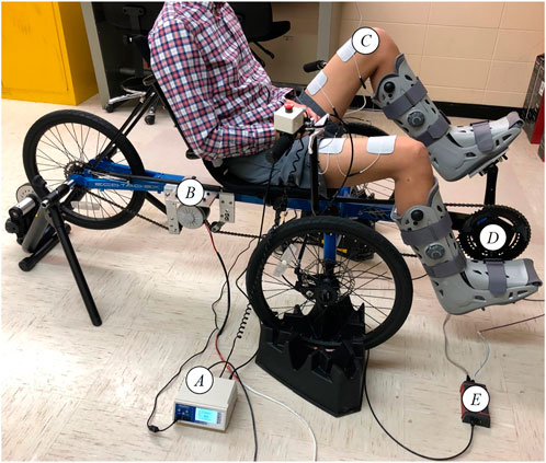
FIGURE 2. Motorized FES-cycling test bed. (A) Current-controlled muscle stimulator. (B) Brushed DC motor. (C) Surface Electrodes. (D) Power meter and encoder. (E) Torque Analysis Box.
5.2 Experimental protocol and control gains selection
A pretrial was performed at the same constant cadence as in the cycling experiments to record passive torque data τpassive used in (Eq. 4) for each participant without applying FES. The desired cadence trajectory
5.3 Tracking results
Table 1 summarizes the root-mean-squared (RMS) cadence error, average of the instantaneous cadence error, and average of the integral torque errors for all subjects and their corresponding gain parameters implemented in (Eq. 20). The experimental results were analyzed starting at t = T2, which is the time the system reached the desired steady-state cadence and the closed-loop muscle and motor controllers were activated. The kinematic tracking performance for participant S1 is illustrated in Figure 3, where the desired cadence is depicted in blue and the actual cadence is depicted in red. The torque tracking error eτ is presented in Figure 4, which remains bounded during the experiment. The torque tracking performance is illustrated in Figure 5, where the desired torque is depicted in light blue, the estimated active torque is depicted in red, and the average estimated active torque with a moving window of 5 s is depicted in solid blue. The average estimated active torque illustrates the evolution of the torque produced by muscles during the experiment, which is an indirect measure of muscle fatigue (i.e., naturally the torque produced by muscles decay due to FES-induced fatigue). Figure 6 shows the desired torque estimation error ef (also referred as the finite-time tracking error) across each crank cycle for different combinations of the gain parameters in (Eq. 20). Figure 7 shows the electric motor input command ue and the muscle stimulation inputs um for both legs in during the last 5 s of a cycling trial.
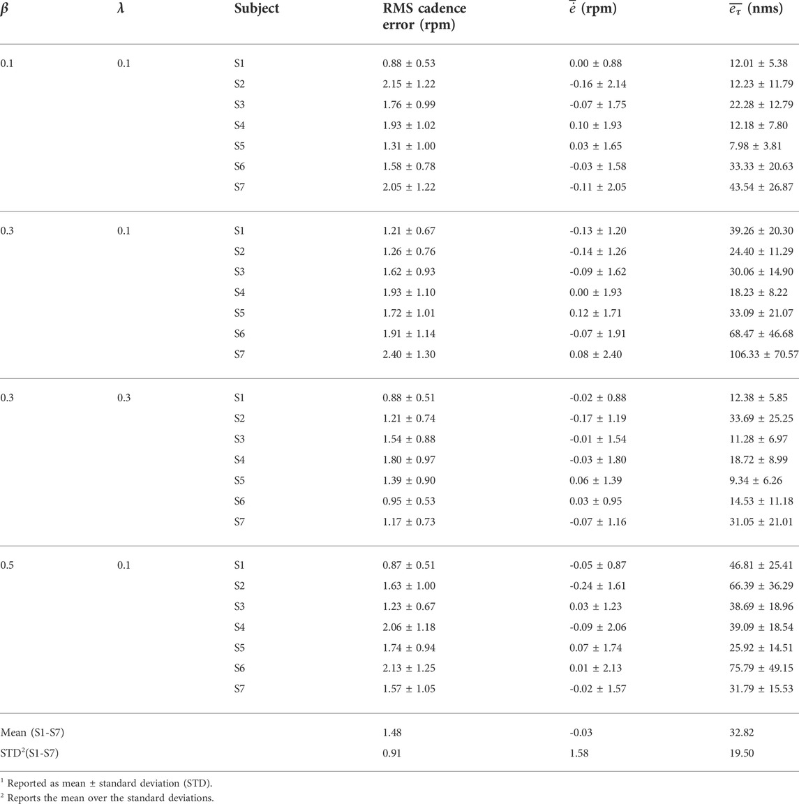
TABLE 1. Tracking results for each participant1: RMS cadence tracking error, average of cadence tracking error
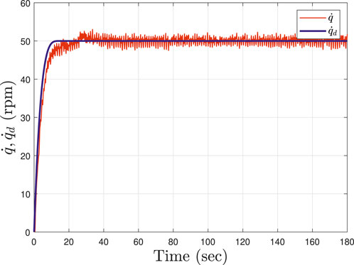
FIGURE 3. Cadence tracking performance depicted for Subject 1 (S1). The cadence trajectory smoothly approached a steady speed (50 RPM) until t = 15 with motor only. Then, within the interval t = [15, 25], FES was integrated and set to um = 40μs. The closed-loop finite-time and muscle torque controllers were activated at t = 25 and remained active until the end of the experiment t = 180. The blue curve illustrates the desired cadence and the red curve shows the actual cadence. The gain parameters in (Eq. 20) are selected as β = 0.3 and λ = 0.3.
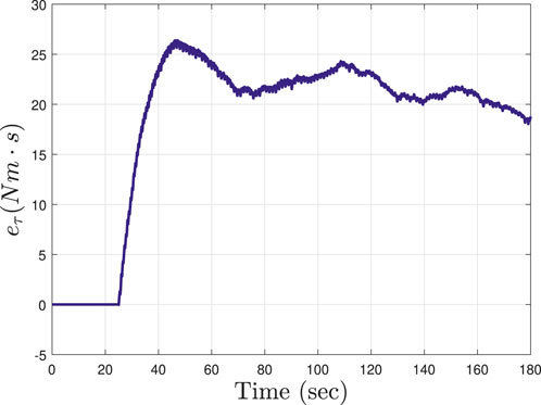
FIGURE 4. The integral-like torque tracking error eτ in (Eq. 22) is depicted for Subject 4 (S4) during the cycling trial with gain parameters in (Eq. 20) selected as β = 0.3 and λ = 0.1. The tracking error starts to be computed and integrated at t = 25.
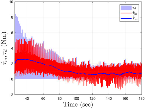
FIGURE 5. Torque tracking performance for Subject 4 (S4) during the cycling trial with gain parameters in (Eq. 20) selected as β = 0.1 and λ = 0.1. The light blue curve illustrates the desired torque τd and the red curve shows the estimated active torque
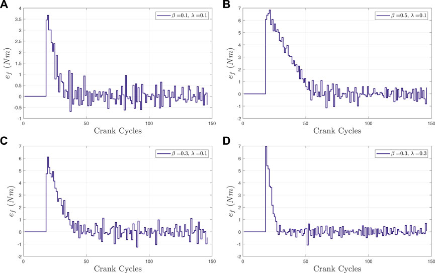
FIGURE 6. The desired torque estimation error ef, i.e., the discrete finite-time tracking error, is depicted for Subject 4 (S4) using four different gain parameter combinations in (Eq. 20) corresponding to the four cycling trials. (A,C,B) figures implement λ = 0.1 with β = 0.1, 0.3, 0.5, respectively, depicting the differences in decay rate after the initial peak. (C,D) figures also provide a basis for comparison between for λ = 0.1 and λ = 0.3 for β = 0.3 for illustrating the differences in decay rate following the initial peak.
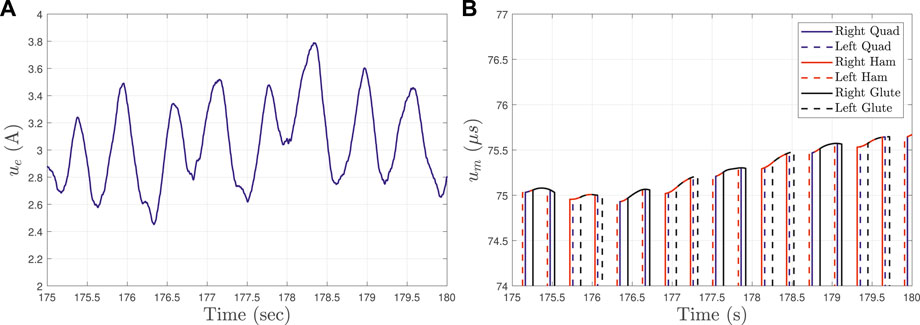
FIGURE 7. Electric motor and muscle stimulation inputs for Subject 1 (S1) during a 5-s window in the cycling trial with gain parameters in (Eq. 20) selected as β = 0.5 and λ = 0.1. The (A) shows the motor current computed by ue. The (B) depicts the pulse widths generated by um and applied to the quadriceps, hamstrings, and gluteus muscle groups for the left and right legs.
5.4 Statistical analysis
Friedman tests were performed at a significance level of α = 0.05 to test for statistically significant differences in tracking performance between the four cycling trials (i.e., four groups) each with different gain parameters as reported in Table 1. The Friedman tests on the response of the four cycling trials indicated that there were no statistically significant differences in the RMS cadence error (p-value = 0.1053) and mean cadence tracking error (p-value = 0.9043). Alternatively, a Friedman test indicated that there was a statistically significant difference between the four cycling trials in the mean torque tracking error (p-value = 0.0134).
6 Discussion
The experimental results demonstrate the feasibility of the developed controllers in (Eqs 13, 24) to track the desired cadence with an electric motor and torque trajectory by applying FES to activate lower limb muscles. The finite-time control algorithm developed in (Eqs 19, 20) adjusts the torque demand in real-time to cope and capture the rider’s time-varying ability to generate active torque. As depicted in Figure 3, the developed motor cadence controller is able to maintain the rider’s speed within a range of less than ±1 RPM. In Figure 4, the integral torque tracking error remains bounded during the cycling trial showing a feasible interaction between the desired torque demand (computed by the finite-time torque algorithm) and the active torque produced by muscles, which depicted in Figure 5. The developed cadence controller yields an average cadence tracking error of −0.03 ± 1.58 RPM across all participants. Cadence tracking performance is influenced by the interaction with the muscle torque controller. Thus, the motor cadence (presented in Figure 7) compensates for the active torque generated by muscles, which act as a disturbance in the cadence control loop. The influence of the muscle torque into the cadence tracking objective can be quantified by the RMS cadence error included in Table 1.
The developed torque tracking controller achieves an average torque tracking error of 32.82 ± 19.50 Nms across all participants. As depicted in Figure 4, the integral-like torque tracking signal eτ started to integrate the error at t = T2 = 25, when the torque tracking controller is activated. The torque tracking error started to build up at the beginning (e.g., up to approximately 45 s) since the finite-time controller was adjusting the desired torque to capture the rider’s ability to generate active torque (i.e., the finite-time controller leverages estimates of the active muscle torque
Stability is guaranteed by the developed stability analyses and illustrated during the cycling trials despite muscle input switching and the nonlinear cycle-rider dynamics. A challenge for the implementation of FES-cycling experiments is related to the muscle activation dynamics. The active torque generated by FES-induced muscle contractions is influenced by the inherent muscle electromechanical delay (EMD). The time-varying EMD is approximately 100–300 ms Downey et al. (2017) and degrades the muscle torque tracking performance. A recent study has developed an input delay compensator to inject a delay-free input in the closed-loop error system to compensate for the muscle input delay Alibeji et al. (2018). However, constructive delayed control compensation requires additional control design and stability analysis, which is beyond the scope of this paper. In this paper, the motivation was to adjust the desired torque trajectory using the finite-time controller leveraging estimates of muscle active torque (thus capturing the muscle activation dynamics) to improve the cycling tracking performance.
The controllers in (Eqs 13, 24) include sliding-mode control terms to compensate for model uncertainty and disturbances in the FES-cycling dynamics to guarantee exponential and GUUB tracking, respectively. However, discontinuous control leverages high frequency that can accelerate the rate of muscle fatigue and lead to potential chattering effects. Future work includes the design of adaptive-based learning controllers to estimate the critical parameters in the model and thus mitigate the use of sliding-mode control techniques.
The finite-time control technique enables the tuning of the desired torque trajectory (i.e., the torque peak amplitude) by selecting the gain parameters β, λ in (Eq. 20) to tune the controller’s rate of convergence and the range of the update law in (Eq. 19). Figure 6 presents the performance of the finite-time controller during the four cycling trials for participant S4. The rate of convergence in experiments can be tuned by tuning the control gains in (Eq. 20) as proven in the stability analysis in Theorem 2. In Figure 6, the number of crank cycles needed to reduce the initial peak error and drive error ef to reach a steady error are around 30, 40, and 55 for β = 0.1, 0.3, 0.5, respectively with a fixed λ = 0.1 (as depicted in the top left, bottom left, and top right figures, respectively). For a fixed value of β = 0.3, it takes around 30 crank cycles to reach a steady error with λ = 0.3 (bottom right figure) and around 40 crank cycles to reach a steady error with λ = 0.1 (bottom left figure). The experimental results demonstrate that the developed finite-time controller has the ability to adjust the rate of convergence of desired torque trajectory, which validates the result in the stability analysis during real-time cycling experiments.
The statistical analysis in Section 5.4 indicates that the tuning of finite-time control parameters in (Eq. 20) yields a statistically significant difference in torque tracking, but not in cadence tracking. This is an expected result since the electric motor is controlled to independently regulate the cadence performance with fixed control gains in (Eq. 13) across cycling trials for all participants. Alternatively, the finite-time controller exploits the rider’s torque data and generates the desired active torque trajectory. Thus, changing the control parameters β, λ in (Eq. 20) across the cycling trials yields significant differences in the torque tracking performance quantified by the mean torque tracking error
The obtained cycling performance in seven able-able-bodied individuals shows the feasibility of the developed cadence and torque tracking controllers to account for the differences in leg function (e.g., muscle strength, muscle mass, etc.) and achieve satisfactory pedaling rates. The control strategy holds the potential to improve rehabilitative cycling in individuals with different levels of lower-limb function and mobility since each individual will inherently need a different level of assistance. In particular, the controller exploits estimates of the active muscle torque to capture the rider’s time-varying ability for power tracking. This control feature is beneficial for FES-cycling and rehabilitation applications to customize the desired trajectories in real-time. Future work includes the implementation of the developed cycling strategy in individuals with movement disorders such as people with chronic SCI who could benefit from the lower-limb exercise. Since the control method is able to adapt the torque demand in real-time, it is envisioned that long-duration cycling trials could be implemented without the need to manually adjust the torque demand and prevent early termination of the cycling experiment.
7 Conclusion
Motorized FES-cycling combines the benefits of FES and the assistance provided by an electrical motor to achieve consistent, stable lower-limb motion. This paper developed and implemented power tracking controllers and demonstrated their feasibility in cycling experiments. A cadence controller is designed for the motor to track a desired constant cadence. FES is applied to the lower-limb muscle groups using an integral-like torque tracking error signal. A discrete finite-time algorithm is developed to generate the desired torque trajectory based on input-output data leveraging estimates of the rider’s active muscle torque. Thus, the finite-time control method capture the rider’s ability to produce active torque in real time cycling experiments. Lyapunov-based stability analyses are presented to guarantee an exponential cadence tracking and a GUUB torque tracking results. A discrete-time Lyapunov-based stability analysis is used to ensure the finite-time algorithm that generates the desired torque trajectory is Hölder continuous and convergence is obtained in a finite number of crank cycles. Experimental results in seven able-bodied individuals are obtained during four cycling trials. Each cycling trial implemented a different combination of the gain parameters of the finite-time torque algorithm. As shown in the stability analysis, tuning the gain parameters in the finite-time algorithm resulted in changes in the rate of convergence quantified in the number of crank cycles. Future work includes the implementation of cycling experiments with people with SCI. Future control innovations include designing controllers that compensate for the EMD and explicitly compensate for muscle fatigue during power tracking cycling experiments.
Data availability statement
The raw data supporting the conclusion of this article will be made available by the authors, without undue reservation.
Ethics statement
The studies involving human participants were reviewed and approved by Institutional Review Board at Syracuse University (email: b3JpcEBzeXIuZWR1). The patients/participants provided their written informed consent to participate in this study. Written informed consent was obtained from the individual(s) for the publication of any potentially identifiable images or data included in this article.
Author contributions
Conceptualization of the paper, C-HC and JC; methodology including control design and conducting experiments, C-HC and JC; writing of the original draft preparation, C-HC and JC; writing-review and editing, VD and AS; graphics visualization, C-HC and JC. All authors have read and approved the submitted version.
Funding
This research is partially supported by the Collaboration for Unprecedented Success and Excellence (CUSE) Grant Program at Syracuse University.
Conflict of interest
The authors declare that the research was conducted in the absence of any commercial or financial relationships that could be construed as a potential conflict of interest.
Publisher’s note
All claims expressed in this article are solely those of the authors and do not necessarily represent those of their affiliated organizations, or those of the publisher, the editors and the reviewers. Any product that may be evaluated in this article, or claim that may be made by its manufacturer, is not guaranteed or endorsed by the publisher.
Footnotes
1The servo drive was provided in part by the sponsorship of Advanced Motion Controls.
2Surface electrodes for the study were provided compliments of Axelgaard Manufacturing Co., Ltd.
References
Alibeji, N. A., Molazadeh, V., Moore-Clingenpeel, F., and Sharma, N. (2018). A muscle synergy-inspired control design to coordinate functional electrical stimulation and a powered exoskeleton: Artificial generation of synergies to reduce input dimensionality. IEEE Control Syst. 38, 35–60. doi:10.1109/mcs.2018.2866603
Alibeji, N., Kirsch, N., and Sharma, N. (2017). An adaptive low-dimensional control to compensate for actuator redundancy and FES-induced muscle fatigue in a hybrid neuroprosthesis. Control Eng. Pract. 59, 204–219. doi:10.1016/j.conengprac.2016.07.015
Bellman, M. (2015). “Control of cycling induced by functional electrical stimulation: A switched systems theory approach,”. Ph.D. thesis.
Bellman, M. J., Cheng, T. H., Downey, R. J., and Dixon, W. E. (2014). “Cadence control of stationary cycling induced by switched functional electrical stimulation control,” in Proceedings of the IEEE Conference on Decision and Control, Los Angeles, CA, USA, 15-17 December 2014, 6260–6265. doi:10.1109/CDC.2014.7040370
Bellman, M. J., Cheng, T. H., Downey, R. J., Hass, C. J., and Dixon, W. E. (2016). Switched control of cadence during stationary cycling induced by functional electrical stimulation. IEEE Trans. Neural Syst. Rehabil. Eng. 24, 1373–1383. doi:10.1109/TNSRE.2015.2500180
Bellman, M. J., Downey, R. J., Parikh, A., and Dixon, W. E. (2017). Automatic control of cycling induced by functional electrical stimulation with electric motor assistance. IEEE Trans. Autom. Sci. Eng. 14, 1225–1234. doi:10.1109/TASE.2016.2527716
Bhat, S. P., and Bernstein, D. S. (2000). Finite-time stability of continuous autonomous systems. SIAM J. Control Optim. 38, 751–766. doi:10.1137/S0363012997321358
Casas, J., Chang, C.-H., and Duenas, V. H. (2020). “Motorized and functional electrical stimulation induced cycling via switched adaptive concurrent learning control,” in Proceedings of the ASME 2020 Dynamic Systems and Control Conference, Pittsburgh, PA, Oct 5-7, 8.
Chang, C.-H., Casas, J., Brose, S. W., and Duenas, V. H. (2022). Closed-loop torque and kinematic control of a hybrid lower-limb exoskeleton for treadmill walking. Front. Robot. AI 8, 702860. doi:10.3389/frobt.2021.702860
Chang, C. H., Duenas, V. H., and Sanyal, A. (2020). “Model free nonlinear control with finite-time estimation applied to closed-loop electrical stimulation induced cycling,” in Proceedings of the American Control Conference, Denver, CO, USA, 01-03 July 2020, 5182–5187. doi:10.23919/ACC45564.2020.9147327
Chang, C. H., and Duenas, V. H. (2019). “Switched motorized and functional electrical stimulation cycling controllers for power tracking,” in 2019 IEEE 58th Conference on Decision and Control (CDC), Nice, France, 11-13 December 2019, 1436–1441. doi:10.1109/CDC40024.2019.9029409
Chang, S. R., Nandor, M. J., Li, L., Kobetic, R., Foglyano, K. M., Schnellenberger, J. R., et al. (2017). A muscle-driven approach to restore stepping with an exoskeleton for individuals with paraplegia. J. Neuroeng. Rehabil. 14, 48. doi:10.1186/s12984-017-0258-6
Cousin, C. A., Duenas, V. H., Rouse, C. A., Bellman, M. J., Freeborn, P., Fox, E. J., et al. (2020). Closed-loop cadence and instantaneous power control on a motorized functional electrical stimulation cycle. IEEE Trans. Control Syst. Technol. 28, 2276–2291. doi:10.1109/TCST.2019.2937725
Cousin, C. A., Duenas, V. H., Rouse, C. A., and Dixon, W. E. (2019). Admittance control of motorized functional electrical stimulation cycle. IFAC-PapersOnLine 51, 272–277. doi:10.1016/j.ifacol.2019.01.040
Doucet, B. M., Lam, A., and Griffin, L. (2012). Neuromuscular electrical stimulation for skeletal muscle function. Yale J. Biol. Med. 85, 201–215.
Downey, R. J., Merad, M., Gonzalez, E. J., and Dixon, W. E. (2017). The time-varying nature of electromechanical delay and muscle control effectiveness in response to stimulation-induced fatigue. IEEE Trans. Neural Syst. Rehabil. Eng. 25, 1397–1408. doi:10.1109/TNSRE.2016.2626471
Duenas, V. H., Cousin, C. A., Ghanbari, V., Fox, E. J., and Dixon, W. E. (2020). Torque and cadence tracking in functional electrical stimulation induced cycling using passivity-based spatial repetitive learning control. Automatica 115, 108852. doi:10.1016/j.automatica.2020.108852
Duenas, V. H., Cousin, C. A., Parikh, A., Freeborn, P., Fox, E. J., Dixon, W. E., et al. (2019). Motorized and functional electrical stimulation induced cycling via switched repetitive learning control. IEEE Trans. Control Syst. Technol. 27, 1468–1479. doi:10.1109/TCST.2018.2827334
Farhoud, A., and Erfanian, A. (2014). Fully automatic control of paraplegic FES pedaling using higher-order sliding mode and fuzzy logic control. IEEE Trans. Neural Syst. Rehabil. Eng. 22, 533–542. doi:10.1109/TNSRE.2013.2296334
Ferrarin, M., and Pedotti, A. (2000). The relationship between electrical stimulus and joint torque: A dynamic model. IEEE Trans. Rehabil. Eng. 8, 342–352. doi:10.1109/86.867876
Field-Fote, E. C., and Roach, K. E. (2011). Influence of a locomotor training approach on walking speed and distance in people with chronic spinal cord injury: A randomized clinical trial. Phys. Ther. 91, 48–60. doi:10.2522/ptj.20090359
Fischer, N., Kamalapurkar, R., and Dixon, W. E. (2013). LaSalle-Yoshizawa corollaries for nonsmooth systems. IEEE Trans. Autom. Contr. 58, 2333–2338. doi:10.1109/TAC.2013.2246900
Garg, K., Bobade, P., and Panagou, D. (2018). Finite-time stability of adaptive parameter estimation and control. arXiv preprint arXiv:1811.11151.
Garg, K., and Panagou, D. (2019). Finite-time stability of switched and hybrid systems. arXiv preprint arXiv:1901.08513.
Ghanbari, V., Duenas, V. H., Antsaklis, P. J., and Dixon, W. E. (2019). Passivity-based iterative learning control for cycling induced by functional electrical stimulation with electric motor assistance. IEEE Trans. Control Syst. Technol. 27, 2287–2294. doi:10.1109/TCST.2018.2854773
Guay, M., and Benosman, M. (2021). Finite-time extremum seeking control for a class of unknown static maps. Int. J. Adapt. Control Signal Process. 35, 1188–1201. doi:10.1002/acs.3123
Haddad, W. M., Nersesov, S. G., and Du, L. (2008). “Finite-time stability for time-varying nonlinear dynamical systems,” in Proceedings of the American Control Conference, Seattle, WA, 11-13 June 2008, 4135–4139. doi:10.1109/ACC.2008.4587141
Ho, C. H., Triolo, R. J., Elias, A. L., Kilgore, K. L., DiMarco, A. F., Bogie, K., et al. (2014). Functional electrical stimulation and spinal cord injury. Phys. Med. Rehabilitation Clin. N. Am. 25, 631–654. doi:10.1016/j.pmr.2014.05.001
Hong, E. K., Gorman, P. H., Forrest, G. F., Asselin, P. K., Knezevic, S., Scott, W., et al. (2020). Mobility skills with exoskeletal-assisted walking in persons with SCI: Results from a three center randomized clinical trial. Front. Robot. AI 7, 93. doi:10.3389/frobt.2020.00093
Hornby, T. G., Reisman, D. S., Ward, I. G., Scheets, P. L., Miller, A., Haddad, D., et al. (2020). Clinical practice guideline to improve locomotor function following chronic stroke, incomplete spinal cord injury, and brain injury. J. Neurol. Phys. Ther. 44, 49–100. doi:10.1097/NPT.0000000000000303
Hui, Q., Haddad, W. M., and Bhat, S. P. (2009). Semistability, finite-time stability, differential inclusions, and discontinuous dynamical systems having a continuum of equilibria. IEEE Trans. Autom. Contr. 54, 2465–2470. doi:10.1109/TAC.2009.2029397
Hunt, K. J., Stone, B., Negård, N. O., Schauer, T., Fraser, M. H., Cathcart, A. J., et al. (2004). Control strategies for integration of electric motor assist and functional electrical stimulation in paraplegic cycling: Utility for exercise testing and mobile cycling. IEEE Trans. Neural Syst. Rehabil. Eng. 12, 89–101. doi:10.1109/TNSRE.2003.819955
Kawai, H., Bellman, M. J., Downey, R. J., and Dixon, W. E. (2019). Closed-loop position and cadence tracking control for FES-cycling exploiting pedal force direction with antagonistic biarticular muscles. IEEE Trans. Control Syst. Technol. 27, 730–742. doi:10.1109/TCST.2017.2771727
Kirshblum, Steven, and Lin, V. W. (2018). Spinal cord medicine. New York: Springer Publishing Company.
Kressler, J., and Domingo, A. (2019). Cardiometabolic challenges provided by variable assisted exoskeletal versus overground walking in chronic motor-incomplete paraplegia: A case series. J. Neurol. Phys. Ther. 43, 128–135. doi:10.1097/NPT.0000000000000262
Kressler, J., Wymer, T., and Domingo, A. (2018). Respiratory, cardiovascular and metabolic responses during different modes of overground bionic ambulation in persons with motor-incomplete spinal cord injury: A case series. J. Rehabil. Med. 50, 173–180. doi:10.2340/16501977-2281
Lewis, L., Dawson, D., M., and Abdallah, C. T. (2004). Robot manipulator control theory and practice. New York: Marcel Dekker. doi:10.1063/1.1759088
Lynch, C. L., and Popovic, M. R. (2008). Functional electrical stimulation. IEEE Control Syst. Mag. 28, 40–50. doi:10.1109/MCS.2007.914689
McCabe, J., Monkiewicz, M., Holcomb, J., Pundik, S., and Daly, J. J. (2015). Comparison of robotics, functional electrical stimulation, and motor learning methods for treatment of persistent upper extremity dysfunction after stroke: A randomized controlled trial. Archives Phys. Med. Rehabilitation 96, 981–990. doi:10.1016/j.apmr.2014.10.022
Nataraj, R., Audu, M. L., and Triolo, R. J. (2017). Restoring standing capabilities with feedback control of functional neuromuscular stimulation following spinal cord injury. Med. Eng. Phys. 42, 13–25. doi:10.1016/j.medengphy.2017.01.023
Nersesov, S. G., and Haddad, W. M. (2008). Finite-time stabilization of nonlinear impulsive dynamical systems. Nonlinear Anal. Hybrid. Syst. 2, 832–845. doi:10.1016/j.nahs.2007.12.001
Paden, B. E., and Sastry, S. S. (1987). A calculus for computing filippov’s differential inclusion with application to the variable structure control of robot manipulators. IEEE Trans. Circuits Syst. 34, 73–82. doi:10.1109/TCS.1987.1086038
Peckham, P. H., and Knutson, J. S. (2005). Functional electrical stimulation for neuromuscular applications. Annu. Rev. Biomed. Eng. 7, 327–360. doi:10.1146/annurev.bioeng.6.040803.140103
Poveda, J. I., and Krstic, M. (2020). “Fixed-time extremum seeking,” in 2020 American Control Conference (ACC), Denver, CO, USA, 01-03 July 2020, 2838–2843.
Reed, B. (1997). The physiology of neuromuscular electrical stimulation. Pediatr. Phys. Ther. 9, 96–102. doi:10.1097/00001577-199700930-00002
Romero, O., and Benosman, M. (2021). Time-varying continuous-time optimisation with pre-defined finite-time stability. Int. J. Control 94, 3237–3254. doi:10.1080/00207179.2020.1756415
Rouse, C. A., Parikh, A., Duenas, V., Cousin, C., and Dixon, W. E. (2018). A switched systems approach based on changing muscle geometry of the biceps brachii during functional electrical stimulation. IEEE Control Syst. Lett. 2, 73–78. doi:10.1109/CDC.2016.7798450
Sale, P., Russo, E. F., Scarton, A., Calabrò, R. S., Masiero, S., Filoni, S., et al. (2018). Training for mobility with exoskeleton robot in spinal cord injury patients: A pilot study. Eur. J. Phys. Rehabil. Med. 54, 745–751. doi:10.23736/S1973-9087.18.04819-0
Sanyal, A. K. (2021). Discrete-time data-driven control with Hölder-continuous real-time learning. Int. J. Control, 1–13. doi:10.1080/00207179.2021.1901993
Schauer, T., Negård, N. O., Previdi, F., Hunt, K. J., Fraser, M. H., Ferchland, E., et al. (2005). Online identification and nonlinear control of the electrically stimulated quadriceps muscle. Control Eng. Pract. 13, 1207–1219. doi:10.1016/j.conengprac.2004.10.006
Sharma, N., Stegath, K., Gregory, C. M., and Dixon, W. E. (2009). Nonlinear neuromuscular electrical stimulation tracking control of a human limb. IEEE Trans. Neural Syst. Rehabil. Eng. 17, 576–584. doi:10.1109/TNSRE.2009.2023294
Sheng, Z., Sharma, N., and Kim, K. (2020). Quantitative assessment of changes in muscle contractility due to fatigue during NMES: An ultrasound imaging approach. IEEE Trans. Biomed. Eng. 67, 832–841. doi:10.1109/TBME.2019.2921754
Keywords: finite-time control, nonlinear control systems, Lyapunov methods, functional electrical stimulation, cycling
Citation: Chang C-H, Casas J, Sanyal AK and Duenas VH (2022) Motorized FES-cycling and closed-loop nonlinear control for power tracking using a finite-time stable torque algorithm. Front. Control. Eng. 3:910126. doi: 10.3389/fcteg.2022.910126
Received: 31 March 2022; Accepted: 07 July 2022;
Published: 05 August 2022.
Edited by:
Christodoulos Keliris, University of Cyprus, CyprusReviewed by:
Pablo Borja, Delft University of Technology, NetherlandsOmer Saleem, National University of Computer and Emerging Sciences, Pakistan
Copyright © 2022 Chang, Casas, Sanyal and Duenas. This is an open-access article distributed under the terms of the Creative Commons Attribution License (CC BY). The use, distribution or reproduction in other forums is permitted, provided the original author(s) and the copyright owner(s) are credited and that the original publication in this journal is cited, in accordance with accepted academic practice. No use, distribution or reproduction is permitted which does not comply with these terms.
*Correspondence: Victor H. Duenas, dmhkdWVuYXNAc3lyLmVkdQ==