Design to Robotic Assembly: An Exploration in Stacking
 Yu-Chou Chiang
 Henriette Bier
 Sina Mostafavi1,2
- 1Faculty of Architecture and the Built Environment, Delft University of Technology, Delft, Netherlands
- 2Dessau Institute of Architecture, Anhalt University of Applied Sciences, Dessau, Germany
The Design-to-Robotic-Assembly project presented in this paper showcases an integrative approach for stacking architectural elements with varied sizes in multiple directions. Several processes of parametrization, structural analysis, and robotic assembly are algorithmically integrated into a Design-to-Robotic-Production method. This method is informed by the systematic control of density, dimensionality, and directionality of the elements while taking environmental, functional, and structural requirements into consideration. It is tested by building a one-to-one prototype, which is presented and discussed in the paper with respect to the development and implementation of the computational design workflow coupled with robotic kinematic simulation that is enabling the materialization of a multidirectional and multidimensional assembly system.
Introduction
In the last decades, automated fabrication and robotic assembly have experienced an exponential growth in practically every type of manufacturing and assembly process (International Federation of Robotics, 2016). In this context, mass production has been achieved through fully or semi-automated production and assembly processes, which have persistently improved the productivity in the manufacturing sector. In strong contrast, the productivity in architecture and building construction has barely increased (Barbosa et al., 2017). Thus, it is essential to explore and establish novel materialization methods by developing Design-to-Robotic-Production (D2RP) processes that integrate subtractive, additive and formative techniques of robotic production in architecture (Mostafavi and Bier, 2016; Bier, 2017). Considering the scale of buildings, it is crucial to expand production space beyond the size of the machinery. Therefore, assembly is the essential step toward the completion of robotically supported workflow from design to construction.
Even though measures to improve productivity in architecture, engineering, and construction industry have been identified, implementation still lacks the in-depth integration between disciplines with latest digital and robotic technology. In this context, D2RP and Assembly (D2RP&A) processes introduce a trans-disciplinary approach that integrates computational design with robotic production and assembly, which are still seen as segregated fields of knowledge and expertise (Capro and Kohler, 2014; Bier and Mostafavi, 2015; Bier, 2017). This paper elaborates on the materialization of a fragment derived from a housing unit, conceptually developed during a D2RP&A design studio held at Dessau Institute of Architecture (DIA), as a D2RP&A case study focused on robotic staking. It first, reviews assembly approaches relevant to robotic production in the background section. Subsequently, it introduces schematic and materialization design approach. Then, the assembly method with 6-axis industrial robot is illustrated. Finally, the conclusion of presented research with outlook into the future is drawn.
Background
Robotic assembly is the essential step toward the completion of robotically supported workflow from design to construction. Acquired experience indicates that in order to obtain a realistic design, one should consider not only design aspects but also materialization (Bier and Mostafavi, 2015). Completing the research domain by including assembly implies not to merely focus on combing separate components together but develop a holistic design to construction scheme. This includes two processes: The decomposition of the whole into manufacturable components in the design phase, and the aggregation of the components in the construction stage.
There are numerous researchers devoting themselves investigating the interrelation between design and robotic production. By identifying the differences between the various schemes, these assembly methods can be categoriesed by:
Components' Uniqueness Level
Assemblages are built up from identical materials and types of components, or with components that are unique.
For the assembly with identical materials, the robotic brick laying projects developed at ETH Zurich (Bonwetsch et al., 2006; Bärtschi et al., 2010) and 3D printing with fused filament fabrication fall into this category. Only after the brick or droplet of filament is laid down or deposited in a specific position, it receives an unique identity within the whole assemblage due to its position.
On the other end of the spectrum, each component is unique. For instance, in the ICD/ITKE Research Pavilion 2011 in Stuttgart (Menges, 2012) and the Armadillo Vault at Venice Architecture Biennale 2016 (Van Mele et al., 2016), the materials (i.e., timber and marble) were shaped into unique components. Then, in the assembly process, each component had to be picked in a certain order to be then installed in its position one by one. Although the assembly was implemented manually in these two cases, the tenon and mortise for assembly were prepared with CNC machinery beforehand.
Assemblages' Product/Facilitator Level
Assemblages can serve as final products (e.g., the three cases mentioned above) or temporary facilitators.
For instance, formwork for site-cast concrete is a facilitatory assemblage. The assembled formwork serves as a shaping container for the freshly poured concrete. The assemblage plays a role in the construction stage, but is removed before the product goes into the operation stage. Similarly, a falsework of a vault is also seen as a facilitatory assemblage.
Sometimes, assemblages can serve as both. For instance, in the project of stay-in-place robotically sprayed foam formwork developed at MIT (Keating et al., 2017), the foam formwork was assembled with an identical material (foam). The researchers proposed that the printed foam serves as a formwork when shotcrete is applied on it. After the concrete hardens, the formwork is not being removed; it stays there and serves as thermal insulation. The multi-purposefulness of the foam makes it act as both product and facilitator.
Assemblages' Continuous/Discrete Level
Robotic staking as an additive construction method has been extensively explored in architecture (Bonwetsch et al., 2006; Gramazio et al., 2010; Pérez, 2017). According to Retsin et al. (2017), two types of connections and thus approaches were identified: continuous and discrete. The continuous approach presents gradually differentiated parameterized patterns implemented on relatively simple topologies such as walls, while the discrete approach achieves more complex topologies. The proposed D2RP&A approach combines the advantages of both known approaches by exploiting the dimensional flexibility of the continuous approach as well as the spatial freedom and multi-sized hybridity of the discrete approach.
Schematic Design for D2RP&A
The D2RP&A stacking construction method is implemented on a fragment of a housing unit, which has a free-formed structural envelope with integrated furniture, environmentally informed porosity, and locally controlled climate employing smart devices. The overall geometry is generated by mapping the movement of the human body in 3D space (Figure 1). In a next step, the required furniture facilitating indoor activities is integrated into the overall geometry serving as a schematic building skin. Thus, the skin is not a simple curved envelope, but a structure with variable thickness and differentiated degrees of porosity. The various thicknesses facilitate functionalities for diverse indoor activities, while porosity accommodates openings for views, light, ventilation, doors, and/or host smart devices for climate control (Figures 2, 3).
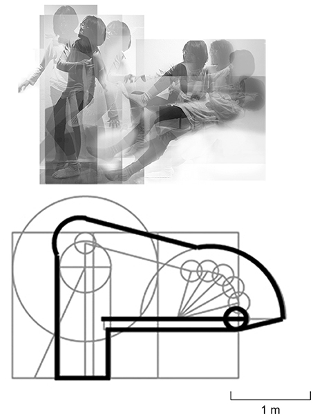
Figure 1. The mapping of user movements in space used to design the student-housing unit.
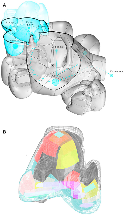
Figure 2. Overall geometry obtained from movement mapping (A) with climate requirements mapped on a fragment (B).
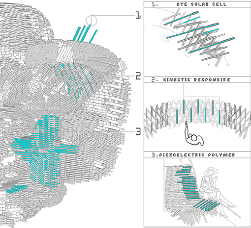
Figure 3. Integration of smart devices such as dye-sensitized solar cells, kinetic responsive shading, piezoelectric polymer, and Peltier elements.
A fragment of the 3D overall geometry is selected to identify climate requirements (Figure 2), which are then color-coded: Red patches are used for radiation, orange for sun path, yellow for natural lighting, green for views, purple for heating-cooling, and blue for artificial lighting. In addition to environmental requirements, structural analysis is also performed in order to identify the required density of the structural material.
Materialization Design for D2RP&A
In this design, two types of components are involved: Smart devices and structural elements. The smart devices are installed to regulate the environmental quality, while the structural elements are stacked in various densities reflecting the previous environmental and structural analysis.
The integration of smart devices required Design-to-Robotic-Operation (D2RO) approaches implying strategies to customize indoor climate use by taking into account short-, mid-, and long-term changes in the use of space and respective individual needs based (not on average but) real-time ambient and spatial data. Several smart devices were distributed along the mapped areas as for instance dye-sensitized solar cells and piezoelectric components that harvest and convert solar radiation and human kinetic energy into electricity.
Regarding the structural material, the linear elements have two different sizes. Large elements establish the bearing structure, while small elements are used as infill. Where stiff structural material is not required, more bulky elements are substituted by slim elements. Thus, layers are subdivided into sub-layers and the thicknesses of layers and subdivided layers 3:1 and the sectional profiles of the elements are 90/90 mm and 30/30 mm.
Components have similar geometry, which is neither identical nor unique and structural elements span for certain distances in order to allow assembly process without temporary supports. Two different combining methods are applied in different directions. The method within a layer is continuous while the method cross-layer wise is discrete (either 1 layer of 90 mm or 3 layers of 30 mm).
Human Assisted Robotic Stacking
In the production process, a 6-axis robot equipped with a pneumatic gripper is employed to assemble the structural prototype, which consists of linear elements in two sectional profile and various lengths. For construction, the movement of the pneumatic gripper has to be defined from two aspects: The first one is defining the movement between picking and placing positions. The other one is arranging the assembling sequence as to ensure that the assembly is balanced at any moment during the construction phase. Moreover, the collision between the moving element on the gripper and the previously stacked elements is prevented.
For installing one structural element, there are 10 movements involved in the pick and place cycle: (1) Start from origin point to 50 mm above picking position; (2–4) Approach picking position and pick the element up (Figure 4A); (5, 6) Transport the element through the hub to 50 mm above placing position (Figure 4B); (7–10) Approach placing position and release the element and then go back to the origin point (Figure 4C). For the stacking sequence, the essential criterion is to make sure that every element is placed in a stable position. Inevitably, the sequence starts from the very bottom layer. Within each layer, the one that has proper footing is placed before the overhanging one (shown dashed in Figure 5). The elements that need to be placed are fed to the picking dock manually, in the construction of this prototype.
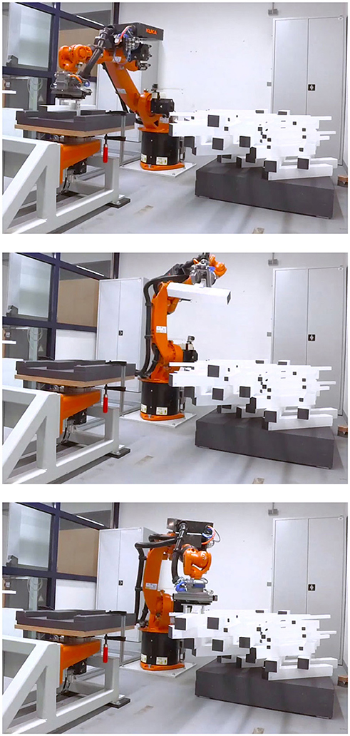
Figure 4. Working path for stacking involved movement sequences such as picking, transporting, and placing.
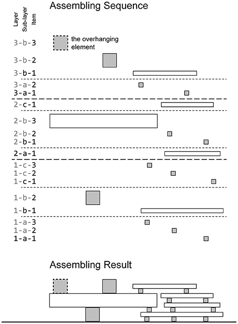
Figure 5. Assembly of layers and sub-layers follows a sequence that is allowing hang over condition and combination of larger and smaller elements.
Furthermore, certain physical constraints are also affecting the arrangement of elements: The spacing between elements should allow the gripper to work and in order to prevent collision between elements, the elements' length (l), width (a), tilting angle (θ), the radius of curvature (ρ) and the distance between the center points (d) should meet the constraint indicated in Figure 6. Since the shell in this case study has a non-uniform thickness, longer and shorter elements are introduced. The length of elements is limited when the orientation of elements is not parallel to each other and the limit of the length is identified with an adjusted distance (d2, shown in Figure 6).
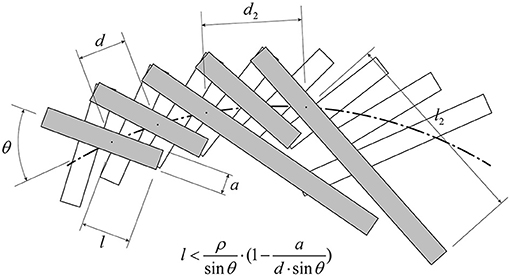
Figure 6. In order to introduce gradual variation in the angles between elements, control collision between elements is established by keeping some of the in-between elements shorter (for instance the fourth white element in the figure) so that more degrees of length variation can be achieved.
Furthermore, the ratio between large and small elements should be an odd integer to 1, in order to keep layering arrangement simple. If the ratio of large to small elements is 3:1, when 3 layers of small elements placed at the side of 1 layer of large elements, the main axis of the elements can be parallel at both top and bottom surfaces. This feature allows that every contact between elements in different layers is cross-wise.
The stacking produces a fragment that has a mild curvature and cantilevers in multiple directions, proving that the two stacking approaches continuous and discrete can be successful combined for not only achieving more variation but also integrate smart devices. Furthermore, the human-assisted robotic staking is the first step toward human-robot collaboration, which is necessary for implementing construction at building scale and needs to be explored further.
Conclusion
Robotic assembly completes the automated workflow from schematic design to physical construction. The D2RP&A process involving stacking of linear elements with focus on the experimental investigation into the generation of free-formed architectural structures proves the potential of assembling linear elements of various sizes and spatial orientation in order to allow integration of structure with climate control. The case study also validates that the robotic stacking method allows building cantilevers of certain spans. The developed D2RP&A methods are expected to streamline the process from design to construction and to make a desired geometrically complex architecture deliverable for a moderate budget. They are expected to increase the productivity in the architecture, engineering and construction industry.
Future steps involve advancing the explored human-assisted robotic production to human-robot collaboration as well as developing assembly logics ranging from plain stacking to interlocking or intertwining elements. Main consideration is that the factory of the future in architecture and building construction employs building components that can be robotically processed, assembled, and operated. Main challenge for the future is the integration of human-robot collaboration with D2RP&A. For instance, by employing laser scanning to capture the current status of building process, an extended feedback-loop between the virtual and the physical environments could be established. Robots may then interact with humans, as for instance, human operators may teach robots to do certain tasks by guiding them with a tool or by hand, while dynamic safety systems are in place, etc. Main consideration is that production and operation of buildings will be in the future robotized and identifying which skills sets are better acquired and executed by humans while others by machines is key to developing interaction scenarios between humans and robots.
Author Contributions
HB has contributed in the role of supervisor of the Ph.D. senior researcher SM and Ph.D. researcher Y-CC, who have co-supervised MSc students involved in this project. Authors developed presented methods with assistance of DIA and TUD students.
Funding
Presented project has been funded by Delft University of Technology and Dessau Institute of Architecture.
Conflict of Interest Statement
The authors declare that the research was conducted in the absence of any commercial or financial relationships that could be construed as a potential conflict of interest.
Acknowledgments
This paper has profited from the contribution of TUD Robotic Building and DIA researchers, tutors, and students. In particular, the authors acknowledge DIA students Arise Wan, Lim Tian Jing, Leong Chee Chung for the development of the student-housing unit as well as its corresponding 1:1 prototyped fragment. Authors also acknowledge the assistance of Marco Gali and Daniel Fischer as MSc students of TUD for contributing in early tests of stacking at DIA.
References
Barbosa, F., Woetzel, J., Mischke, J., Ribeirinho, M. J., Sridhar, M., Parsons, M., et al. (2017). Reinventing Construction: A Route to Higher Productivity. Mckinsey Global Institute. Available online at: https://www.mckinsey.com/industries/capital-projects-and-infrastructure/our-insights/reinventing-construction-through-a-productivity-revolution
Bärtschi, R., Knauss, M., Bonwetsch, T., Gramazio, F., and Kohler, M. (2010). Wiggled brick bond. Adv. Archit. Geom. 2010, 137–147. doi: 10.1007/978-3-7091-0309-8_10
Bier, H. (2017). Robotic Building as Integration of Design-to-Robotic-Production & Operation. SPOOL, [S.l.], v. 4, n. 1, Available online at: https://journals.open.tudelft.nl/index.php/spool/article/view/1908
Bier, H., and Mostafavi, S. (2015). Structural optimization for materially informed design to robotic production processes, Am. J. Eng. Appl. Sci. 8, 549–555. doi: 10.3844/ajeassp.2015.549.555
Bonwetsch, T., Kobel, D., Gramazio, F., and Kohler, M. (2006). “The informed wall: applying additive digital fabrication techniques to architecture. Synthetic landscapes,” in Proceedings of the 25th Annual Conference of the Association for Computer-Aided Design in Architecture (Louisville), 489–495.
Capro, M., and Kohler, M. (2014). “Mario Carop in conversation with Matthias Kohler,” in Fabricate 2014: Negotiating Design and Making, eds F. Gramazio, M. Kohler, and S. Langenberg (London: UCL Press), 12–21.
Gramazio, F., Kohler, M., and Oesterle, S. (2010). Encoding material. Archit. Des. 80, 108–115. doi: 10.1002/ad.1114
International Federation of Robotics (2016). Executive Summary World Robotics 2016 Industrial Robots. Frankfurt am Main: Author. Available online at: https://ifr.org/img/uploads/Executive_Summary_WR_Industrial_Robots_20161.pdf
Keating, S. J., Leland, J. C., Cai, L., and Oxman, N. (2017). Toward site-specific and self-sufficient robotic fabrication on architectural scales. Sci. Rob. 2, eaam8986. doi: 10.1126/scirobotics.aam8986
Menges, A. (2012). Material computation: higher integration in morphogenetic design. Archit. Des. 82, 14–21. doi: 10.1002/ad.1374
Mostafavi, S., and Bier, H. (2016). Materially informed design to robotic production: a robotic 3D printing system for informed material deposition. Rob. Fab. Archit. Art Des. 2016, 338–349. doi: 10.1007/978-3-319-26378-6_27
Pérez, S. F. (2017). “Loss of control: error, glitch, and imperfection in architecture,” in Lineament: Material, Representation and the Physical Figure in Architectural Production, eds G. P. Borden and M. Meredith (London: Routledge).
Retsin, G., García, M. J., and Soler, V. (2017). “Discrete computation for additive manufacturing,” in Fabricate 2017: Rethinking Design and Construction, eds A. Menges, B. Sheil, R. Glynn, and M. Skavara (London: UCL Press), 178–183.
Keywords: Design-to-Robotic-Production, informed materialization, robotic building, robotic assembly, robotic stacking
Citation: Chiang Y-C, Bier H and Mostafavi S (2018) Design to Robotic Assembly: An Exploration in Stacking. Front. Digit. Humanit. 5:23. doi: 10.3389/fdigh.2018.00023
Received: 26 October 2017; Accepted: 21 August 2018;
Published: 15 October 2018.
Edited by:
Andrei Gheorghe, University of Applied Arts Vienna, AustriaReviewed by:
Eran Neuman, Tel Aviv University, IsraelElie J. Gamburg, Kohn Pedersen Fox Associates PC, United States
Copyright © 2018 Chiang, Bier and Mostafavi. This is an open-access article distributed under the terms of the Creative Commons Attribution License (CC BY). The use, distribution or reproduction in other forums is permitted, provided the original author(s) and the copyright owner(s) are credited and that the original publication in this journal is cited, in accordance with accepted academic practice. No use, distribution or reproduction is permitted which does not comply with these terms.
*Correspondence: Yu-Chou Chiang, y.chiang@tudelft.nl
Henriette Bier, h.h.bier@tudelft.nl