Simultaneous Inversion of Layered Velocity and Density Profiles Using Direct Waveform Inversion (DWI): 1D Case
- Department of Earth and Atmospheric Sciences, The University of Houston, Houston, TX, United States
To better interpret the subsurface structures and characterize the reservoir, a depth model quantifying P-wave velocity together with additional rock’s physical parameters such as density, the S-wave velocity, and anisotropy is always preferred by geologists and engineers. Tradeoffs among different parameters can bring extra challenges to the seismic inversion process. In this study, we propose and test the Direct Waveform Inversion (DWI) scheme to simultaneously invert for 1D layered velocity and density profiles, using reflection seismic waveforms recorded on the surface. The recorded data includes primary reflections and interbed multiples. DWI is implemented in the time-space domain then followed by a wavefield extrapolation to downward continue the source and receiver. By explicitly enforcing the wavefield time-space causality, DWI can recursively determine the subsurface seismic structure in a local layer-by-layer fashion for both sharp interfaces and the properties of the layers, from shallow to deep depths. DWI is different from the layer stripping methods in the frequency domain. By not requiring a global initial model, DWI also avoids many nonlinear optimization problems, such as the local minima or the need for an accurate initial model in most waveform inversion schemes. Two numerical tests show the validity of this DWI scheme serving as a new strategy for multi-parameter seismic inversion.
Introduction
Seismic full waveform inversion (FWI), formulated originally by (Lailly, 1983; Tarantola, 1984), is a powerful process in subsurface velocity model building. The goal of FWI is to find a model such that the model-predicted waveforms fit the observed waveforms. Since FWI is an iterative gradient-based method, its success depends on how much the initial model differs from the true model (Virieux and Operto, 2009). The limitation of the iterative FWI scheme was recognized early on by many authors (Gauthier et al., 1986; Tarantola, 1986; Mora, 1987; Bourgeois et al., 1989). Tarantola (2005, p.128) pointed out that the local Fréchet gradient used in FWI was equivalent to the single scattering Born approximation. Therefore the performance of FWI relies on an accurate and long-wavelength initial velocity model in which case the Born approximation is more accurate. As the correspondence between low-frequency seismic data and low-wavenumber/large-scale structures is linear in the Born single scattering (Wu and Zheng, 2014), due to the lack of low-frequency content (<5 Hz) in most reflection seismic data, most developments in FWI have been focusing on how to recover large-scale structural information when low-frequency data are not available. These developments include, for example, the Laplace FWI (Shin and Cha, 2008; Shin and Ha, 2008; Kim et al., 2013), envelope inversion (Wu et al., 2014; Luo and Wu, 2015; Chen et al., 2018), intensity inversion (Liu et al., 2018; Liu et al., 2020), and the FWI using deep learning techniques (Richardson, 2018).
To circumvent the challenges in FWI, we proposed an alternative waveform inversion scheme (Liu and Zheng, 2015; 2017), called the direct waveform inversion (DWI), to invert for subsurface models without the need for a global initial model. DWI combines seismic imaging and velocity model building into one single process. In order to use DWI, it is necessary for the input seismic data to include both free-surface and inter-bed multiples. Using surface recorded reflection seismic data, DWI is able to deliver accurate P-wave velocity inversion results without using a global initial model, for both 1D and 2D layered scalar (i.e., no density variation) models (Zheng and Liu, 2020). Without using a global model, DWI inverts the model from shallow to deep depths. In this regard, DWI is similar to the layer-stripping methods (Claerbout, 1976) and the approach by Goupillaud (1961). However, there are important differences in the methods, in particular the explicit use of the time-space causality in DWI and local inversion in both space and time.
In the current industry, simultaneous inversion of multiple rock physical parameters is one of the state-of-art workflows that can much directly benefit the subsurface reservoir characterization and improve production (Brossier et al., 2009), using surface seismic data. To address the demand of multi-parameter inversion, many FWI methods are developed to invert for parameters like the P-wave velocity, S-wave velocity, density, and seismic anisotropy (Sears et al., 2008; Brossier et al., 2009; Jeong et al., 2012; Warner et al., 2013; Alkhalifah and Plessix, 2014). However, for these multi-parameter inversion methods based on FWI, the increased number of the model parameters means higher computational cost, and increased ill-posedness of the inverse problem (Virieux and Operto, 2009). In contrast, benefited from the localized inversion and explicit use of the time-space causality, our DWI method can be implemented for multi-parameter inversion without increasing much computational cost and numerical instability.
In this paper, we start from a 1D acoustic layered medium to demonstrate the ability of DWI in the simultaneous inversion of multiple parameters. Such 1D layered examples can fundamentally validate the feasibility of this state-of-art DWI method. The numerical examples demonstrate that the DWI method could play an important role in the multi-parameter seismic inversion.
1D Scalar DWI With Constant Density Throughout the Model
In this section, we briefly summarize the scalar DWI procedure for inverting the sound wave velocity in a horizontally stratified layered medium that has a constant density throughout the model (Figure 1), i.e.,
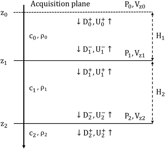
FIGURE 1. Wavefields in a 1D layered model.
DWI explicitly uses the time-space causality property of the wavefield in the inversion. Starting from the source-receiver layer near the surface, we recursively (not iteratively) build the model downward by fitting the earliest parts of the waveforms of pairs of source-receivers of short (or zero) offsets. We then extrapolate the sources and receivers downward to the bottom of the inverted region, and repeat the process.
To illustrate the DWI process, we assume that both the pressure waveform, P, and particle velocity,
where
DWI consists of four steps:
• Step 1. At the acquisition plane depth
• Step 2. We then extrapolate fields
This wavefield extrapolation can be done by many different methods. In 1d, we choose the phase shift approach shown here because it is easy to implement.
• Step 3. After extrapolation, the first impulse in
To determine the velocity,
• Step 4. Finally, we can use
The aforementioned process, using the recorded fields,
Simultaneous DWI for Both Velocity and Density
In the previous 1D DWI scheme, we assume the density is constant throughout the model. For the 1D inversion on models of depth dependent density profiles, there were some relevant work by Coen in 1980s (Coen, 1981a; Coen, 1981b; Coen, 1981c). In Coen’s work, the density and velocity are inverted separately using a dataset from oblique incident plane waves based on the Gel’fand-Levitan-Marchenko (GLM) theory (Agranovich and Marchenko, 1963; Berryman and Greene, 1980). In our study, instead of applying the GLM theory, we directly use the incident angle (
Assuming the wave is incident from medium-1 (
If we have two plane waves of two different incident angles
To increase robustness of the inversion, we can make use of waves of multiple incident angles (
In Eq. 7, for a plane wave at the incident angle
Assuming the incident wave angle is
In Step 1, Eq. 2, the relationship between the pressure and vertical component of the particle velocity, should be changed to
In Step 2, the extrapolation of up-going and down-going pressure fields should be modified as
In Step 3, using the amplitude ratio
In Step 4, we need to use Eqs 1, 8 to compose P and
Numerical Examples
In this section, we will present two synthetic examples to demonstrate the effectiveness of our proposed method: a simple layered model with six layers, and a more complex layered model with thirty-one layers. Both models are horizontally stratified. Within each layer, the velocity and density are constant. However, different layers have different properties. Both the top and bottom boundaries of the model are set up as half-space boundary conditions.
The synthetic data (pressure and particle velocity) in both examples are generated by a propagator matrix method (e.g., Eftekhar et al., 2018). The plane wave is injected at a depth of 0 m and propagated downward into the model. The receivers are placed at the same depth. Both the pressure and particle velocity wavefields are recorded at a time sampling interval of 1 ms.
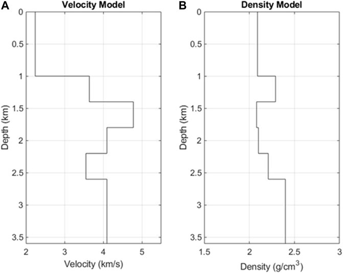
Example 1 In the first example, there are six layers (Figure 2) and the velocity contrast is up to 200%. Here we use a 15 Hz Ricker wavelet as the incident plane wave for the model (Figure 2). We conduct the modeling for four plane wave sources at different incident angles: 0, 5, 10, and 15°. The waveform records of the pressure and the vertical component of particle velocity are shown in Figure 3. In Figure 3, the recorded waveforms contain full information of the wavefields, including the primary reflections and multiples.Using the recorded data shown in Figure 3 and following the DWI steps in the previous section, we inverted for both the velocity and density profiles, shown in Figure 4. We also calculated the misfits in velocities and densities between the DWI results and the true models shown in Table 1, where most of them are less than 1%, except the velocity in the last layer (layer 6).To check the validity of the inverted model in the data space, we conduct a forward synthetic modeling using the DWI inverted model (Figure 4). The modeled waveforms fit the data very well (Figure 5). Both the primary reflections and the internal multiples can be reproduced by the DWI inverted model.
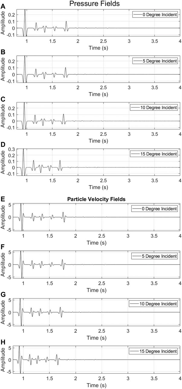
FIGURE 3. Recorded waveforms of pressure (A–D) and vertical component of particle velocity (E–H) in response to four different plane waves.
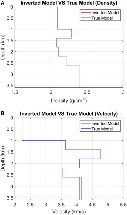
FIGURE 4. Comparisons between DWI inversion result and true model for both velocity (A) and density (B) structure.

TABLE 1. The misfit of velocities and densities between the inverted model and true model (the velocity and density information of the first layer are known).
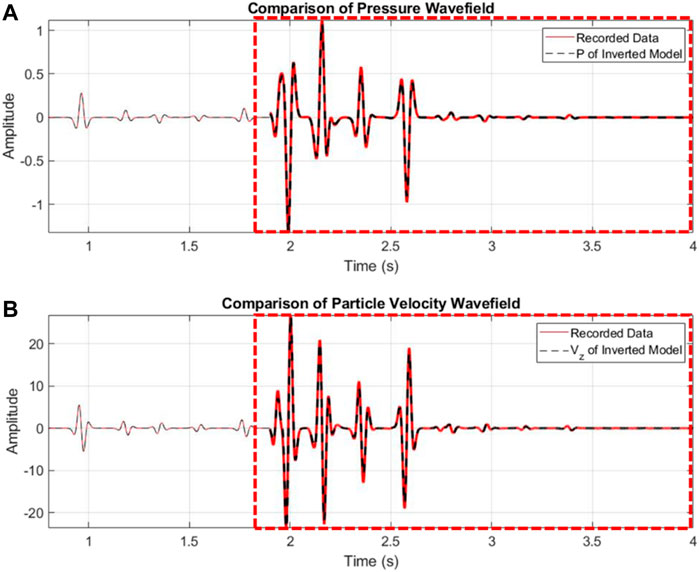
FIGURE 5. Comparisons of the recorded data (red) and synthetics (black) modeled using the DWI inverted model. (A) pressure waveforms; (B) particle velocity waveforms at the 0-degree incidence. Note the waveform amplitudes of the multiples in the red dashed box are amplified by 300 times.
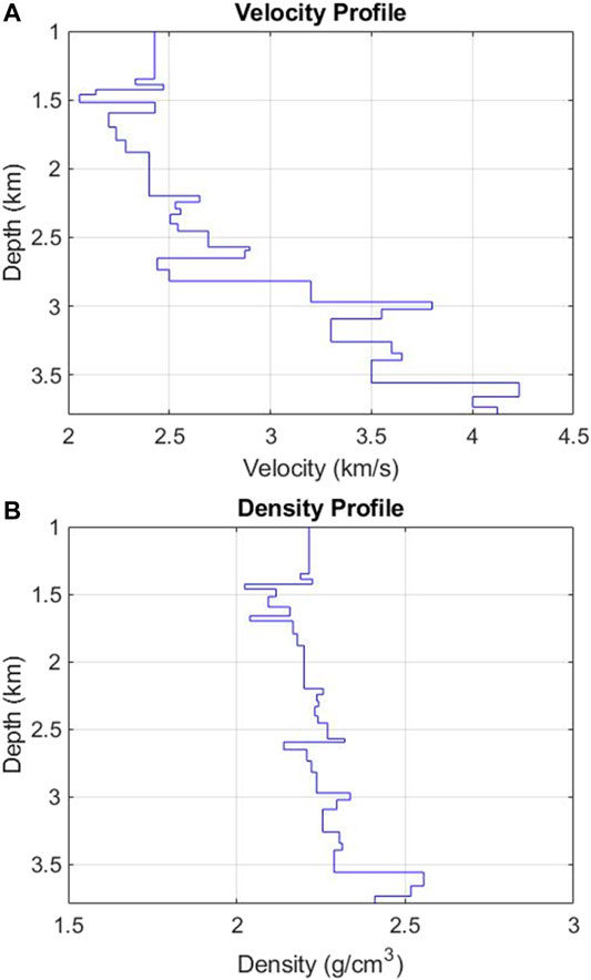
Example 2 In the second example, we build a model with 31 velocity and density layers (Figure 6). An 80 Hz Ricker wavelet was used as the incident plane wave source wavelet and we modeled the data for four plane waves at angles: 0, 5, 9, and 16°. The recorded waveform data of the pressure and the vertical particle velocity are shown in Figure 7.Compared with the recorded waveforms in the first example (Figure 3), both the primary reflections and the internal multiples (Figure 7) are much more complicated. Using these recorded data, we applied our DWI scheme and obtained the inversion results of velocity, density, and impedance models shown in Figure 8.From Figure 8 we can see that the DWI scheme almost exactly recovers the impedance model. For the velocity and density models, although there are some small misfits (less than 2%), the inverted models still agree well with the true model. To further examine the influences of these modeled misfits, here we also conduct a forward synthetic modeling based on the inverted model (Figure 8). The results are shown in Figure 9. The modeled waveforms using the DWI model fit the data very well including not only the primary reflections but also the internal multiples.
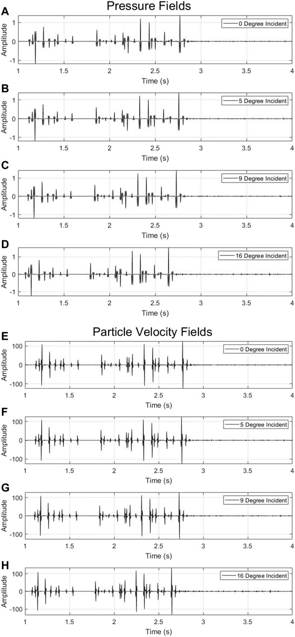
FIGURE 7. Recorded waveforms of pressure (A–D) and vertical component of particle velocity (E–H) in response to four different plane waves.
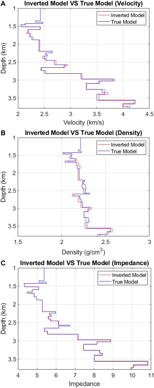
FIGURE 8. Comparisons between DWI inversion result and true model on velocity (A), density (B), and impedance (C) models.
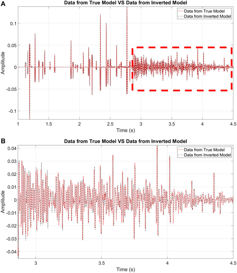
FIGURE 9. Comparisons of data (red) and synthetics (black) modeled using the DWI inverted model for pressure at the 0-degree incidence (A), the events in the red dashed box are amplified by 10 times. A zoom-in view of the events in the red dashed box in (A) is shown in (B).
Discussion
We remark on limitations of DWI. DWI depends on reflection events in data to invert for the subsurface model. If the true model is smooth and does not have many reflectors, DWI may fail to find the true model. If the incident angle is too large and the total reflection occurs, DWI is not able to invert for model parameters below the total reflection depth.
The performance of the recursive DWI scheme may suffer from the accumulation of errors as the inversion process goes from shallow to deep depths. Data redundancy can help. In order to resolve reflectivities into P-wave velocity contrast and density contrast, respectively, we need to use several distinct incident angles. If the range of incident angles is narrow, DWI may not be able to resolve Vp and density correctly.
It is also worthwhile to provide some general remarks on the differences between DWI and FWI. Based on the single-scattering approximation (Tarantola, 2005), FWI linearizes the global non-linear seismic inversion problem by iteratively minimizing the misfit between the recorded data and the model predicted data. For FWI, if the intial model is far from the true model, the FWI convergence can be a problem (Sirgue and Pratt, 2004). Different from FWI, DWI does not rely on an initial global model to start the waveform inversion process. It only needs the local velocity around the surface receivers. The DWI scheme converts the FWI global optimization problem into many localized reflectivity inversions by explicitly invoking the causality principle. Hence it reduces the nonlinearity significantly which is a strength over the FWI method. Another advantage for DWI is that it does not need low-frequency data as seen in our example 2. On the other hand, if the true model is smooth and data have only a few reflection events, FWI may perform better. In cases where DWI can be applicable, DWI can be significantly faster numerically to obtain a model.
There are also marked differences between DWI and the 1D inversion using the GLM theory. Most developments of the GLM theory are aiming at imaging and redatuming methods (e.g., Broggini et al., 2014; Wapenaar et al., 2014; van der Neut et al., 2015; Nowack and Kiraz, 2018). Recently, Wu and He (2020) used the GLM theory to invert for 1D impedance profile. For 1D GLM problem, a time to depth conversion is needed and is usually carried out by the Liouville transform. But for 2D and 3D spatial problems, a macro-velocity model need to be used and should be obtained a prior. However, for DWI, the inversion is localized in a shallow to deep fashion and the inverted model is automatically obtained in the depth domain and there is no need to use a global velocity model. In future we will show 2D inversion results in which the wavefield extrapolation is much more involved using integral equations.
Conclusion
We extend the scalar DWI scheme to invert for the subsurface density and velocity simultaneously, using multiple plane waves. Using recorded seismic data on the surface, our method inverts for the model parameters locally by explicitly employing time-space causality principle of the wavefield and recursively from shallow to deep depths. The new DWI scheme makes use of the angle dependent property of the reflectivity to solve for density and velocity simultaneously. The input seismic data to DWI must include all types of data including multiples. Numerical examples demonstrate the feasibility of the DWI approach to invert for both velocity and density using four plane wave sources. We find that the acoustic impedance profile is better resolved than the P-wave velocity or density owing to slight tradeoff (<1%) between the two parameters.
Data Availability Statement
The raw data supporting the conclusion of this article will be made available by the authors, without undue reservation.
Author Contributions
YZ, H-WZ, and ZL contributed to idea and design of the study. ZL realized the idea and generated numerical examples for testing. ZL wrote the first draft of the manuscript. All authors contributed to manuscript revision, read, and approved the submitted version.
Conflict of Interest
The authors declare that the research was conducted in the absence of any commercial or financial relationships that could be construed as a potential conflict of interest.
Publisher’s Note
All claims expressed in this article are solely those of the authors and do not necessarily represent those of their affiliated organizations, or those of the publisher, the editors and the reviewers. Any product that may be evaluated in this article, or claim that may be made by its manufacturer, is not guaranteed or endorsed by the publisher.
References
Alkhalifah, T., and Plessix, R.-É. (2014). A Recipe for Practical Full-Waveform Inversion in Anisotropic media: An Analytical Parameter Resolution Study. Geophysics 79 (3), R91–R101. doi:10.1190/geo2013-0366.1
Berryman, J. G., and Greene, R. R. (1980). Discrete Inverse Methods for Elastic Waves in Layered media. Geophysics 45 (2), 213–233. doi:10.1190/1.1441078
Bourgeois, A., Jiang, B. F., and Lailly, P. (1989). Linearized Inversion: a Significant Step beyond Pre-stack Migration. Geophys. J. Int. 99 (2), 435–445. doi:10.1111/j.1365-246x.1989.tb01700.x
Broggini, F., Snieder, R., and Wapenaar, K. (2014). Data-driven Wavefield Focusing and Imaging with Multidimensional Deconvolution: Numerical Examples for Reflection Data with Internal Multiples. Geophysics 79 (3), WA107–WA115. doi:10.1190/geo2013-0307.1
Brossier, R., Operto, S., and Virieux, J. (2009). Seismic Imaging of Complex Onshore Structures by 2D Elastic Frequency-Domain Full-Waveform Inversion. Geophysics 74 (6), WCC105–WCC118. doi:10.1190/1.3215771
Chen, G.-X., Wu, R.-S., and Chen, S.-C. (2018). Reflection Multi-Scale Envelope Inversion. Geophys. Prospecting 66 (7), 1258–1271. doi:10.1111/1365-2478.12624
Coen, S. (1981a). Density and Compressibility Profiles of a Layered Acoustic Medium from Precritical Incidence Data. Geophysics 46 (9), 1244–1246. doi:10.1190/1.1441262
Coen, S. (1981c). On the Elastic Profiles of a Layered Medium from Reflection Data. Part II: Impulsive point Source. The J. Acoust. Soc. America 70 (5), 1473–1479. doi:10.1121/1.387104
Coen, S. (1981b). On the Elastic Profiles of a Layered Medium from Reflection Data. Part I. Plane‐wave Sources. J. Acoust. Soc. America 70 (1), 172–175. doi:10.1121/1.386669
Eftekhar, R., Hu, H., and Zheng, Y. (2018). Convergence Acceleration in Scattering Series and Seismic Waveform Inversion Using Nonlinear Shanks Transformation. Geophys. J. Int. 214 (3), 1732–1743. doi:10.1093/gji/ggy228
Gauthier, O., Virieux, J., and Tarantola, A. (1986). Two‐dimensional Nonlinear Inversion of Seismic Waveforms: Numerical Results. Geophysics 51 (7), 1387–1403. doi:10.1190/1.1442188
Goupillaud, P. L. (1961). An Approach to Inverse Filtering of Near‐surface Layer Effects from Seismic Records. Geophysics 26 (6), 754–760. doi:10.1190/1.1438951
Jeong, W., Lee, H.-Y., and Min, D.-J. (2012). Full Waveform Inversion Strategy for Density in the Frequency Domain. Geophys. J. Int. 188 (3), 1221–1242. doi:10.1111/j.1365-246x.2011.05314.x
Kim, Y., Shin, C., Calandra, H., and Min, D.-J. (2013). An Algorithm for 3D Acoustic Time-Laplace-Fourier-Domain Hybrid Full Waveform Inversion. Geophysics 78 (4), R151–R166. doi:10.1190/geo2012-0155.1
Lailly, P. (1983). “The Seismic Inverse Problem as a Sequence of Before-Stack Migrations,” in Conference on Inverse Scattering: Theory and Applications (Philadelphia, PA: SIAM), 206–220.
Liu, Y., He, B., Lu, H., Zhang, Z., Xie, X., and Zheng, Y. (2018). Full Intensity Waveform Inversion. Geophysics 86 (6), R649–R658.
Liu, Y., He, B., Zhang, Z., Zheng, Y., and Li, P. (2020). Reflection Intensity Waveform Inversion. Geophysics. doi:10.1190/geo2019-0590.1191
Liu, Z., and Zheng, Y. (2017). “Applications of the Direct-Waveform Inversion on 2D Models,” in 87th Annual International Meeting, SEG, Expanded Abstracts (Houston, TX: Series editor Society of Exploration Geophysicists), 1687–1691. doi:10.1190/segam2017-17791763.1
Liu, Z., and Zheng, Y. (2015). “Direct Waveform Inversion,” in 85th Annual International Meeting, SEG, Expanded Abstracts (New Orleans, LA: Series editor Society of Exploration Geophysicists), 1268–1273. doi:10.1190/segam2015-5923910.1
Luo, J., and Wu, R.-S. (2015). Seismic Envelope Inversion: Reduction of Local Minima and Noise Resistance. Geophys. Prospecting 63 (3), 597–614. doi:10.1111/1365-2478.12208
Mora, P. (1987). Nonlinear Two‐dimensional Elastic Inversion of Multioffset Seismic Data. Geophysics 52 (9), 1211–1228. doi:10.1190/1.1442384
Nowack, R. L., and Kiraz, M. S. R. (2018). Virtual Green's Functions Using Seismic Interferometry and Marchenko Redatuming. Seismological Res. Lett. 89 (2A), 613–619. doi:10.1785/0220170211
Sears, T. J., Singh, S. C., and Barton, P. J. (2008). Elastic Full Waveform Inversion of Multi-Component OBC Seismic Data. Geophys. Prospecting 56 (6), 843–862. doi:10.1111/j.1365-2478.2008.00692.x
Shin, C., and Cha, Y. H. (2008). Waveform Inversion in the Laplace Domain. Geophys. J. Int. 173 (3), 922–931. doi:10.1111/j.1365-246x.2008.03768.x
Shin, C., and Ha, W. (2008). A Comparison between the Behavior of Objective Functions for Waveform Inversion in the Frequency and Laplace Domains. Geophysics 73 (5), VE119–VE133. doi:10.1190/1.2953978
Sirgue, L., and Pratt, R. G. (2004). Efficient Waveform Inversion and Imaging: A Strategy for Selecting Temporal Frequencies. Geophysics 69 (1), 231–248. doi:10.1190/1.1649391
Tarantola, A. (1986). A Strategy for Nonlinear Elastic Inversion of Seismic Reflection Data. Geophysics 51 (10), 1893–1903. doi:10.1190/1.1442046
Tarantola, A. (2005). Inverse Problem Theory and Methods for Model Parameter Estimation. Philadelphia, PA: SIAM.
Tarantola, A. (1984). Inversion of Seismic Reflection Data in the Acoustic Approximation. Geophysics 49 (8), 1259–1266. doi:10.1190/1.1441754
van der Neut, J., Wapenaar, K., Thorbecke, J., and Slob, E. (2015). Practical Challenges in Adaptive Marchenko Imaging. 77th EAGE Conf. Exhibition 2015 2015, 1–5. doi:10.1190/segam2015-5791035.1
Virieux, J., and Operto, S. (2009). An Overview of Full-Waveform Inversion in Exploration Geophysics. Geophysics 74 (6), WCC1–WCC26. doi:10.1190/1.3238367
Wapenaar, K., Thorbecke, J., Van Der Neut, J., Broggini, F., Slob, E., and Snieder, R. (2014). Marchenko Imaging. Geophysics 79 (3), WA39–WA57. doi:10.1190/geo2013-0302.1
Warner, M., Ratcliffe, A., Nangoo, T., Morgan, J., Umpleby, A., Shah, N., et al. (2013). Anisotropic 3D Full-Waveform Inversion. Geophysics 78 (2), R59–R80. doi:10.1190/geo2012-0338.1
Wu, R.-S., Luo, J., and Wu, B. (2014). Seismic Envelope Inversion and Modulation Signal Model. Geophysics 79 (3), WA13–WA24. doi:10.1190/geo2013-0294.1
Wu, R.-S., and Zheng, Y. (2014). Non-linear Partial Derivative and its De Wolf Approximation for Non-linear Seismic Inversion. Geophys. J. Int. 196 (3), 1827–1843. doi:10.1093/gji/ggt496
Wu, R., and He, H. (2020). “Inverse Scattering for Schrödinger Impedance Equation and Simultaneous ρ-v Inversion in Layered Media,” in 82nd EAGE Annual Conference & Exhibition, 2020, 1–5
Keywords: full waveform inversion (FWI), velocity model building, density inversion, waveform inversion, multi-parameter inversion, modeling
Citation: Liu Z, Zheng Y and Zhou H-W (2022) Simultaneous Inversion of Layered Velocity and Density Profiles Using Direct Waveform Inversion (DWI): 1D Case. Front. Earth Sci. 9:800312. doi: 10.3389/feart.2021.800312
Received: 22 October 2021; Accepted: 03 December 2021;
Published: 10 January 2022.
Edited by:
Christine Thomas, University of Münster, GermanyReviewed by:
Jie Zhang, University of Science and Technology of China, ChinaYa-juan Xue, Chengdu University of Information Technology, China
Copyright © 2022 Liu, Zheng and Zhou. This is an open-access article distributed under the terms of the Creative Commons Attribution License (CC BY). The use, distribution or reproduction in other forums is permitted, provided the original author(s) and the copyright owner(s) are credited and that the original publication in this journal is cited, in accordance with accepted academic practice. No use, distribution or reproduction is permitted which does not comply with these terms.
*Correspondence: Zhonghan Liu, lyuuu@hotmail.com
 Zhonghan Liu
 Yingcai Zheng
 Hua-Wei Zhou