Comparative Study on Concrete Crack Detection of Tunnel Based on Different Deep Learning Algorithms
 Hongliang Yu1
  Dongbiao Li
- 1CCCC Nanjing Traffic Engineering Management Co., Ltd., Nanjing, China
- 2College of Science, Hohai University, Nanjing, China
- 3College of Civil and Transportation Engineering, Hohai University, Nanjing, China
The computer vision inspection of surface cracks in concrete structures has the characteristics of convenient and efficient 24-h on-site inspection. In this paper, the instance segmentation method and semantic segmentation method are used to realize the surface crack recognition of concrete structures, and a concrete crack detection method based on two different deep learning methods is designed. Experiments show that in scenarios where detection accuracy is required, compared with the Mask Region with Convolutional Neural Network method, the U-Net model improves the model segmentation accuracy through up-sampling and skip connection, and its Recall, Kappa, and Dice are increased by 6.88, 1.94, and 7.72%, respectively. In the scene of positioning requirements, Mask Region with Convolutional Neural Network has a better detection effect than U-Net for very thin and inconspicuous cracks, effectively avoiding the situation of missing cracks.
Introduction
The development of economic strength is inseparable from large-scale infrastructure construction. While expanding infrastructure construction, it is also necessary to detect and maintain the existing infrastructure. The security of the infrastructure is closely related to the safety of human life and property.
Concrete has become the most common material used in infrastructure construction because of its strong, durable, water-resistant, and heat-resistant properties (Dong, 2013). However, with the influence of the external environment and artificial factors, concrete engineering structures, such as tunnels, bridges, buildings, and highways, are gradually aging and easy to produce structural damage (Sun et al., 2012). Moreover, the structural damage may result in uneven force, weak carrying capacity, and even lead to collapse, fracture, and other serious safety accidents (Xu, 2007). To extend the service life of concrete engineering structures, it is essential to carry out regular inspections and take pertinent measures to prevent the occurrence of safety accidents (Wang, 2004; Yi, 2006; Weng, 2019). Crack is one of the main diseases of concrete engineering structures. An excessive crack will reduce the bearing capacity, waterproof performance, and durability of concrete engineering structures. If the cracks of concrete structures are not treated in time, it may cause severe safety accidents. Therefore, crack detection is an important work of engineering quality assessment (Jiang et al., 2010).
In traditional crack detection, artificial vision is often adopted to detect cracks. This method is not only inefficient but also has low detection accuracy (Xu et al., 2020). Digital image processing methods mainly include threshold segmentation (Han and Wang, 2002), edge detection (Davis, 1975), spectral analysis (Adhikari et al., 2014), etc. These methods can effectively detect cracks for images with single background, less noise, and obvious crack characteristics. The pixels in the crack area are low, and the overall appearance color characteristics are gray. It is easy to be affected by noise such as dead leaves, shadows, and scratches of pixels in the actual environment, resulting in false detection. Therefore, the crack detection method based on digital image processing has large error and low generalization ability. With the rapid development of deep learning, more and more researchers apply deep learning models to the detection and recognition of cracks in concrete. Kim and Cho (2018) used the AlexNet network to train the collected crack images and obtained better classification accuracy. Zhang et al. (2016) introduced a crack detection method based on sliding windows, but the speed is slow. Ren et al. (2015) proposed the Faster Region with Convolutional Neural Network (Faster RCNN) algorithm, which improved the accuracy of the object detection task. Liu et al. (2016) proposed Single Shot MultiBox Detector to further improve the detection speed. Wang et al. (2018) pointed out that the Faster RCNN algorithm is more effective in detecting cracks. Li and Xiong (2021) applied the Single Shot MultiBox Detector algorithm to crack detection. Meng et al. (2021) demonstrated a concrete crack recognition model based on a convolutional neural network. Based on a convolutional neural network algorithm, Gao et al. (2020) described a concrete bridge crack identification and location technology. The methods mentioned earlier do not consider the characteristics of long and continuous cracks, but only the border will be roughly framed out of the crack area.
In this paper, concrete crack detection based on the two methods of Region with Convolutional Neural Network (Mask RCNN) (He et al., 2017) and U-Net (Ronneberger et al., 2015) is proposed. Compared with the target detection method, both methods can divide the crack area, output the crack mask, and maintain the morphology information of the crack, and the detection results are more precise than the detection frame. Based on these two methods, the advantages and disadvantages of each method are compared and analyzed from multiple perspectives.
Crack Detection Algorithm
In the research task of deep learning concrete crack detection, this paper mainly uses Mask RCNN and U-Net models to analyze and compare the experimental results and uses Accuracy, Recall, Kappa, and Dice for comprehensive evaluation. The flowchart is shown in Figure 1.
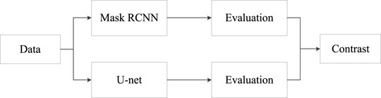
FIGURE 1. Flow chart of research study.
Mask Region With Convolutional Neural Network Algorithm Framework
Based on Faster RCNN (Zhang and Guo, 2021), He further proposed the instance segmentation network Mask RCNN. Mask RCNN can efficiently complete the target detection and predict the mask of the input object (Li et al., 2020). Mask RCNN is based on Faster RCNN and joins the fully connected partition network after the basic feature network. Mask RCNN changes from two tasks (classification + regression) to three tasks (classification + regression + segmentation) (Ying, 2020). The same two stages as Faster RCNN are adopted by Mask RCNN.
The same first level [Regional Proposal Network (RPN)] is applied in Phase I: Scanning images and generating area proposals (an area that may contain a target) (Song et al., 2021). Phase II, in addition to prediction types and bbox regression, a branch of the full convolution network is added. This branch predicts the corresponding binary mask for each ROI to indicate whether a given pixel is part of the target. The advantage of this method is that the whole task can be simplified into a multistage pipeline, decoupling the relationship between multiple subtasks.
The network structure framework diagram based on Mask RCNN crack detection is shown in Figure 2.
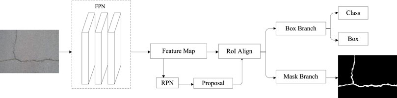
FIGURE 2. Mask RCNN.
Mask RCNN is a two-stage target detection method. The first stage generates a series of recommendation boxes through the RPN. The second stage obtains the feature matrix of the target on the feature map by aligning the proposed box generated by the first stage with the area of interest and finally predicts the three branches of the classification, boundary box regression, and mask (Wang et al., 2021). The three branches are performed simultaneously. Mask RCNN's loss consists of three parts, as shown in Eq. 1.
In the formula,
The cross-entropy loss function is adopted for classification loss, as shown in Eq. 2.
In the formula,
The SmoothL1 loss function is adopted for the bounding box regression loss, as shown in Eq. 3.
In the formula,
The mask loss function is calculated using the mask generated by the mask branch prediction, for
In the formula,
U-Net Algorithm Framework
U-Net's network structure is entirely composed of the convolutional layer. U-Net's network structure got its name because the network structure resembles the English letter “U.” The concrete crack detection network structure based on the U-Net network is shown in Figure 3.

FIGURE 3. U-Net network.
U-Net is a variant of a full convolution neural network that is mainly encoder–decoder structure. An encoder is mainly used to extract image features, and a decoder is mainly used to decode the feature information extracted by an encoder. U-Net network was originally designed to solve the segmentation task at the cell level. Because of the good effect, it can be applied to other semantic segmentation tasks, such as satellite image segmentation and industrial defect detection. Pixel-level image segmentation can be realized by the U-Net network method. The fusion of shallow features and deep features is efficiently used to retain many details of the original image to the greatest extent (Jin et al., 2021).
The encoder consists of four down-sampling modules, which are composed of two 3*3 convolution layers and a pooling layer. The convolution layer is mainly used to extract feature information and change the number of channels in the feature graph. The pooling layer adopts maximum pooling to reduce the dimension of the feature graph. Different feature maps focus on different information, whereas shallow convolution focuses on texture features, whereas feature maps of deep network layers have large receptive fields, and convolution focuses on the essential features of images (Zhu et al., 2019; Zhu et al., 2021).
The decoder is composed of four up-sampling modules, which are composed of a deconvolution layer and two 3*3 convolution layers. The deconvolution layer is mainly used to restore the original resolution of the image and then fuse different feature images by channel splicing. Some edge features are lost in down-sampling feature extraction, and the lost features cannot be retrieved from up-sampling. Therefore, image edge features are recovered by feature graph Mosaic.
In the training process, the cross-entropy loss function fused with the sigmoid function was adopted, and finally, the mean value of all pixel loss was calculated, which was consistent with the Mask RCNN mask loss function, as shown in Eq. 5
In the formula,
U-Net is one of the earliest algorithms for semantic segmentation using multi-scale features, and its U-shaped structure also inspired many later algorithms. U-Net also has several disadvantages:
1) Effective convolution increases the difficulty and universality of model design. Many algorithms directly use the same convolution. The same convolution can also avoid the edge cutting operation before feature map merging.
2) The edge cutting form and feature map are not symmetrical.
Evaluation Indicator
Crack detection is an image semantic segmentation task, and each pixel is classified into two categories. Therefore, this paper uses Accuracy, Recall, Kappa coefficient, and Dice as the result evaluation. The evaluation index formula is as follows:
In the formula, A is GT, that is, the manually marked area, and B is the area obtained by model segmentation. The Dice range is between [0,1]. The larger the value, the higher the overlap, that is, the closer to the artificially fine-labeled GT.
Experimental Results and Analysis
The hardware environment of this experiment is GPU NVIDIA GeForce RTX 2080, Windows 10 operating system, 32-GB memory, and 8-GB video memory. The software environments are Python 3.7.3, TensorFlow 1.14.0, and Pytorch 1.6.0. The crack detection model based on Mask RCNN is tested in the TensorFlow framework. The crack detection model based on U-Net is tested in the Pytorch framework.
Experimental Data
In this paper, experiments are carried out on the open fracture dataset CFD (Shi et al., 2016). The image size is 480 × 320. Some samples are shown in Figure 4 One hundred fracture images were selected from the CFD dataset, 80 images were selected as the training set, and 20 images were selected as the validation set. Open source is adopted to mark tool Labelme to mark the crack edge to form a closed loop, as shown in Figure 5. The red line in the figure represents the connecting line of the mark point on the edge of the crack. Then, the JSON file containing GT (Ground Truth) information was exported. The training data of Mask RCNN need to be inputted into the network in the form of a JSON file corresponding to each image. U-Net requires that each image corresponds to a mask image (GT, which can be generated by JSON conversion, as shown in Figure 6) input into the network for training.
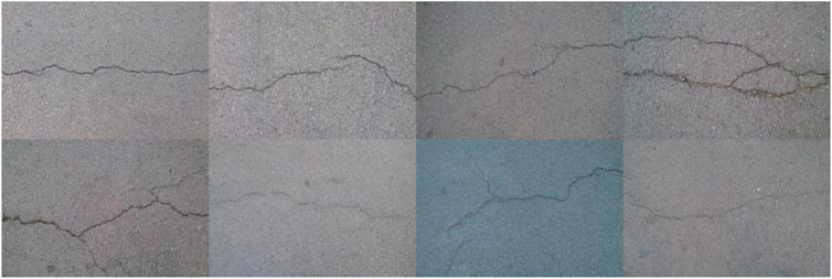
FIGURE 4. CFD sample.
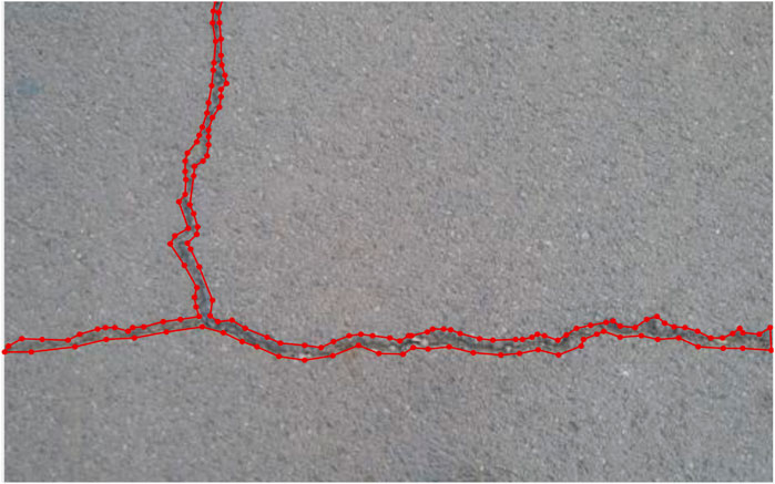
FIGURE 5. Mark image.
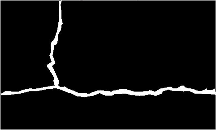
FIGURE 6. Ground Truth.
Experimental Results
Qualitative Analysis
To ensure that the comparison between Mask RCNN and U-Net model is relatively fair, the following experimental results are obtained under the same parameter settings: batch size is set to 2, the maximum number of training rounds is set to 20 epoch, and the learning rate is set to 0.0001. Some test results are shown in Figures 7A–D.
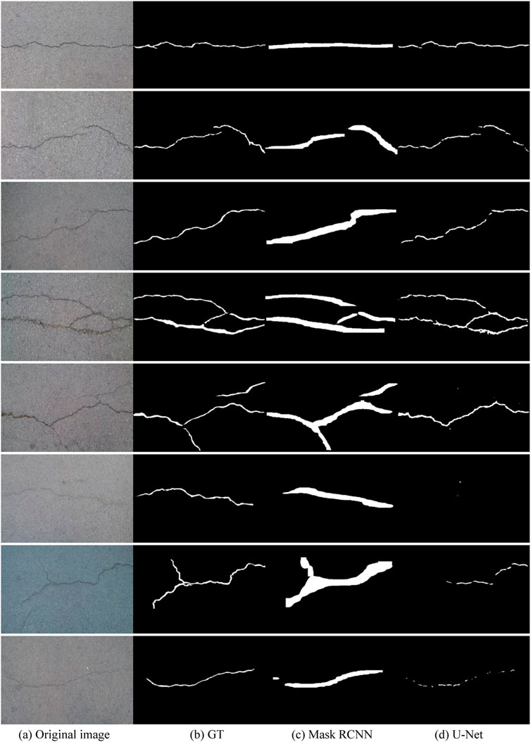
FIGURE 7. Result constrast. (A) Original image. (B) GT. (C) Mask RCNN. (D) U-Net.
From the qualitative results in Figure 6, we can see that cracks are split more finely by U-Net. Mask RCNN can get a relatively rough result. From top to bottom, in the first to fourth rows, comparing the third and fourth columns, both Mask RCNN and U-Net can cover the true crack position. U-Net can get the segmentation result close to GT. From this point of view, precise crack detection is an advantage of U-Net. From the top–down, the fifth to the eighth rows, compared with the third and fourth columns, the split result of Mask RCNN can still cover most of the crack areas in the original map. Some crack areas in U-Net have not been detected successfully, resulting in leakage or partial leakage, especially in the sixth row. The Mask RCNN result can roughly cover the cracks, whereas only two small points are detected in the U-Net result, and the cracks cannot be detected. In view of the analysis discussed earlier, the crack area is accurately segmented by U-Net under the premise that the crack characteristics of the original image are obvious. When the crack characteristics of Mask RCNN are not obvious enough, the segmentation results obtained are not precise enough, but the cracks are still mostly covered. The reason for the results mentioned earlier may be that U-Net lost some information of pixels in the process of down-sampling and resampling the original image.
Quantitative Analysis
For the Mask RCNN and U-Net models, 80 training samples and 20 validation samples were evaluated and analyzed for Accuracy, Recall, Kappa, and Dice, as shown in Table 1.
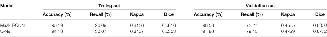
TABLE 1. Comparison of evaluation indicators.
The U-Net method has an average accuracy of 97.86% for crack segmentation pixels in the verification set, a recall rate of 79.15%, a kappa coefficient of 0.4729, and a Dice value of 0.6772. The Mask RCNN method has an average accuracy rate of 98.56% on the verification set, a recall rate of 72.27%, a kappa coefficient of 0.4535, and a Dice value of 0.6000. However, the Accuracy of the U-Net model is lower than that of the Mask RCNN model because the indicator is a comprehensive calculation of positive and negative samples. In the image, the area of the image where the crack area (positive sample) is located is small, while in the background area (negative sample). The proportion of the area occupied in the image is larger, which more reflects the information of the negative sample. According to the evaluation index Recall, the analysis of the proportion of the real area occupied by the fracture area predicted by the model, the Recall of the U-Net model is better than the Mask RCNN. Because the crack area in the image occupies a small proportion relative to the background area, resulting in the imbalance of positive and negative samples, Accuracy and Recall cannot fully effectively evaluate the comparative effect of the model. This paper uses the comprehensive evaluation index coefficients Kappa and Dice for analysis. The Kappa and Dice index values of the U-net model are higher than those of the Mask RCNN model, indicating that the U-Net model has a better effect in the task of crack segmentation.
For the two models, the average time required to predict an image and how many images (frame per second) can be detected in 1 s are calculated, as shown in Table 2.
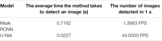
TABLE 2. Comparison of detection time.
It can be seen from Table 2 that the average time for U-Net to detect an image is only 0.0227 s, which is much shorter than Mask RCNN's 0.7162 s. U-Net can detect 44 images per second on average, whereas Mask RCNN can only detect 1.4 images per second. Because Mask RCNN is a two-stage anchor-based model, the model first performs RPN screening on the anchor and recommends the proposals, and then scales the ROI to predict the offset and the predicted probability. Relatively speaking, the U-Net structure is more simplified, through up-sampling and skip connection carrying out feature map splicing to predict each pixel, with fewer training parameters; only the input image passes through the encoder and the decoder to directly obtain the segmentation mask, and the detection speed is faster.
This paper mainly compares the effects of the two models on the task of crack segmentation, and the corresponding model can be selected according to the actual task situation. For model detection accuracy, comprehensive evaluation indicators and detection speed, the U-Net model has a better fitting effect. For crack warning, combined with the mask map in Figure 6, the U-Net model undergoes up-sampling and pooling operations, resulting in the loss of the spatial relationship between the target pixel and surrounding pixels. The crack mask predicted by the U-Net model is relatively discrete. U-Net mask image may have certain missing errors. The Mask RCNN model predicts more redundantly, but all cover the crack area, and the visual effect is clearer. Therefore, according to different tasks, the U-Net model and the Mask RCNN model have different functions.
Conclusion
The research of crack detection based on deep learning proposed in this paper uses the Mask RCNN model and U-Net model for experiments. According to different purposes, this paper recommends different models. Under the requirements of real-time segmentation and high precision, the U-Net model has the best comprehensive evaluation index compared with the Mask RCNN model. Therefore, this paper recommends using the U-Net model for crack detection. The U-Net model mainly extracts image feature information through down-sampling, maps the feature information to high-dimensional, uses skip-connection to splice and fuse the up-sampled information, and maps to low-dimensional through deconvolution, which significantly improves crack segmentation accuracy.
In scenes with low segmentation accuracy and time requirements, the detection results only need to roughly locate the cracks to meet the actual needs of quality assessment in concrete engineering. Compared with U-Net, Mask RCNN predicts the visual effect of the crack mask. Well, the crack mask area is relatively low and easy to locate, so this paper recommends using the Mask RCNN model. Mask RCNN adopts a two-stage idea, selects the suggestion proposals through RPN, and further performs crack detection and segmentation. It is better than U-Net for the detection of very fine cracks with inconspicuous characteristics, effectively avoiding the missed detection of large areas of cracks.
The disadvantage is that the two models still have certain flaws in crack detection. Therefore, future work will post-process the results of the two models. Both Mask RCNN and U-Net crack masks are processed by morphological methods to improve the mask prediction effect.
Data Availability Statement
The raw data supporting the conclusion of this article will be made available by the authors without undue reservation.
Author Contributions
All authors listed have made a substantial, direct, and intellectual contribution to the work and approved it for publication.
Funding
This work has been supported by the National Natural Science Foundation of China (Key Program, grant no. 41830110), China Communications Maintenance Group 2020 major scientific and technological research and development projects (27100020Y248, 27100020Y251, and 27100020Y249). The authors gratefully acknowledge these supports.
Conflict of Interest
Authors HY, LZ and DL are employed by CCCC Nanjing Traffic Engineering Management Co., Ltd.
The remaining authors declare that the research was conducted in the absence of any commercial or financial relationships that could be construed as a potential conflict of interest.
Publisher’s Note
All claims expressed in this article are solely those of the authors and do not necessarily represent those of their affiliated organizations, or those of the publisher, the editors and the reviewers. Any product that may be evaluated in this article, or claim that may be made by its manufacturer, is not guaranteed or endorsed by the publisher.
References
Adhikari, R. S., Moselhi, O., and Bagchi, A. (2014). Image-based Retrieval of concrete Crack Properties for Bridge Inspection. Automation in Construction 39 (4), 180–194. doi:10.1016/j.autcon.2013.06.011
Davis, L. S. (1975). A Survey of Edge Detection Techniques. Comp. Graphics Image Process. 4 (3), 248–270. doi:10.1016/0146-664x(75)90012-x
Gao, Q., Wang, Y., Liu, C., and Liu, B. (2020). Crack Identification and Location Technology of Concrete Bridge Based on Convolution Neural Network Algorithm[A]. High Way 65 (09), 268–274.
Han, S., and Wang, L. (2002). A Survey of Thresholding Methods for Image Segmentation[J]. Syst. Eng. Electron. Techn. 24 (6), 91–94. doi:10.3321/j.issn:1001-506X.2002.06.027
He, K., Gkioxari, G., Dollár, P., et al. (2017). “Mask r-Cnn[C],” in Proceedings of the IEEE International Conference on Computer Vision, New York, 2961–2969.
Jiang, X., Xiao, B., and Wang, Y. (2010). Crack Analysis and Prevention of GRF Cast in Place Concrete Hollow Slab[A]. Construction Technology[A], 1002–8498.
Jin, Z., Wu, B., and Qiu, C. (2021). “Sparse Seismic Trace Velocity Pickup Method Based on U-Net Convolutional Neural Network[C],” in Proceedings of 2021 geophysical technology seminar of China Petroleum Society, Chengdu, Sichuan, September 27, 2021.
Kim, B., and Cho, S. (2018). Automated Vision-Based Detection of Cracks on Concrete Surfaces Using a Deep Learning Technique. Sensors 18 (10), 3452–3453. doi:10.3390/s18103452
Li, H., Li, M., Li, K., and Zhao, X. (2020). Application of Mask RCNN Model in Pavement Defect Detection[A]. Scientific Technol. innovation 20, 2096–4390.
Li, X., and Xiong, J. (2021). Crack Recognition Based on Deep Learning SSD Target Detection Algorithm. J. Nanchang Univ. 43 (1), 43–51. doi:10.13764/j.cnki.ncdg.2021.01.007
Liu, W., Anguelov, D., Erhan, D., Szegedy, C., Reed, S., Fu, C.-Y., et al. (2016). SSD: Single Shot MultiBox Detector. Eur. Conf. Comp. Vis. (9905), 21–37. doi:10.1007/978-3-319-46448-0_2
Meng, Q., Wan, D., Wu, H., et al. (2021). Image Recognition Method of Concrete Cracks Based on Convolutional Neural Network[J]. J. Shenyang Jianzhu Univ., 05–832.
Ren, S., He, K., Girshick, R., and Sun, J. (2015). Faster R-CNN: Towards Real-Time Object Detection with Region Proposal Networks. IEEE Trans. Pattern Anal. Mach Intell. 39 (6), 1137–1149. doi:10.1109/TPAMI.2016.2577031
Ronneberger, O., Fischer, P., Brox, T., et al. (2015). “U-net: Convolutional Networks for Biomedical Image Segmentation[C],” in International Conference on Medical Image Computing and Computer-Assisted Intervention, Lima, Peru, 18 May, 234–241. doi:10.1007/978-3-319-24574-4_28
Shi, Y., Cui, L., Qi, Z., Meng, F., and Chen, Z. (2016). Automatic Road Crack Detection Using Random Structured Forests. IEEE Trans. Intell. Transport. Syst. 17 (12), 3434–3445. doi:10.1109/tits.2016.2552248
Song, Z., Zhang, J., Tan, X., Liu, B., Bu, X., et al. (2021). A Quantitative Method for Cornus Jaw Pigmentation in Cephalopods Based on Mask-RCNN Image Segmentation [A]. Shanghai: Fishery Modernization.
Sun, Z., Yang, H., Jiang, Z., et al. (2012). Causes and Preventive Measures of Cracks in Concrete Structure[J]. Concrete world, 44–50.
Wang, M., Li, D., Chen, L., et al. (2021). An Improved Mask RCNN Algorithm Based on Adaptive-Threshold Non-maximum Suppression[A]. Comp. Eng. Sci.
Wang, P. (2004). Prevention and Treatment of Common Concrete Cracks[A]. J. Anhui Electr. Eng. Prof. Tech. Coll., 1672–9706.
Wang, W., Wu, B., and Yang, S. (2018). “Road Damage Detection and Classification with Faster R-CNN[C],” in 2018 IEEE International Conference on Big Data (Big Data), Seattle, WA, USA, 10-13 Dec. 2018, 5220–5223.
Weng, P. (2019). Research on Segmentation Algorithm of Pavement Crack in Complex Environment[D]. Zhengzhou University.
Xu, G., Liao, C., Chen, J., et al. (2020). Extraction of Apparent Crack Information of Concrete Based on HU-Res Net[J]. Comp. Eng. 46 (11), 279–285.
Xu, H. (2007). Research on Concrete Crack Detection Technology Based on Optical Fiber Sensor Network[D]. Shijiazhuang, Hebei: Shijiazhuang Tiedao University.
Yi, L. (2006). Measuremen Tand Analysis of Crack Feature of Concrete Surface Based on Digital Image Processing Techniques[D]. Southeast University.
Ying, L (2020). The Research of Pavement Cracking Detection Technology Based on Mask R-CNN[D]. Xi’an, Shaanxi: Chang’an University.
Zhang, L., Yang, F., Zhang, Y., and Zhu, Y. (2016). “Road Crack Detection Using Deep Convolutional Neural Networks[C],” in 2016 IEEE International Conference on Image Processing (ICIP), Phoenix, AZ, USA, 25-28 Sept. 2016, 3708–3712.
Zhang, T., and Guo, Z. (2021). Research on Transmission Line Insulator Detection Based on Improved Faster RCNN[J]. Design Application 28 (10), 63–67+77.
Zhu, S., Du, J., Li, Y., et al. (2019). Method for Bridge Crack Detection Based on the U-Net Convolutional Networks[J]. Journal of Xidian University, 1001–2400.
Keywords: concrete crack detection, mask RCNN, u-net, deep learning, tunnel
Citation: Yu H, Zhu L, Li D, Wang Q, Liu X and Shen C (2022) Comparative Study on Concrete Crack Detection of Tunnel Based on Different Deep Learning Algorithms. Front. Earth Sci. 9:817785. doi: 10.3389/feart.2021.817785
Received: 18 November 2021; Accepted: 28 December 2021;
Published: 10 March 2022.
Edited by:
Chaojun Jia, Central South University, ChinaReviewed by:
Milad Janalipour, K. N. Toosi University of Technology, IranYuyuan Chen, Kyushu University, Japan
Yongshuai Wan, Zhengzhou University, China
Copyright © 2022 Yu, Zhu, Li, Wang, Liu and Shen. This is an open-access article distributed under the terms of the Creative Commons Attribution License (CC BY). The use, distribution or reproduction in other forums is permitted, provided the original author(s) and the copyright owner(s) are credited and that the original publication in this journal is cited, in accordance with accepted academic practice. No use, distribution or reproduction is permitted which does not comply with these terms.
*Correspondence: Dongbiao Li, 942706856@qq.com