Brief analysis of the development characteristics and deformation mechanism of ground fissures on the MH Highway in the Ethiopian Rift Valley
 Weimin Liu
 Cheng Xu2
 - 1CCCC First Highway Consultants Co., Ltd., Xi’an, China
- 2Xi’an China Highway Geotechnical Engineering Co., Ltd., Xi’an, China
Ground fissures are widely developed in the Ethiopian Rift Valley, posing a major threat to the construction of the proposed Modjo−Hawassa (MH) Highway. The development characteristics, distribution, and communication law of ground fissures along the highway are studied using the comprehensive investigation method and technology. On this basis, the deformation mechanism and evolution of ground fissures are analyzed, which can provide geological support for the prevention and control of highway cracks in the area where ground fissures are developed.
1 Introduction
The Ethiopian Rift Zone—the world’s largest East African Great Rift Valley fault collapse zone—is a roughly NW-SE depressed rift valley, with about 40–60 km width and 1 km depth, formed by crustal extensions resulting from the uplift of the mantle plume. Satellite monitoring data indicate that the Rift Valley nowadays undergoes expansion at a rate of 2.5–5 cm/y (Williams et al., 2004; Hoffman et al., 1997; Ebinger, 1989; Chorowicz et al., 1998; Ebinger et al., 2000; Wilson, 2000). In the context of active deep tectonic movements, the high and frequent occurrences of ground fissures have become a serious geological disaster and problem in the area, wreaking havoc on local transportation facilities, populated areas, and cultivated land.
In this paper, the distribution area of ground fissures at the fourth section of the Modjo−Hawassa (MH) Highway in Ethiopia is regarded as the research object. The distribution and development characteristics of typical ground fissures in this area are summarized, and preliminary analysis of the cause mechanism and evolution process of ground fissures is carried out through field investigation, remote sensing interpretation, engineering exploration, and laboratory tests. It can provide a reference for road engineering countermeasures in the area where ground fissures are developed.
2 Overview of the research area
As shown in the geological map of Ethiopia in Figure 1 (Geological Survey of Ethiopia) (Ministry of Mines, 1976), the formation of the area is a binary structure: the upper part is covered by the Quaternary Holocene overburden of alluvial−proluvial powdery clay and silt, which is about 5–20 m thick, and the underlying stratum is the Magdala Group tufa of the Miocene series, where the rock mass is broken, unevenly weathered, soft, and full of visible air holes.
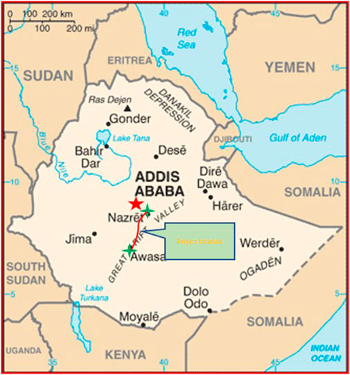
FIGURE 1. Geological map along the MH Highway.
There are many ground fissures along the MH Highway on the floor of the Ethiopian Rift Valley, most of which are secondary faults of the rift. These fractures are relatively short in extension and small in scale. Ground fissures were developed at 600 m to the right of main K169+600, the Arsi Negele connecting line, and the Shashemene connecting line. Basically, these upright fractures, with about 60–200 m length, 5–8 m width or so, and visibly 8–10 m depth, are the culprit of country road cracks. Moreover, a series of depressions and collapse pits are distributed like a string of beads in the K180 interchange area of the MH Highway.
3 Characteristics of ground fissures
3.1 Distribution and morphological characteristics of ground fissures
Ground fissures are widespread within the research area, most of which are secondary faults of the rift. These fractures are relatively short in extension and small in scale. The main locations and characteristics of 11 ground fissures discovered through investigation are listed in Table 1.
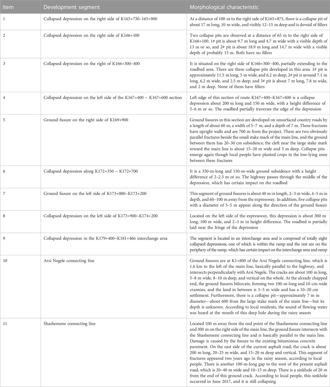
TABLE 1. Location and morphological characteristics of ground fissures in the research area.
From the surface manifestation of fractures as a whole, it can be seen that the ground fissures in the research area can be divided into two types: exposed fissures and concealed fissures, which have the following characteristics.
3.1.1 Exposed fissures
Exposed ground fissures are divided into two types. As shown in Figure 2, the first type is the surface crack of linear extension, mostly horizontally ripped, and the stratigraphic dislocation on both sides is not obvious. It is generally 5.0–10.0 m wide, and the wall on each side is usually upright and takes on a wedge-shaped pattern of being wide at the top and narrow at the bottom in the profile. Generally, the depth from the surface to the fracture closure can reach a maximum of 20.0 m or so, and the fracture has a noticeable stretching direction. Figure 3 shows that the exposed fissure of the Arsi Negele connecting line linearly spreads from NW to SE in the same direction of the main Rift Valley’s tectonic line, indicating that the main Rift Valley structure has a significant controlling effect on the development of fractures.
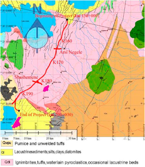
FIGURE 2. Geographical location map of the MH Highway.
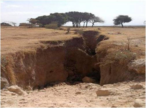
FIGURE 3. Arsi Negele exposed fissures.
The second type, as illustrated in Figure 4, presents a stripped collapse zone, and the strip extends in the direction of the main Rift Valley’s tectonic line, mostly represented by vertical subsidence. Such zones vary in widths and have a certain height difference with the original surface. The investigation reveals that this zone is covered with a sedimentary formation of certain thickness, suggesting that it is formed by the collapse of the stratum on both sides of the first type, namely, exposed fissure, after it becomes relatively stable in the later stage. The collapse zone of the outcrop-type ground fissure at the Shashemene connecting line shown in Figure 2 is about 100 m long, 20–40 m wide, and 10–15 m deep. According to local people, the pit began to appear in June 2017. The depth of the pit is about 15 m, indicating that the sinkhole zone has been reactivated.
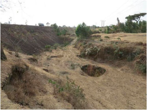
FIGURE 4. Shashemene exposed fissures.
3.1.2 Concealed fissures
Concealed fissures are manifested as collapsed depressions in the plane modality. In a plane, it takes on the shape of an ellipse. The middle of the depression is wide and gentle, and the height difference with the periphery of the depression is normally 1.0–3.0 m. In the depressions, there often exist string-bead-like ground collapse pits, rounded on the surface and varying in diameters, and the maximum depth measures up to 10.0 m. As shown in Figure 5, the depression on the right side of the roadbed of the K165+700∼K166+450 section is about 500 m long, 50–80 m wide, and 6–8 m in height difference. Three collapse pits are observed on the right side of K166+300-400, which have a diameter of 3–5 m and a depth of about 4–5 m, and are only 10 m from the side boundary of the roadbed.
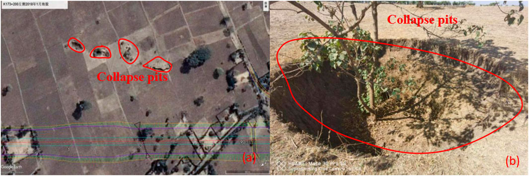
FIGURE 5. String-bead-shaped collapse pits on the right side of K166+300-400.
The collapsed depressions are elliptically distributed in the plane, and their long-axis direction coincides with the structural trend of the main Rift Valley. There are eight collapsed depressions in the interchange area of K179+400∼K181+466, as shown in Figure 6. A geophysical survey reveals that the depressions are interconnected by several parallel fissures, and the overall direction of the ground fissures is N45°E, which is consistent with the direction of the main Rift Valley structure, except for partial intersections.
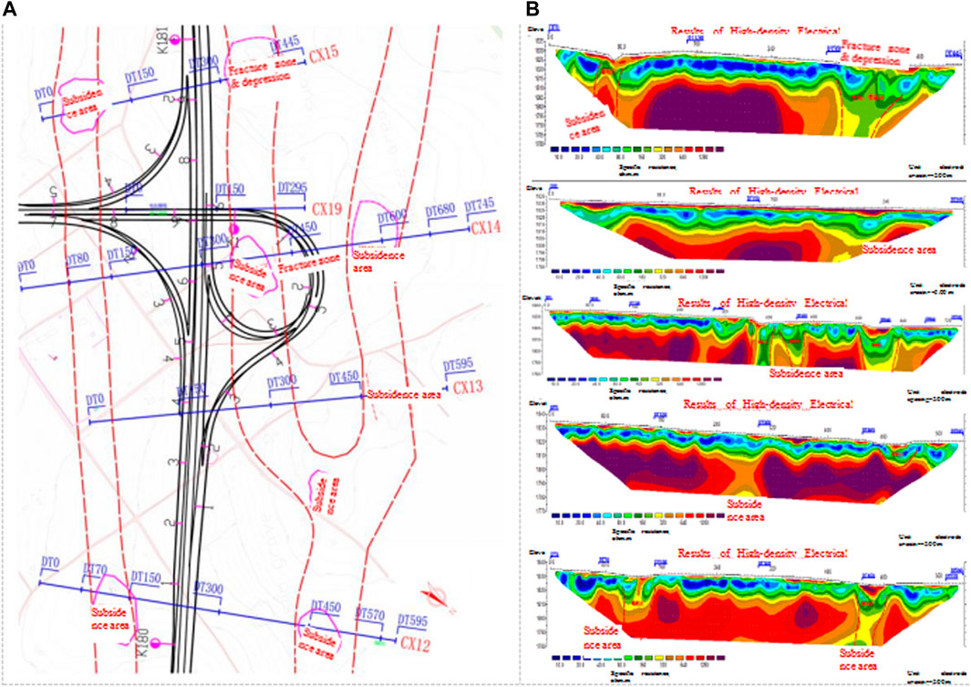
FIGURE 6. Comprehensive geophysical prospecting result map of the K179+400∼K181+466 interchange area.
The ground cracks are currently exposed and concealed. The causes are the same. They are caused by the geological structure, but they are different in the form of expression.
3.2 Characteristics of ground fissure activity
3.2.1 Characteristics of ground fissure activity
Figure 7 illustrates the multi-year development characteristics of ground fissures in the vicinity of the Arsi Negele connecting line for the period 2004–2020. From the pictures, it can be seen that in 2004, there was a band-shaped collapse zone in the area, and distinct collapse and ground fissures had not appeared yet; in 2013, small-scale collapse pits and ground fissures appeared on both sides of the road; in 2017, these cracks kept developing, extending, and widening to the degree that existing roads were cut off and greatly damaged; and in 2020, the roads cracked again under the action of ground fissures despite being repaired and backfilled. Overall, the ground fissures remain in a state of developmental activity at the macro level. Therefore, from the changes in the cracks on the surface, it can be seen that the cracks on the ground are gradually developing and changing over time.
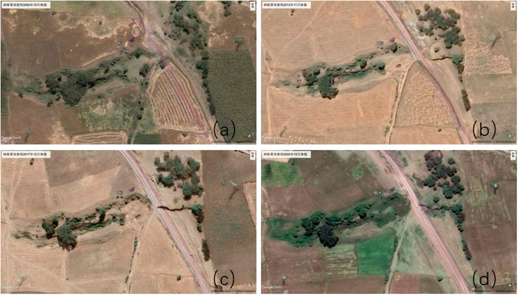
FIGURE 7. Ground fissure development of the Arsi Negele connecting line: (A) remote sensing images, October 2004; (B) satellite remote sensing images, November; (C) remote sensing images, December 2017; and (D) remote sensing images, October.
3.2.2 Seasonal characteristics of ground fissure activity
It can be inferred from the investigation and exploration results that the ground fissure activity has seasonal characteristics in the time series. To be more specific, their development is not obvious in the dry season, but they often showcase the features of sudden destruction or intensified development in the rainy season (National meteorological Agency of Ethiopia, 2001). In addition, short-term heavy rainfall will often lead to the reopening of concealed fissures or the formation of collapse pits, such as the Shashemene connecting line ground fissure. The ground fissure of the Arsi Negele connecting line developed at a faster pace and damaged the road after a strong rainfall in June 2017; the ground fissure at 700 m on the right of the main line K169+900 had not taken shape before May 2016, but a new ground fissure with a width of 5.0 m and a depth of 7.0 m formed at this location after a continuous heavy rainfall.
3.3 Geophysical characteristics of the ground fissure zone
The bedrock in the research area is dominated by tuffs, and the surface is mostly covered by the loose Quaternary overburden. The binary stratigraphic texture is simple, and the stratigraphic physical parameters are relatively stable and continuous. While in the locations where ground fissures and crevices are developed, the ground fissures cause discontinuities in the original stratigraphy or affect the geophysical characteristics of the rock and soil bodies situated in a certain range around them, such as forming geophysical anomalies, a condition good for geophysical prospecting (Wang and Liu, 2003a; Wang and Liu, 2003b; Wang and Liu, 2004). In this study, electrical prospecting and radon gas testing were carried out in the ground fissure area.
3.3.1 Electrical characteristics
The electrical prospecting results report that in the area without fracture distribution, the apparent resistivity value generally follows the rule of low to high from shallow to deep stratum, which is basically identical with the binary structure characteristics of the stratum, while the apparent resistivity of the area with developed fractures is notably different from the background field of the resistivity of surrounding strata. For exposed fissures, the apparent resistivity anomalies are generally high in the upper unfilled depth range at the center of the fracture, and the concealed fractures on the other hand present a remarkable zone of low-resistance anomalies.
Figure 8 shows the vertical electrical prospecting rate profile along the concealed fissure in the interchange area from K179+400 to K181+466. According to the exploration results, there are low-resistance anomalies in the DT230−DT310 and DT550−DT640 sections, both low-lying and having obvious collapse pits, which are thus deciphered as ground fissure development zones.
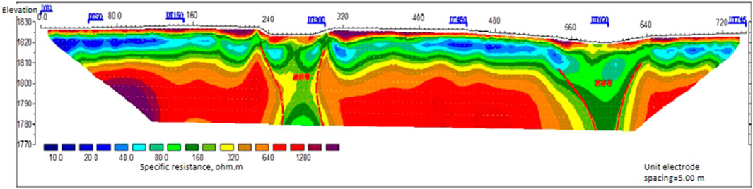
FIGURE 8. Typical profile of high-density electrical method in the K179+400∼K181+466 interchange area.
3.3.2 Radon gas characteristics
The fracture zone in the research area is a good migration channel for groundwater and gas, and the stratum contains thick, porous, and broken tuff. As a result, radon gas can easily leak out from depths to the surface, providing favorable geophysical conditions for inferring the development and distribution of ground fissures through radon gas concentration. The radon gas test carried out in the ground fissure development area demonstrates that the background value of the radon gas concentration in the research area is generally high, that is, 103–104 Bq·m-3 in the order of magnitude, but there are massive radon gas concentration anomalies in the vicinity of the fractures.
Figure 9 shows the radon gas test profile of the K179+400∼K181+466 interchange area arranged perpendicular to ground fissures. The test results show that the radon gas concentration is not highly abnormal near the development position of exposed ground fissures or collapse pits. This is mainly because the ground fissures are underground radon gas escape channels, but as the ground fissures have developed to the surface, radon gas in the soil leaks to the air, causing the radon gas value at the place directly above the fissures to be slightly lower than that of surrounding areas. So, the radon concentration curve at the location of the fissure is “M”-shaped. Around the fracture zone, the radon concentration will rise steeply, generally more than twice the background value, forming an anomaly zone of high radon concentration. The radon concentration profile fairly reflects the location of ground fissures. In this profile, two radon gas concentration anomalies exist within survey lines DQ40−DQ80 and DQ310−DQ400, wherein DQ40−DQ80 is the location of the collapse pit and DQ310−DQ400 is the location of the fracture zone where the rock masses are shattered and prone to collapse.
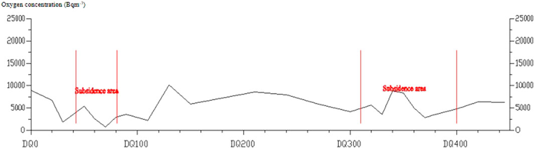
FIGURE 9. Typical profile of the radon gas test in the K179+400∼K181+466 interchange area.
3.4 Stratigraphic texture characteristics of the ground fissure area
Drilling and trenching the collapsed depression on the right of the section K165+700∼K166+450 in the research area are implemented, as shown in Figure 10. The typical drilling results show that the overlying soil is mainly loose, powdery clay and silt, and the core of the lower bedrock, namely, tuff, is basically fragmented, cracked, and porous. Among them, there is a loose layer emerging 9–19 m of the ZK4-1 borehole, and the drilling speed is fast. Other boreholes on the external side of the roadbed do not show any abnormality, which is judged to be the result of filling the main fracture with clay.
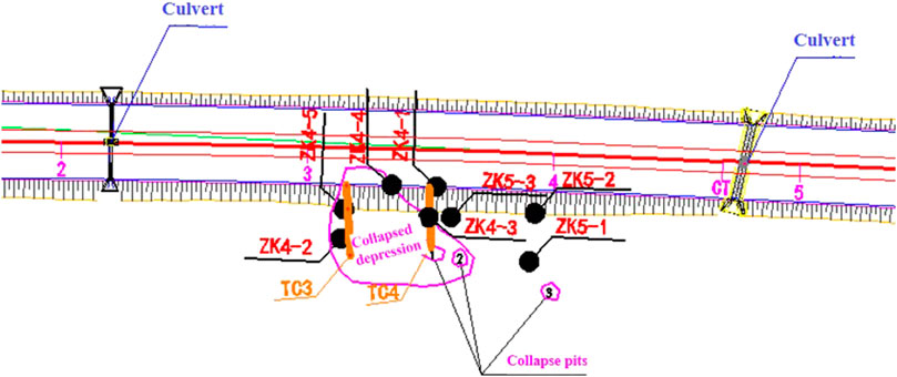
FIGURE 10. Exploration layout of the collapsed depression on the right side of the K165+700∼K166+450 section.
Trenching was carried out in the middle of the concealed fissure in section K166+300–k166+400. From the T3 trench in Figure 11, it can be seen that there are traces of developed fractures, mostly filled with gray clay. The engineering geological profile of the trench in Figure 12 reveals that the surface layer of the ground is covered with powdery clay, which is about 1–2 m thick at both ends, gradually deepening from the middle part until a maximum of 4 m. At the same time, there is a silt layer deposited at the lower part of the thickest part of the silty clay, as thick as 2 m in the middle, disappearing gradually on both sides. It can be seen that there are signs of later deposition in the stratum exposed in the middle of the trench.
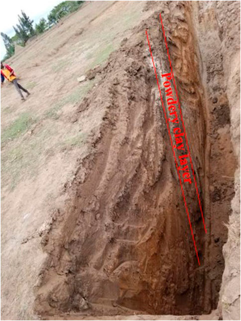
FIGURE 11. TC3 trench.
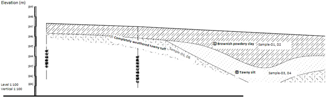
FIGURE 12. Engineering geological profile of the TC3 trench.
The photograph of the TC4 trench in Figure 13 reveals that there are two collapse pits. During the wet season, the surface water converges into No. 1 collapse pit and flows away from its bottom, but the sound of the water flow can be heard in No. 2 collapse pit, implying that the bottoms of the two pits are unblocked. In addition, near No. 1 collapse pit, a small hollow with a depth of about 4 m and a fissure penetrating the ground are found in trench TC4. The engineering geological profile of the TC4 trench shows that the surface overburden is 1–2 m and composed of thick powdery clay, as shown in Figure 14. On the left side of the trench is a stratum consisting of only powdery clay and completely weathered tuff; in the transition to No. 1 collapse pit, a silt layer with a maximum thickness of about 2.5 m gradually appears. This is also caused by later collapse deposition.
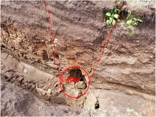
FIGURE 13. TC4 trench.
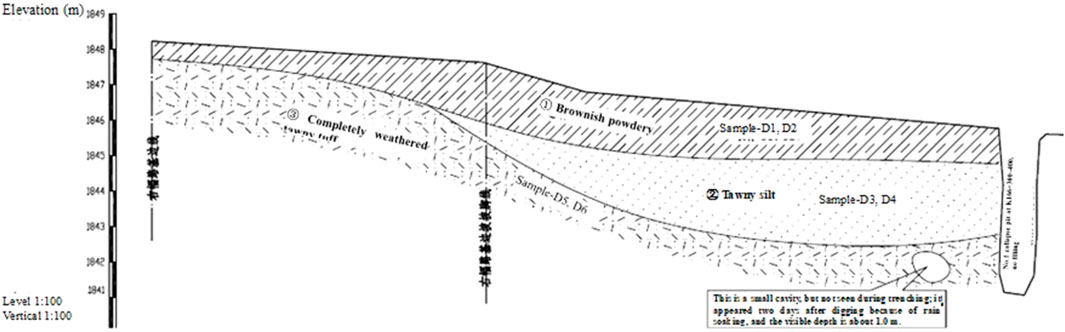
FIGURE 14. Engineering geological profile of the TC4 trench.
4 Exploration on the causes of ground fissures and deformation mechanism
The formation and deformation processes of ground fissures in the Ethiopian Rift Valley are closely related to the strong tectonic activity of the basement, the stratigraphic texture, and the infiltration of precipitation. In general, the violent tensile and tectonic movement of the basement is the main controlling factor in the formation of ground fissures; unfavorable stratigraphic textures provide conditions for the formation of ground fissures; and heavy rainfall infiltration intensifies the formation process of ground fissures and exhibits different development patterns (Ayalew et al., 2004; Roberts et al., 2012).
4.1 Geological structure action
Ground fissures can be divided into tectonic fractures and non-tectonic fractures in terms of formation conditions. The Ethiopian Rift Valley area has a high incidence of ground fissures, which is bound up with the distribution of widely developed fractures in the valley (China Water&Power Press, 1980; Zhang, 1980). It is a typical area of tectonic fractures. Laike Mariana Asfaw (1982) investigated the distribution, generation, and development of ground fissures in Ethiopia from geological, geophysical, and tectonic aspects, compared and analyzed the ground fissures in the area with the seismic data of the same period, and concluded that the generation of ground fissures is influenced by the geological structure. Williams (2020) studied the scale and age of the tensional fracture swarm in the north of the Ethiopian Grand Canyon and arrived at the conclusion that the ground fissures are associated with the expansion of the East African Great Rift Valley.
The consistency of the planar distribution pattern and spreading direction of the ground fissures in the research area with the fault structure of the basement indicates that the basement structure appreciably controls the evolution of the ground fissures. It is the ferocious tensioning and priming of the basal geological structure that forms the basis for ground fissures, and the slow creeping expansion of the basement structure that leads to the tensional cracking of the overlying stratum is the main controlling factor of the occurrence of ground fissures in the research area.
4.2 Effects of stratigraphic texture
The surface overburden in the research area is dominated by silt, sandy soil, and breccia, which has the characteristics of a thin soil body, a large pore ratio, poor grading, a loose structure, and high permeability; the central rock mass is mostly composed of soft ignimbrite but with hidden tectonic fractures; the lower rock mass, being low in diagenetic grade, is where tensional fractures, cracks, and cavities are scattered and groundwater runoff channels are formed. According to the investigation, there are dense bedrock fractures in the research area, with an aperture varying from 3 mm to 200 mm (Cao and Li, 1986; Wang et al., 1986). The monotonous stratigraphic texture and the fractures and cavities in the underlying stratum provide an environment for water infiltration and creep, creating conditions for surface fissures and collapses.
On the right collapse depression of K165+700∼K166+450, 11 holes were drilled in the section of the highway. The drilling results revealed that a hole of 30 cm was found in the lower part of the collapse depression during drilling, with water leakage and no filling. Other boreholes in the vicinity were in a normal state, indicating that the cavities exist only in low-lying areas and have no impact on the roadbed and its vicinity.
Figure 15 shows an isobath map of the clay blanket in the collapsed depression, where the thickness of clay in the collapsed depression takes on a pot-bottom shape, indicating that it was formed due to the sedimentation of clay at a later stage.
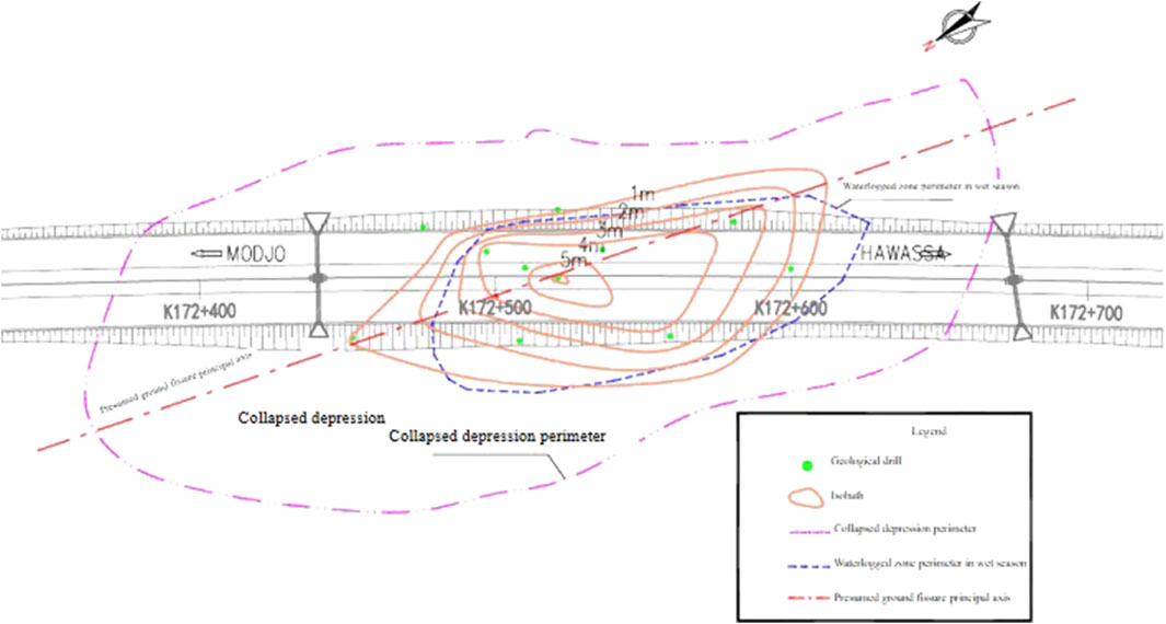
FIGURE 15. Isobath map of the upper clay layer of the collapsed depression in the K165+700∼K166+450 section.
4.3 Effects of precipitation and water infiltration
The results of investigation in the research area suggest that the average annual rainfall in the ground fissure zones in the research area exceeds 400 mm (Geological Survey of Ethiopia). Meanwhile, the development of ground fissures is closely related to the process of short-term heavy rainfall, which may lead to the reopening of hidden fractures or the formation of collapse pits, indicating that rainfall constitutes an important causative factor of ground fissure development and deformation.
According to the surveys and visits paid to local residents, copious ground fissures in the research area are generated after acute heavy rainfall, such as the cracks at 700 m on the right side of the main line K169+900, of the Shashemene connecting line, and on the east side of the existing asphalt road. Moreover, at the investigation site, during the trenching near the concealed fissures of the K166+300 section, no obvious cavity was observed at the beginning of excavation. After the strong rainfall in this area, the soil about 2 m deep below the ground appeared to have collapsed into a hollow under the action of hydrodynamic force, and the hole became larger with the increase in rainwash time; at the same time, the sound of water flow was heard in the void, indicating that there was an unimpeded runoff channel beneath it.
As it can be inferred from the phenomenon of rain water converging into overland runoff, the surface water in the research area is mainly recharged by atmospheric precipitation. Due to the special stratigraphic texture of the project area, the surface water permeates rapidly through the loose sedimentary mantle and a great many bedrock fissures and quickly infiltrates and disappears even within a short period of time after heavy rainfall. In the process of infiltration along the cracks, the soil on both sides is scoured and eroded, and the fine particles are migrated through the underlying bedrock crevices, which damages the structure of the soil, loosens or destroys the soil, leads to the formation of cracks or pits, and gradually enlarges the opening of the cracks.
From the stratigraphic conditions revealed by drilling and trenching, it can be seen that underground erosion also occurred in the area of ground fissures. Wang Xiuyan and Liu Changli considered that if the soil inhomogeneity coefficient is greater than 10, the ratio of permeability coefficients of the upper and lower contact soils is higher than 2, and the seepage hydraulic gradient is larger than the critical hydraulic gradient of underground erosion (the hydraulic gradient is usually considered >5). It is susceptible to leakage and water creep (2003−2004). The stratigraphic conditions in the research area are basically same as the conditions for the occurrence of underground erosion, and the cavities exposed by trenching also prove the existence of underground erosion in the lower part.
4.4 Evolutionary characteristics of ground fissures
According to the stratigraphic texture revealed by trenching, the formation process of ground fissures can be analyzed as follows: first, under the action of tectonic movement and heavy rainfall, outcrop-type cracks are generated. Then, the loose soil begins to subside from the edges of the crack, and the topsoil on both sides will migrate and deposit to the fracture zone. As the composition of the clay granules is carried away by water, a sedimentary silty layer that is thin on the periphery and thick in the middle forms in the center of the fracture. Meanwhile, under relatively stable fracture activities, the fracture zone gradually develops into a collapsed depression, the middle part of which is easily accumulated with water that seeps into the openings of the ground fissures to generate a passage, causing the soil at the upper part of the fracture to subside. This is how collapse pits are formed. As a result, the surrounding soil is further and repeatedly accumulated and carried to the middle low-lying area to expand the collapse pits gradually. Figure 16 shows the ground fissure evolution. Moreover, the development and evolution of ground fissures in the research area are recurrent in nature.
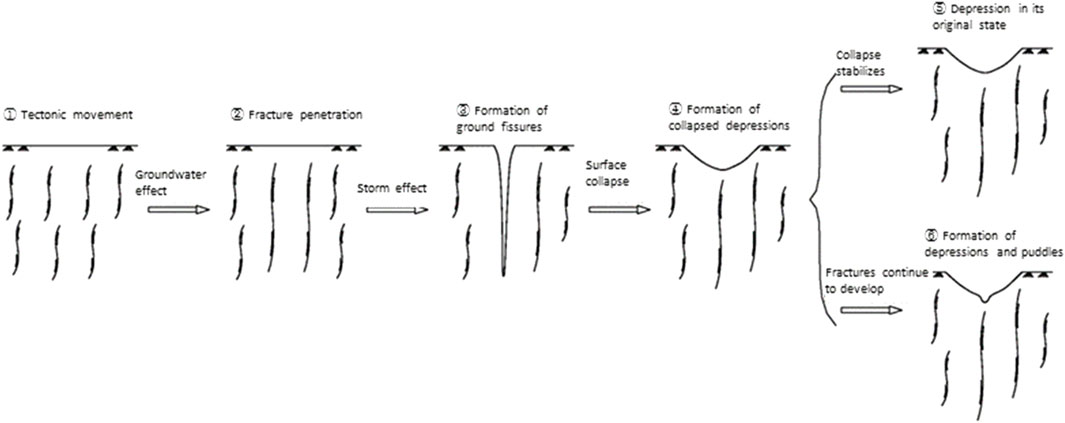
FIGURE 16. Diagram of ground fissure evolution.
5 Conclusion
The main conclusions drawn by studying the ground fissures on the MH Highway in the Ethiopian Rift Valley are as follows:
1) The ground fissures are divided into two types: exposed fissures and concealed fissures, whose distribution and direction are closely related to the distribution of geological structures. The exposed fissures are crevasses or stripped collapse zones, and the concealed fissures are collapsed depressions and string-bead-like collapse pits.
2) The ground fissures are highly active, and their development process presents strong seasonal characteristics, that is, emerging or developing in the rainy season.
3) The ground fissures have significant geophysical anomalies, which are mainly manifested as low-resistance anomalies and radon gas anomalies through field exploration.
4) The violent tectonic activity of the basement (expansion of the East African Rift Valley) plays a controlling role in the generation of ground fissures. Meanwhile, adverse stratigraphic textures provide basic conditions for the development of ground fissures, and the infiltration and underground erosion resulting from heavy precipitation are important factors to aggravate the development of ground fissures.
5) In the ground cracks and collapse areas, the route should be taken as far as possible. For areas that cannot be avoided, try to adopt the form of roadbeds. Reinforcement should be performed during the process of road processing. If the bridge is needed, appropriate reinforcement and preventive measures should be taken to regularly monitor and adjust in time. The influence and erosion of groundwater are important causes of the induction of ground crack development and collapse. It is recommended to note ground drainage and flow measures in the cracks and collapse areas to limit the mining of groundwater.
Data availability statement
The original contributions presented in the study are included in the article/Supplementary Material; further inquiries can be directed to the corresponding author.
Author contributions
WL contributed to the preparation of the article through on-site investigation and data analysis, CX contributed to the preparation of the article, and XH modified the content of the article. All the authors discussed the results and edited the manuscript.
Conflict of interest
Xi'an China Highway Geotechnical Engineering CO., LTD is a wholly-owned subsidiary of CCCC First Highway Consultants CO., LTD. Authors XU Cheng and HUANG Xiaonian are/were employed by Xi'an China Highway Geotechnical Engineering CO., LTD.
The remaining authors declare that the research was conducted in the absence of any commercial or financial relationships that could be construed as a potential conflict of interest.
Publisher’s note
All claims expressed in this article are solely those of the authors and do not necessarily represent those of their affiliated organizations, or those of the publisher, the editors, and the reviewers. Any product that may be evaluated in this article, or claim that may be made by its manufacturer, is not guaranteed or endorsed by the publisher.
References
Asfaw, L. (1982). Development of earthquake-induced fissures in the main Ethiopian rift. Nature 297, 393–395. doi:10.1038/297393a0
Ayalew, L., Yamagishi, H., and Reik, G. (2004). Ground cracks in Ethiopian Rift Valley: Facts and uncertainties. Eng. Geol. 75, 309–324. doi:10.1016/j.enggeo.2004.06.018
Cao, W., and Li, K. (1986). An indoor research method for the process of water release, absorption and transfluence in clayey soil layers due to water level rise and fall. Site Investigation Sci. Technol. (4), 22–28.
China Water&Power Press (1980)., 1. Nanjing, Jiangsu: China Water&Power Press, 118–136.Soil mechanics teaching and research office of east China technical university of water resources, Geotechnical Principles and Calculations.
Chorowicz, J., Collet, B., Bonavia, F., Mohr, P., Parrot, J. F., and Korme, T. (1998). The Tana basin, Ethiopia: Intra-plateau uplift, rifting and subsidence. Tectonophysics 295, 351–367. doi:10.1016/s0040-1951(98)00128-0
Chorowicz, J. (2005). The East African rift system. J. Afr. Earth Sci. 43, 379–410. doi:10.1016/j.jafrearsci.2005.07.019
Ebinger, C. J. (1989). Tectonic development of the Western branch of the East African rift system. Geol. Soc. Am. Bull. 101, 885–903. doi:10.1130/0016-7606(1989)101<0885:tdotwb>2.3.co;2
Ebinger, C. J., Yemane, T., Harding, D. J., Tesfaye, S., Kelley, S., and Rex, D. C. (2000). Rift deflection, migration, and propagation: Linkage of the Ethiopian and Eastern rifts, Africa. Afr. Geol. Soc. Am. Bull. 112, 163–176. doi:10.1130/0016-7606(2000)112<163:rdmapl>2.0.co;2
Hoffman, C., Courtillot, V., Feraud, G., Rochette, P., Yirgu, G., Ketefo, E., et al. (1997). Timing of the Ethiopian flood basalt event: Implications for plume birth and global change. Nature 389, 838–841. doi:10.1038/39853
Ministry of Mines (1976). Regional geoloSSSgical map of Ethiopia (1:250,000). Addis Ababa, Ethiopia: Geological Survery of Ethiopia.
National meteorological Agency of Ethiopia (2001). Rainfall data for langona and Arsi Negele meteorological stations. Addis Ababa, Ethiopia: National meteorological Agency of Ethiopia.
Roberts, E. M., Stevens, N. J., O'Connor, P. M., Disks, P. H. G. M., Gottfried, M. D., Clyde, W. C., et al. (2012). Initiation of the Western branch of the East African Rift coeval with the eastern branch. Nat. Geosci. 5, 289–294. doi:10.1038/ngeo1432
Wang, X., and Liu, C. (2003a). A new understanding of the pore water infiltration law of cohesive soil. Acta Geosci. Sin. 1, 91–95.
Wang, X., and Liu, C. (2003b). Exploration on the law of water permeation and release of deep cohesive soil. Chin. J. Geotechnical Eng. (3), 308–312.
Wang, X., and Liu, C. (2004). Seepage law of pore water in low permeability media. J. Eng. Geol. 1004.
Wang, Z., Sun, G., Liu, S., Zhu, X., Tang, G., and Huang, S. (1986). Geotechnical testing techniques. Beijing, China: China Architecture & Building Press, 61–78.
Williams, F. M. (2020). Safeguarding geoheritage in Ethiopia: Challenges faced and the role of geotourism. Geoheritage 12, 31. doi:10.1007/s12371-020-00436-9
Williams, F. M., Williams, M. A. J., and Aumento, F. (2004). Tensional fissures and crustal extension rates in the northern part of the Main Ethiopian Rift. J. Afr. Earth Sci. 38, 183–197. doi:10.1016/j.jafrearsci.2003.10.007
Wilson, M., and Nyambok, I. O. (2000). Ground subsidence and its socio-economic implications on the population: A case study of the nakuru area in central Rift Valley, Kenya. Environ. Geol. 39 (6), 567–574. doi:10.1007/s002540050468
Keywords: Ethiopian Rift Valley, ground fissure, highway, developmental characteristics, deformation mechanism
Citation: Liu W, Xu C and Huang X (2023) Brief analysis of the development characteristics and deformation mechanism of ground fissures on the MH Highway in the Ethiopian Rift Valley. Front. Earth Sci. 10:1107094. doi: 10.3389/feart.2022.1107094
Received: 24 November 2022; Accepted: 28 December 2022;
Published: 26 January 2023.
Edited by:
Haijun Qiu, Northwest University, ChinaReviewed by:
Suli Cui, Northwest University, ChinaPeifen Xu, Institute of Geology and Geophysics (CAS), China
Copyright © 2023 Liu, Xu and Huang. This is an open-access article distributed under the terms of the Creative Commons Attribution License (CC BY). The use, distribution or reproduction in other forums is permitted, provided the original author(s) and the copyright owner(s) are credited and that the original publication in this journal is cited, in accordance with accepted academic practice. No use, distribution or reproduction is permitted which does not comply with these terms.
*Correspondence: Weimin Liu, xaliuweiming1971@126.com