Characteristics of Stress Field and Damage Law of Coal Rock in Residual Pillar of Top Slice and Its Application
 Fengfeng Wu1,2
  Xin Yu
- 1School of Mines, China University of Mining and Technology, Xuzhou, China
- 2State Key Laboratory of Coal Resources and Safe Mining, China University of Mining and Technology, Xuzhou, China
- 3Shanxi Yangcheng Shancheng Coal Industry Co., Ltd., Jincheng, China
This article presents a theoretical analysis and numerical simulation studies to determine the suitable position for the lower slice roadway in a residual pillar area after top slicing a thick coal seam. We considered the load concentration on the coal pillar, the goaf floor, and the stress distribution characteristics of the coal pillar area before and after the top slice. With a mechanical model built of the residual pillar load propagation in the floor and the failure model of the floor surrounding rock, the analytical formula we deduced for the coal pillar floor stress and the expression of the floor failure depth of the roadway provides a basis for the reasonable determination of the position of the lower slicing roadway. Studies proved that after mining the top slice working face, the floor stress field of the residual pillar area presented characteristics of the non-uniform distribution. The stress concentration occurred below the coal pillar. The stress variation area appeared at the edge of the coal pillar, with a stable stress area appearing far away from the coal pillar area. Therefore, the roadway layout should avoid the areas below the coal pillar and the coal pillar edge with high stress levels and a large stress variation gradient. High stress concentration formed on the coal pillar transferred to the lower layered coal and floor strata, and decreased the stress concentrations layer by layer. However, mining of the top-layered working face affected the coal, and rock mass damaged the coal pillar floor area and weakened the mechanical properties, which was not conducive to the control of the roadway surrounding rock. The research results applied to No. 30117 working face of the lower slice of the Shancheng Coal Industry, and the proper position of the return airway of the working face was determined to be 8 m outside the east side of the residual pillar in the top slice, achieving a good surrounding rock control effect.
Introduction
In Chinese coal reserves, thick coal seams account for more than 40% of the total resources and account for more than 50% of the coal production (Wang, 2009; Dai et al., 2013). Thick coal seam mining technology has experienced three gradual optimization stages: layered mining, top coal caving mining, and large mining height mining (Zhang, 2001; Wang and Zhong, 2008). However, due to the problems of different sizes of coal enterprises, unbalanced development of mining technology, and complex coal seam occurrences (Xu, 2003; Bai et al., 2014, 2017), many thick coal seam mines in Datong, Huainan, Chifeng, and other mining areas in China are still adopting layered mining technology, while in Jincheng and other mining areas, there is a situation of top-layered mining and bottom-layered re-mining. For the downward mining working face of a thick coal seam, the lower layered coal becomes affected by the top-layered mining, leaving a coal pillar; the stress environment is complex, seriously damaging the surrounding rock. Therefore, it was vital to clarify the stress distribution characteristics and damage law of the surrounding rock under the residual coal pillar to determine the lower layered roadway’s reasonable spatial layout.
Many scholars have studied the stress field characteristics and coal rock damage law of the left coal pillar area. Mu et al. (2021) constructed a mechanical model of the left coal pillar in close coal seam mining and found that the left coal pillar was the main reason for the stress concentration of the lower coal seam roadway. Tian et al. (2019) studied the stress evolution law of the lower coal seam under the influence of coal pillar disturbance after upper coal seam mining using the combination of physical and numerical simulations. Liu et al. (2016) studied the stress distribution characteristics of the residual coal pillar floor. They proposed that the stress in the coal pillar area is proportional to the abutment pressure on the coal pillar, inversely proportional to the vertical distance and diffusion angle, and extends elliptically along the direction of gravity. Yue et al. (2021) constructed the structural mechanics model of “elliptical stress arch” in the overlying coal seam and calculated the additional mining stress of the floor roadway under the left coal pillar. Zhao et al. (2020, 2021a, 2021b) studied the damage and failure characteristics and the stress distribution characteristics of floor strata under isolated island coal pillars and analyzed the asymmetric deformation mechanism of the lower layered roadway. Huang et al. (2019, 2020, 2021) studied the three-field evolution characteristics of close coal seam mining using the numerical simulation, established a coupling control model of the stress field, displacement field, and fracture field and proposed a reasonable calculation method of the lower roadway position. Shen et al. (2018) put forward the “three index method” of the roadway layout under the left coal pillar. They pointed out that the lower layered roadway was preferentially arranged in the area of 0 ≤ stress concentration coefficient (ratio of local stress to original material rock stress) ≤ 1, 0.8 ≤ coefficient of horizontal pressure (ratio of horizontal stress to vertical stress) ≤ 1.4, and 0 ≤ stress gradient ≤1. Many scholars have studied the stress distribution and the failure zone of the floor under the load effect of the coal pillar, but there is little research on the stress field characteristics of the floor rock and the damage law of the surrounding rock under the condition of the top slicing mining and the lower slicing mining, which did not lead to solve the problem of the roadway layout under this condition.
Based on the existing research, this study takes the 30117 lower layers working face of the Shancheng Coal Industry as the engineering background, and established the calculation model of the load concentration of the top-layered left coal pillar and the goaf, used theoretical analysis and numerical simulation to derive the analytical formula of the stress of the coal pillar floor, and analyzed the distribution characteristics of the stress field. Finally, based on slip line theory, the coal and rock damage law under the coal pillar’s influence was studied, providing a theoretical basis for the proper location selection of the lower layer roadway.
Engineering Background
Position of Working Face and Surrounding Mining Situation
The Shancheng Coal Industry is located in Beiliu town, Yangcheng County, Shanxi Province, with a production capacity of 0.6 Mt/a, belonging to medium-sized mines, mainly mining the No. 3 coal seam. The No. 3 coal seam thickness is 5.43 ∼ 6.60 m, the average thickness is 6.24 m, and the dip angle is 1 ∼ 4°. Historically, the No. 3 coal seam mining was only the top layer, and the mining height was 2.3 m. However, it has the lower layer working face mining of 30117 located in 301 mining areas. Therefore, the goaf of 30105 top layer working face is above the working face, the goaf of 30,106 top layer working face is on the right, and the goaf of 30104 top layer working face is on the left. Figure 1 shows the underground relative position relationship of the 30117 working face.
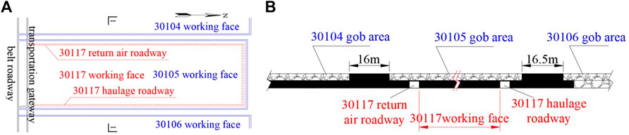
FIGURE 1. Position of the working face and surrounding mining situation. (A) plan view, (B) I-I section view.
Characteristics of Coal Seam and Roof–Floor Strata
Figure 2 gives the comprehensive geological column of the No. 3 coal seam. The direct roof of the No. 3 coal seam is mudstone, siltstone, coal grained, and fine-grained sandstone strip with an average thickness of 2.79 m; the direct floor is mudstone with an average thickness of 2.48 m. According to the data provided by the mine production geological report, the physical and mechanical parameters of the No. 3 coal seam and roof and floor strata are in Table 1.
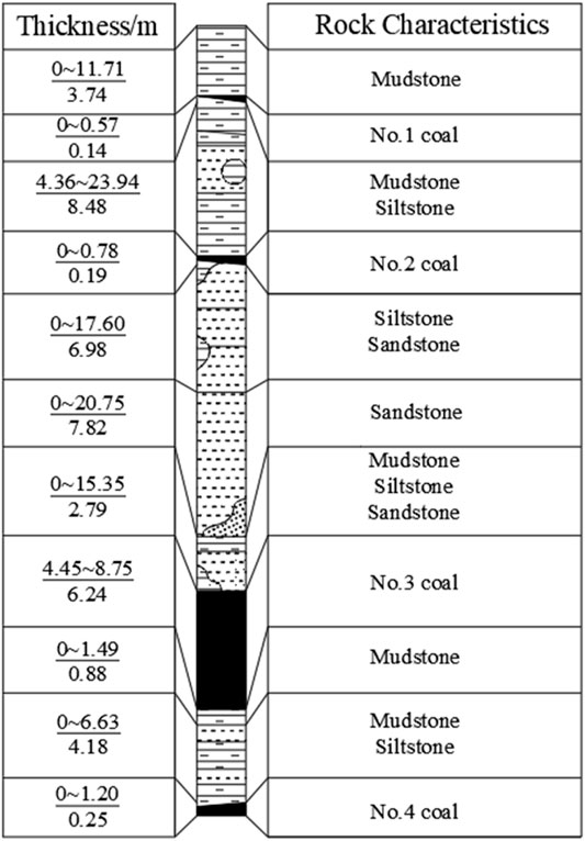
FIGURE 2. Comprehensive geological histogram of coal seam.
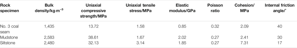
TABLE 1. Test results of physical and mechanical properties parameters of the No. 3 coal seam and roof–floor strata.
Test Results of Ground Stress
The ground stress test results of the No. 3 coal seam are in Table 2. The vertical stress in the area near the 30117 working face is much higher than the horizontal stress, which varied from 12.42 to 21.42 MPa.
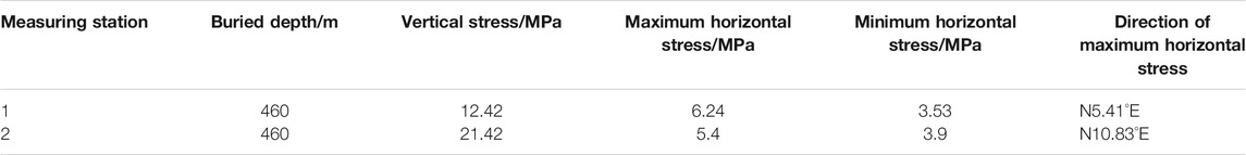
TABLE 2. Test results of hydraulic fracturing stress.
Load Concentration Calculation of Residual Pillar and Lower Layer
With mining the top layer working face, the roof strata were broken, moved, and deformed, and finally, the masonry beam structures were formed to bear the upper rock. Figure 3 shows the load on the coal pillar from the weight of the overlying strata and the exposed strata on one or both sides of the coal pillar transferred to the coal pillar.
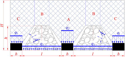
FIGURE 3. Schematic diagram of coal pillar load calculation under incomplete collapse.
As seen in Figure 3, with mining of one side of the coal pillar, its weight bears mainly on the rock layer in the C area, and then load concentration q1 on the coal pillar is as follows:
The mining of the two side sections of the coal pillar mainly undertakes the weight of the rock layer in the area A. The load set q2 on the coal pillar is as follows:
The load concentration q3 of the goaf floor is as follows:
where b is the section width of the coal pillar, m; h is the rock roof caving height, m; and α is the caving angle of strata overlying goaf.
Distribution Characteristics of the Stress Field in the Residual Pillar Area
Analysis Based on Elastoplastic Theory
Mining of the top slice working face caused the redistribution of the surrounding rock stress. Additionally, causing the stress concentration of the coal and rock mass around the mining space will also transfer the stress to the deep floor through the remaining coal pillars. Therefore, simplifying the coal rock assembly to a homogeneous elastic body makes the stress distribution of the coal seam floor to the case of uniform load q acting on the semi-infinite plane, and the mechanical model of the residual coal pillar load propagating in the floor strata after stratified mining becomes as shown in Figure 4.
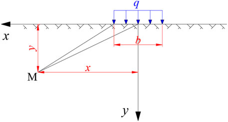
FIGURE 4. Mechanical model of coal pillar load propagating in floor strata.
Using the elastic theory (Xu, 1979), the stress calculation at any point M in the bottom rock under uniform load on the free boundary was done by using the superposition principle:
where σx is the positive stress along the horizontal direction, MPa; σy is the normal stress along the vertical path, MPa; τxy is the shearing stress, MPa; q is the uniform load on the coal pillar, kN/m; x is the horizontal distance from point M to the coal pillar center, m; and y is the vertical distance from point M to the coal pillar center, m.
The earlier equations show that the stress at any point in the floor strata mainly depends on the load of the upper coal pillar, the width of the coal pillar, the vertical distance between the point and the coal pillar, and the horizontal distance between the point and the central line of the coal pillar.
Taking the condition of the 30117 working face as an example, the width of the remaining coal pillar is 16 m. After mining, the 30105 working face of the top layer, the overburden of the stope is prone to non-full collapse. Therefore, the load concentration of the coal pillar became as in Eq. 2:
On substituting the coal pillar width and load concentration into Eqs 4–6, the horizontal stress distribution, vertical stress, and shear stress at different depths are as shown in Figure 5, respectively. The central point O in the figure is the central position of the coal pillar.
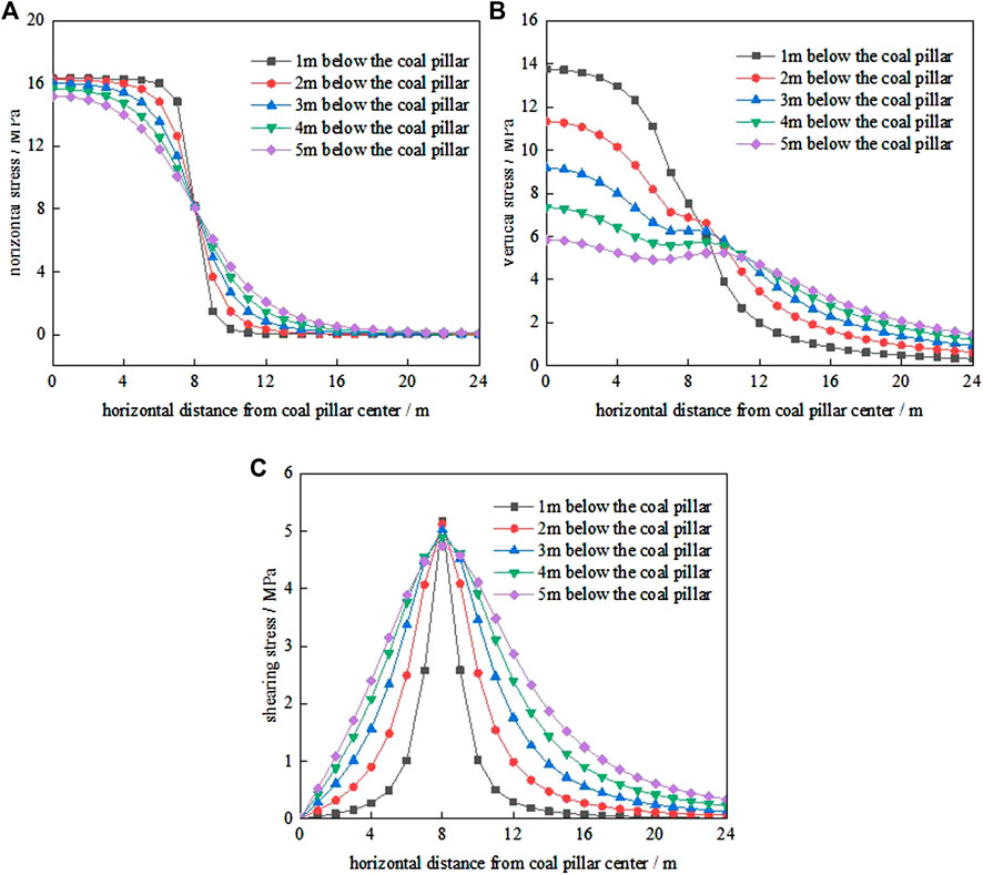
FIGURE 5. Stress distribution curve of the coal pillar floor. (A) distribution of horizontal stress, (B) distribution of vertical stress, (C) distribution of shear stress.
Figure 5A shows:
① The horizontal stress that transmits downward from the coal pillar toward left by the top layer is mainly the compressive stress under the coal pillar (x = 0 ∼ 8 m), showing an apparent stress concentration.
② Near the edge of the coal pillar (x = 8 ∼ 12 m), the horizontal stress decreases rapidly, and its change rate decreases with the increase in depth, which belongs to the transition zone affected by the coal pillar.
③ In the range of x = 12 ∼ 24 m, the horizontal stress tends to be stable and is less affected by the coal pillar.
Similarly, Figure 5B shows:
① The distribution of vertical stress transmitted from the remaining coal pillars to the floor is relatively concentrated, and the constrained high-stress area under the coal pillar (x = 0 ∼ 8 m) decreases with the increase in depth.
② Near the edge of the coal pillar (x = 8 ∼ 14 m), the vertical stress in floor strata fell rapidly, which belonged to the transition zone of the coal pillar influence; ③ In the range of x = 14 ∼ 24 m, the relatively minor vertical stress in the floor strata tends to be stable and less affected by the coal pillar.
Figure 5C shows:
① When the horizontal distance from the center of the coal pillar increases, the shear stress below the coal pillar increases. The shear stress is zero at the center of the coal pillar and reaches the maximum at the edge of the coal pillar.
② Near the edge of the coal pillar and in the range of x = 8 ∼ 16 m, the shear stress decreased with the increase in horizontal distance from the center of the coal pillar was the transition zone affected by the coal pillar.
③ In the range of x = 16 ∼ 24 m, the shear stress was relatively small and tended to be stable.
The previous analysis shows that the lower part of the residual coal pillar (x = 0 ∼ 8 m) was the coal pillar’s concentration area; the horizontal and vertical stresses were higher, and the shear stress gradient was large. The coal pillar edge (x = 8 ∼ 16 m) was the transition zone affected by the coal pillar, and the various gradients of horizontal stress, vertical stress, and shear stress were significant; arranging roadways in these two areas is not conducive to the stability control of the roadway surrounding rock; in the range of x = 16 ∼ 24 m, the horizontal stress, vertical stress, and shear stress were low, the stress gradient was slight and beneficial to the roadway control surrounding rock, and was a reasonable roadway layout range .
Analysis Based on Numerical Simulation
Model Set-Up
Based on mining geological conditions around the 30,117 working face of the Shancheng Coal Industry, FLAC3D (version 6.0) (Itasca, 2019) numerical further understands the stress field characteristics of the residual coal pillar area. The model is shown in Figure 6.
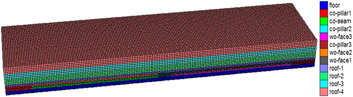
FIGURE 6. Numerical calculation model diagram.
The size of the model was 376 × 100 × 38 m (length × width × height). Horizontal constraints were applied around the model. Horizontal displacement and vertical displacement were constrained at the bottom of the model. We used the vertical load at the model’s top according to the in situ stress of 550 m depth. The failure criterion adopted was the elastoplastic constitutive model, and the failure criterion was the Mohr–Coulomb.
Based on the rock mechanics experiment, we determined a particular reduction coefficient according to different weights to obtain the rock mechanics parameters that were more consistent with the actual field. Table 3 gives each rock stratum’s physical and mechanical parameters in the model. The null element excavates the model, and the excavation sequence is the initial ground stress balance → excavation of the 30105 working face → excavation of the 30104 working face.
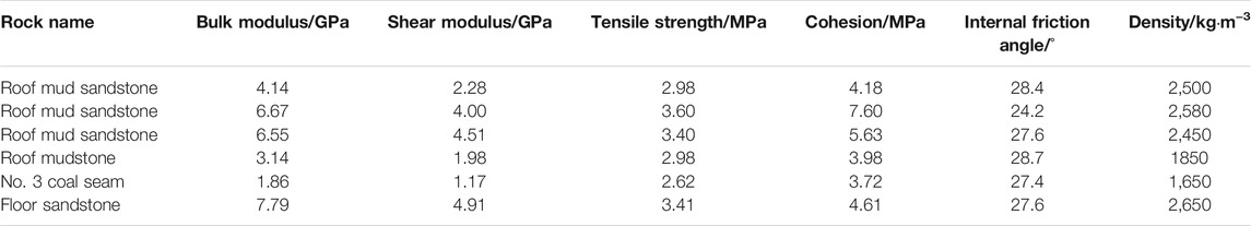
TABLE 3. Physical and mechanical parameters of the coal seam in the model.
Simulation Result Analysis
1) The stress distribution characteristics of 30105 working face after mining
Figure 7 illustrates the vertical stress distribution of the surrounding rock after the end of mining in the 30105 working face. The diagram showed that after mining the 30105 working face, the failure movement of roof strata and the stress redistribution of the surrounding rock occur. As the activity of the mined-out rock tends to be stable, the falling gangue in the mined-out area is gradually compacted and restored the surrounding rock stress in the middle of the working face to the original rock stress. The roof strata near the coal pillar have rotary deformation and tensile failure, and the stress of the surrounding rock transfers to the coal pillar. The stress concentration formed at the coal pillar’s edge near the goaf was transferred to the coal and rock below.
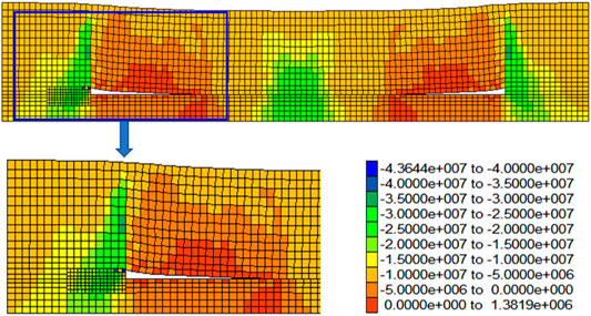
FIGURE 7. 30105 working face after mining vertical stress distribution of surrounding rock.
Figure 8 shows the vertical stress distribution curves of the surrounding rock before and after stopping the 30105 working face. The diagram indicates that after mining 30105 working face, the stress of roof overburden transfers to the section coal pillar and passes down to the lower layered coal and the floor strata through the section coal pillar. Among them, stress concentration on the coal pillar was the highest, and a high-stress concentration area resulted in the range of 2 ∼ 4 m deep into the coal pillar. The stress value exceeds 25 MPa, the maximum is 30.55 MPa, and the stress concentration coefficient is 3.73. The high-stress concentration degree of the lower layered coal was the second, and the high-stress concentration area formed in the range of 3 ∼ 8 m from the edge of the goaf. The stress value exceeds 20 MPa, the maximum is 23.93 MPa, and the stress concentration coefficient is 2.89. The high-stress concentration degree of the floor strata was the lowest, close to 20 MPa in the range of 7 ∼ 11 m from the edge of goaf, the maximum was 19.57 MPa, and the stress concentration factor is 2.36. Finally, we noted that in the stress transfer of the weathered rock, the stress concentration degree shows the characteristics of the upper section coal pillar > lower layer coal > floor rock.
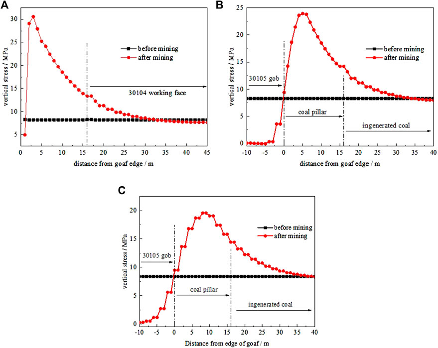
FIGURE 8. Vertical stress distribution of the surrounding rock at different positions before and after mining in 30105 working face. (A) the vertical stress distribution of coal pillar, (B) the vertical stress distribution of lower layered coal, (C) the vertical stress distribution of pavement stratum.
Figures 8B,C show that after the end of the mining of the 30105 working face, the coal and rock under the goaf have a tensile failure, surrounding rock pressure relief, and stress reduction. From the distribution of the stress value, the pressure relief degree of lower layered coal is greater than that of the floor rock. Consequently, the mining influence of lower layered coal is more significant than that of the floor rock.
2) The stress distribution characteristics of the 30104 working face after mining
Figure 9 shows the surrounding rock’s vertical stress distribution after mining in the 30104 working face. The figure shows that the vertical stress distribution of the surrounding rock changes significantly with the mining of the upper layer 30104 working face. With the activity of the upper strata in the middle of the 30104 working face stabilized, the gangue in the goaf was compacted, and the stress of some surrounding rock returned to the original rock stress before mining, and some exceeded the initial rock stress to form stress concentration. The roof strata near the coal pillar edge caused tensile failure due to rotary deformation and reduced the unloading stress of the surrounding rock. However, the coal pillar section bore more rock stress due to the support and thus formed high-stress concentration.
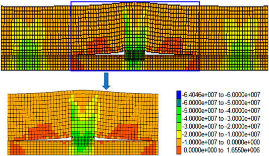
FIGURE 9. Vertical stress distribution of the surrounding rock after mining of 30104 working face.
Figure 10 illustrates the vertical stress distribution curve of the surrounding rock after mining in the 30104 working face. It is seen from Figure 10A that with the mining of the 30104 working face, the vertical stress on the section coal pillar changed significantly: the stress increase in the coal pillar near the edge of the 30104 goaf is the largest, from 13.89 to 43.11 MPa, the stress increase was as high as 29.22 MPa, and the stress concentration coefficient was 3.22. The vertical stress of the edge side of the 30105 goaf near the coal pillar also increased, but it was significantly smaller than that with the increase of the 30104 goaf side. The main reason was that the horizontal distance from the 30104 working face was far, and the influence of mining disturbance was small. We noted that due to the mining influence of the top layer 30104 working face, the stress increase amplitude of the coal pillar on the edge of the 30104 goaf was the largest. The stress increase amplitude of the coal pillar on the edge of the 30105 goaf was the smallest. With the increase in the distance from the mining face, the mining influence degree decreases, and the corresponding stress increase, amplitude decreases.
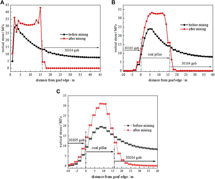
FIGURE 10. Vertical stress distribution of the surrounding rock at different positions before and after mining in 30104 working face. (A) the vertical stress distribution of coal pillar, (B) the vertical stress distribution of lower layered coal, (C) the vertical stress distribution of pavement stratum.
Figures 10B,C show that the vertical stress in the surrounding rock was significantly reduced due to the mining effect of top slicing the 30104 working face. At the same time, due to the increase in vertical stress on the section coal pillar caused by the mining of the 30104 working face, the vertical stress transmitted to the floor coal and rock mass was also increased, and the stress growth change on the coal pillar section was also reflected in the floor coal and rock mass, that is, the stress increase in the floor coal and rock mass near the edge of the 30104 goaf is the largest, and it is attached to the edge of the 30105 goaf.
The complete simulation results show that after mining 30104 and 30105 working faces in the top layer, high-stress concentration is formed on the coal pillar and transferred to the lower layer of coal and floor strata. The stress decreases gradually with the distance from the center of the coal pillar, which is consistent with the law obtained by theoretical calculation. However, due to the mining pressure relief, the surrounding rock stress of the lower layer of coal and floor strata in the goaf decreases.
Analysis of Coal Rock Damage and Failure Law in Residual Pillar Area
According to the slip line field theory (Li, 2004), the failure depth in the floor caused by abutment pressure is evident in Figure 11.
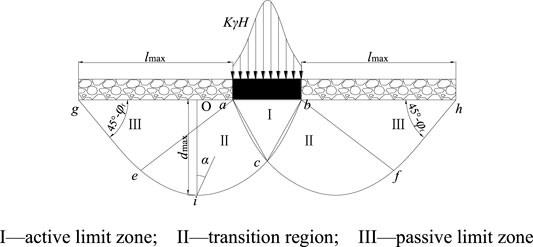
FIGURE 11. Diagram of yield failure of the bottom plate formed by supporting pressure.
I—active limit zone; II—transition region; and III—passive limit zone.
The yield failure depth of floor under slip line field theory is expressed by Eq. 7:
where d is the floor yield failure depth, m; φf is the internal friction angle of floor rock, °; r0 is the area II starting point c to pole distance; and α is the angle between any point axis and starting point axis.
By derivation, the maximum yield failure depth of the floor rock is as follows:
where x0 is the width of the plastic zone of the coal wall, calculated by limit equilibrium theory:
So the maximum failure depth of stope floor calculated by slip line field theory is follows:
Similarly, the maximum horizontal range of floor yield failure under slip line field theory expressing Eq. 13:
where C is the coal cohesion, f is the friction coefficient of the contact surface between the coal seam and the roof and floor, ξ is the triaxial stress coefficient, Pi is the resistance of support to coal rib, and M is the coal seam thickness.
Engineering Practice
To ensure the regular mining replacement of the working face, the Shancheng Coal Industry needs to optimize the location of the return airway of the 30117 working face. The relevant calculation parameters of 30117 working face are in Table 4.
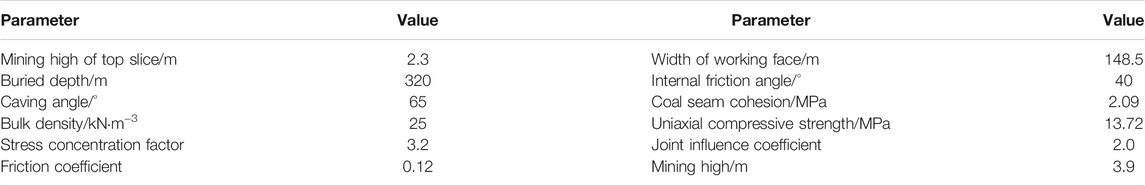
TABLE 4. Relevant calculation parameters of 30117 working face.
According to the theoretical analysis in Analysis Based on Elastoplastic Theory before, the stress concentration area is below the coal pillar of 16 m, and the stress level is high. The stress variation area is within the range of 0–8 m at the edge of the coal pillar, and the stress variation gradient is large. Therefore, the stable stress area is outside 8 m at the edge of the coal pillar. Outside the edge of the coal pillar, 8 m is the stable stress area, the stress level is low, and the stress gradient is slight. Therefore, the return airway of the 30117 working face should be outside 8 m on both sides of the left coal pillar.
From Eqs 12, 13, the plastic failure range of floor based on slip line field theory is:
According to the theoretical calculation results, the coal to be mined in the lower layer 30117 working face is affected by mining the top layer. Therefore, in the range of l × d = 7.95 × 4.45 m on both sides of the coal pillar floor, it will be damaged to varying degrees, and the mechanical properties of the surrounding rock will be weakened, which is not conducive to the control of the surrounding rock of the roadway. Therefore, the roadway layout was outside the above range.
In addition, Figure 1 showed that when the roadway was on the east side of the left coal pillar, the left coal pillar was outside the end area of the working face, which is conducive to the rapid advancement of the working face and the high safety factor. In contrast, when the roadway was on the west side of the left coal pillar, because of the existence of the left coal pillar, the pressure at the end area of the working face was significant, and there was a security risk.
Based on the earlier analysis results, the layout position of the return airway in the 30117 working face is determined to be 8 m away from the east side of the left coal pillar. In addition, field practice shows that the roadway surrounding rock control effect is favorable.
Conclusion
1) Based on the collapse of the mined-out area, we constructed the coal pillar and mined-out area’s load calculation model and the load set calculation method was obtained.
2) The mechanical model of residual pillar load propagation in the floor is established, and the analytical formula of floor stress is derived. We concluded that the stress field in the residual coal pillar area presents the characteristics of the non-uniform distribution. The stress concentration area appears below the coal pillar, the stress variation area appears at the edge of the coal pillar, and the stress stability area appears in the distance. The stress level below the coal pillar is high, and the stress gradient at the edge of the coal pillar is large, which is not conducive to the layout of the roadway. On the other hand, the stress level away from the coal pillar area is low, and the stress change gradient is slight, which is a proper roadway layout position.
3) FLAC3D was used to simulate the stress distribution of the coal pillar area before and after mining the top-stratified working face. After mining the top-stratified working face, the results showed that a high-stress concentration was formed on the coal pillar and transmitted to the lower stratified abutment area and the floor rock layer. In contrast, the lower stratified abutment area and the floor rock layer in the goaf is due to mining pressure relief, the stress of the surrounding rock was reduced, and the degree of stress concentration was characterized by the section coal pillar > lower stratified abutment area > floor rock layer.
4) Based on the slip line field theory, the yield failure model of the floor is established. The expressions of yield failure depth of floor were obtained and the damage range of coal and rock mass, on both sides of coal pillar floor affected by the mining of top slice working face was defined.
5) Based on the research results of the stress field distribution characteristics and the failure law of coal and rock in the residual coal pillar area, the excellent layout area of the roadway was determined to be 8 m away from the two sides of the coal pillar, avoiding the influence of stress concentration, facilitated the rapid advancement of the working face, and solved the problem that the residual coal pillar was located in the end area of the working face, which caused the hydraulic support to be stressed.
Data Availability Statement
The raw data supporting the conclusion of this article will be made available by the authors, without undue reservation.
Author Contributions
Conception and design of study: FW, XY, and GZ; Acquisition of data: BD, BL, JZ, and GZ; Analysis and/or interpretation of data: FW, XY, and BD; Drafting the manuscript: XY, BL, and JZ; Revising the manuscript critically for important intellectual content: FW, XY, and GZ; Article polishing: GZ and XY.
Funding
The work was supported by the National Natural Science Foundation of China (52174138).
Conflict of Interest
GZ was employed by the company Shanxi Yangcheng Shancheng Coal Industry Co., Ltd.
The remaining authors declare that the research was conducted in the absence of any commercial or financial relationships that could be construed as a potential conflict of interest.
Publisher’s Note
All claims expressed in this article are solely those of the authors and do not necessarily represent those of their affiliated organizations, or those of the publisher, the editors, and the reviewers. Any product that may be evaluated in this article, or claim that may be made by its manufacturer, is not guaranteed or endorsed by the publisher.
Acknowledgments
The authors gratefully acknowledge the financial support of the agencies aforementioned.
References
Bai, Q.-S., Tu, S.-H., Wang, F.-T., Zhang, X.-G., Tu, H.-S., and Yuan, Y. (2014). Observation and Numerical Analysis of the Scope of Fractured Zones Around Gateroads under Longwall Influence. Rock Mech. Rock Eng. 47 (5), 1939–1950. doi:10.1007/s00603-013-0457-9
Bai, Q., Tu, S., Wang, F., and Zhang, C. (2017). Field and Numerical Investigations of Gateroad System Failure Induced by Hard Roofs in a Longwall Top Coal Caving Face. Int. J. Coal Geology. 173, 176–199. doi:10.1016/j.coal.2017.02.015
Dai, H., Guo, J., Yi, S., Wang, G., Liu, A., Kong, B., et al. (2013). The Mechanism of Strata and Surface Movements Induced by Extra-thick Steeply Inclined Coal Seam Applied Horizontal Slice Mining. J. China Coal Soc. 38 (07), 1109–1115. doi:10.13225/j.cnki.jccs.2013.07.017
Huang, Q., Cao, J., and Du, J. (2019). Research on Three-Field Evolution and Rational Coal Pillar Staggered Distance in Shallow Buried Closely Spaced Multi-Seam Mining. J. China Coal Soc. 44 (03), 681–689. doi:10.13225/j.cnki.jccs.2018.6035
Huang, Q., Cao, J., and Gao, B. (2020). Damage-Reducing Mining Based on Three Fields Evolution in Shallow Buried Closely Spaced Multi-Seam. J. Mining Saf. Eng. 37 (06), 1171–1179. doi:10.13545/j.cnki.jmse.2020.06.011
Huang, Q., Du, J., Chen, J., and He, Y. (2021). Coupling Control on Pillar Stress Concentration and Surface Cracks in Shallow Multi-Seam Mining. Int. J. Mining Sci. Tech. 31 (01), 95–101. doi:10.1016/j.ijmst.2020.12.019
Itasca (2019). User's Manuals of FLAC3D: Fast Lagrangian Analysis of Continua in 3D. version 4. Minneapolis, MN: Itasca Consulting Group Inc.
Liu, X., Li, X., and Pan, W. (2016). Analysis on the Floor Stress Distribution and Roadway Position in the Close Distance Coal Seams. Arabian J. Geosciences 9 (2), 83.
Mu, H., Bao, Y., Song, D., and Su, D. (2021). Investigation of Strong Strata Behaviors in the Close-Distance Multiseam Coal Pillar Mining. Shock and Vibration 2021, 1–14. doi:10.1155/2021/1263275
Shen, W., Bai, J., Zhao, Z., Shen, X., Wang, X., and Kang, J. (2018). Three Indexes Method for Roadway Layout below the Closed Residual Bearing Coal Pillar. J. Mining Saf. Eng. (03), 465–472.
Tian, C., Yang, X., Sun, H., Liu, Y., and Hu, Q. (2019). Experimental Study on the Overburden Movement and Stress Evolution in Multi-Seam Mining with Residual Pillars. Energ. Sci. Eng. 7 (6), 3095–3110. doi:10.1002/ese3.482
Wang, J. (2009). Theory and Technology of Thick Coal Seam Mining. Beijing: Metallurgical Industry Press. doi:10.3969/j.issn.2095-2783.2008.11.007
Wang, J., and Zhong, S. (2008). The Present Status and the Key Issues to Be Resolved of Thick Seam Mining Technique in China. Sci. paper Online 3 (11), 829–834.
Yue, X., Tu, M., and Li, Y. (2021). Calculation of Subsidiary Mining Stress in Floor Roadway under the Remaining Boundary Pillar of Close Coal Seam Mining. J. Mining Saf. Eng. 38 (02), 246–252+259. doi:10.13545/j.cnki.jmse.2019.0501
Zhang, B. (2001). High-Productive & High-Efficient Technologies of China's Coalmines. Xuzhou: China University of Mining and Technology Press.
Zhao, H., Cheng, H., and Ji, D. (2021b). Study of the Mechanism and Evolution Law of Unsymmetrical Failure of the Mining Roadway in Close Distance Coal Seam. J. China Univ. Mining Tech. 50 (06), 1029–1040+1050. doi:10.13247/j.cnki.jcumt.001342
Zhao, H., Cheng, H., and Li, J. (2020). Study on Asymmetric Deformation Mechanism of Surrounding Rock of Roadway under the Effect of Isolated Coal Pillar. Chin. J. Rock Mech. Eng. 39 (S1), 2771–2784. doi:10.13722/j.cnki.jrme.2019.0934
Keywords: slice mining, residual pillar, stress distribution, floor failure depth, numerical simulation
Citation: Wu F, Yu X, Zhao G, Du B, Lv B and Zhang J (2022) Characteristics of Stress Field and Damage Law of Coal Rock in Residual Pillar of Top Slice and Its Application. Front. Earth Sci. 10:835531. doi: 10.3389/feart.2022.835531
Received: 14 December 2021; Accepted: 19 January 2022;
Published: 18 February 2022.
Edited by:
Qingsheng Bai, Freiberg University of Mining and Technology, GermanyReviewed by:
Zhenlei Li, University of Science and Technology Beijing, ChinaBaobao Chen, Anhui University of Science and Technology, China
Copyright © 2022 Wu, Yu, Zhao, Du, Lv and Zhang. This is an open-access article distributed under the terms of the Creative Commons Attribution License (CC BY). The use, distribution or reproduction in other forums is permitted, provided the original author(s) and the copyright owner(s) are credited and that the original publication in this journal is cited, in accordance with accepted academic practice. No use, distribution or reproduction is permitted which does not comply with these terms.
*Correspondence: Xin Yu, TS20020070A31LD@cumt.edu.cn