Deformation and Failure Characteristics of Loading and Unloading Rock Based on Volume Crack Strain
 Xiaohui Liu
 Yu Zheng
 Jinyun Guo5
  Yang Xue
- 1Key Laboratory of Fluid and Power Machinery, Ministry of Education, Xihua University, Chengdu, China
- 2Key Laboratory of Deep Earth Science and Engineering, Ministry of Education, Sichuan University, Chengdu, China
- 3School of Energy and Power Engineering, Xihua University, Chengdu, China
- 4Southwest Municipal Engineering Design & Research Institute of China, Chengdu, China
- 5Research Center for Social Development and Social Risk Control of Sichuan Province, Key Research Base of Philosophy and Social Science, Sichuan University, Chengdu, China
In order to study the laws of crack evolution in rock and explain its fracture instability mechanism, a series of laboratory tests were carried out with Jinping Marbles. The test results show that the failure degree of marbles under unloading conditions is more severe than that under loading conditions. Based on volume crack strain, five progressive failure stages of crack evolution under different conditions are divided, and the corresponding characteristic stresses are determined. The pre-peak volume crack propagation strain without considering the initial damage is used to evaluate the pre-peak crack growth propagation degree of rock, and it is found that the lower the confining pressure, the higher the strain rate and unloading rate, the less the cracks generated before the peak, and the more the rock is prone to brittle failure after the peak. The starting point of the sharp increase of volume crack strain rate is proposed as the failure precursor point, and stress levels of failure precursor of marbles are in 70%–100%, which decrease as confining pressure, strain rate, and unloading rate rise. Under unloading conditions, failure precursor points appear later and are close to the unloading point, and unloading rocks are more prone to sudden brittle failure.
1 Introduction
There are many defects in rock, such as joints, cracks, and pores in natural rock materials due to complex geological tectonic movement. These inherent discontinuities seriously weaken the mechanical properties and the stability of the internal structure of rock (Li et al., 2018; Li et al., 2020; Yan et al., 2021). Especially under the condition of high ground stress, a large amount of energy is accumulated in deep rock mass, and the energy stored in rock mass is rapidly released under the action of excavation and unloading, causing dynamic disasters such as rock burst and impact instability, which brings great challenges to the safety of construction workers and equipment (Cai and Kaiser, 2005; Zhou et al., 2015; Dong et al., 2020; Feng et al., 2022). Therefore, this study investigates the deformation and failure mechanisms of rock under different excavation disturbance conditions, and predicts the failure precursors of rock, which is of great significance to the stability of surrounding rock and early warning of rock dynamic disasters.
Deformation and failure of rock are the result of internal micro-cracks evolution, which leads to the deterioration of rock mechanical properties and the instability of its internal structure. In order to interpret crack evolution laws of rocks under different conditions, scholars usually analyze from macroscopic and microscopic aspects. From the perspective of macroscopic mechanical properties, deformation and failure characteristics of rock can be reflected by stress-strain curve, strength deformation parameters, and macroscopic damage characteristics. From the microscopic point of view, the acoustic emission method can be used to monitor the engineering rock mass in real-time, and directly judge the structure of abnormal areas in rock mass to predict the occurrence of dynamic disasters (Dong et al., 2021a). However, in laboratory tests, the root cause of rock instability and failure can be better explored based on the non-linear evolution law of micro-cracks inside rock (Chen et al., 2016; Jin et al., 2017; Zuo et al., 2017; Chen and Guo, 2020). Based on lots of rock mechanics tests, Bieniawski analyzed rock fracture characteristics using fracture mechanics theory, and found that the crack evolution process can be divided into stable and unstable stages (Bieniawski, 1967). To clarify the deformation and failure stages of rock, Martin firstly proposed to use the crack strain variable to analyze (Martin, 1993). Through compression tests of granites, Martin and Chandler further expounded the progressive failure process and fracture mechanism of rock in detail (Martin and Chandler, 1994). On this basis, Cai et al. (2004) found that characteristic stress thresholds can be obtained according to evolution characteristics of crack strain, which is still an important method to determine characteristic stresses of rock. In addition, to ensure the safety and stability of the project, it is necessary to identify rock failure precursors and predict rock failure. From a macro perspective, the turning point where tensile cracks extend and merge with shear cracks can be regarded as a failure precursor point, but it is difficult to be captured in laboratory tests (Hoek and Martin, 2014). From a micro perspective, rock failure precursor also can be determined by Acoustic emission (AE) (Yu et al., 2022), infrared thermography, and other auxiliary monitoring methods. Dong et al. (2021b, 2021c) predicted the precursors of rock instability and failure based on the unstable evolution trend of the AE event rate in the plastic stage. However, there are still some limitations, such as failure precursors with infrared thermography that usually appear later and are not prioritised in time, and that AE is greatly influenced by lithology, loading and unloading conditions, and is difficult to satisfy the conditions for determining failure precursors (Cong et al., 2016; Chen et al., 2021). Since instability of the rock medium was directly caused by microcrack propagation, crack propagation velocity variation reflects the change of rock damage degree. Based on this, how to propose a more accurate and universal prediction method of rock failure precursor is worth in-depth consideration. Considering different excavation disturbance conditions, to determine more accurate failure precursor based on evolution law of volume crack strain rate, is significant to earlier warning and prevention of rock dynamic disaster and ensure the long-term stability of surrounding rock.
However, the crack propagation characteristics of rock are different when under different stress states. Zuo et al. (2019) studied the crack evolution laws of rock during the progressive failure process under the influence of confining pressure, and pointed out that confining pressure can restrain crack propagation in rock (Chen et al., 2020). Xing et al. (2018) found that the stress level of crack initiation is higher under quasi-static strain rate than that under dynamic strain rate, indicating that rock fracture is more rapid in dynamic conditions. At present, relevant studies based on conventional loading tests have obtained abundant achievements, but there are few reports on the crack evolution laws of unloading rock. Before the excavation of underground geotechnical engineering, rock is in a three-dimensional pressure state, and conventional compression tests are sufficient to study the general mechanical behavior of rock. While in actual projects (such as underground chamber and tunnel excavation), rock mass is disturbed differently with different excavation rates, which affects rock cracking behavior to some extent (Zhou et al., 2018; Zhao et al., 2019), and the non-linear mechanical properties of rock cannot be fully interpreted through conventional loading tests at this time. Therefore, considering confining pressure, strain rate, and unloading rate conditions, loading and unloading rock mechanical tests were carried out to study the crack evolution law of rocks under different conditions to obtain progressive failure characteristics and predict failure precursor, which is beneficial to explain rock deformation mechanism under complex stress, and to provide technical support for design, construction, and risk control of underground tunnel and surrounding rock.
2 Loading and Unloading Tests of Marble
2.1 Test Specimen and Equipment
Rock samples in the tests are marbles taken from Jinping II hydropower station, with a burial depth of +2400m. According to the recommended standard of the International Society for Rock Mechanics, i.e., ISRM (Ulusay, 2014), rock cores were cut and polished into standard cylindrical samples, with a diameter of 50 mm and a height of 100 mm, some of the marble samples can be seen in Figure 1A. It is requested that the diameter should be controlled at
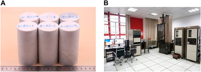
FIGURE 1. Test specimen and equipment: (A) Marble specimens; (B) MTS815 rock mechanics test system.
Both loading and unloading tests were carried out on the MTS815 Flex Test GT rock mechanics test system of the Key Laboratory of Deep Earth Science and Engineering Ministry of Education of Sichuan University, which was shown in Figure 1B, and the MTS test system is mainly composed of power system, hydraulic power system, servo threshold system, and host system. This system can be used to carry out uniaxial tests and triaxial loading and unloading tests under dynamic or static conditions, and it is loaded by stress or strain control.
2.2 Discrete Analysis
Affected by the geological tectonic movement, there exist some primary defects inside marble, which means that the rock samples taken from the same environment have a certain discreteness. In order to reduce the influence of rock sample discreteness on test results, rock samples with similar physical parameters, such as density and p-wave velocity, were selected and tested in the same group. The higher the density and p-wave velocity, the denser the internal structure of rock, and the stronger its mechanical strength, and the two parameters can indirectly reflect differences in rock internal structure. The dispersion degree of rock samples can be analyzed by dispersion indexes, such as mean value, standard deviation, and variation coefficient, and the analysis results were listed in Table 1. It can be seen from the table that the standard deviation of ρ, ρ/ρmax, Vp/Vp max under loading and unloading tests is much less than 1, and their variation coefficient is within 10%, which indicates that the dispersion degree of rock samples meets the requirements of the test specification.

TABLE 1. Discrete analysis of marble samples.
2.3 Test Plan
In order to study crack evolution law in rock under different excavation conditions and explain its deformation and failure mechanism, taking Jinping marble as an example to carry out indoor tests under different loading and unloading conditions. In this paper, quasi-static triaxial compression test, constant confining pressure loading test, and unloading test under different initial confining pressure and unloading rate were designed, and there are three rock samples in each group of parallel tests. The detailed test plans were listed in Table 2.
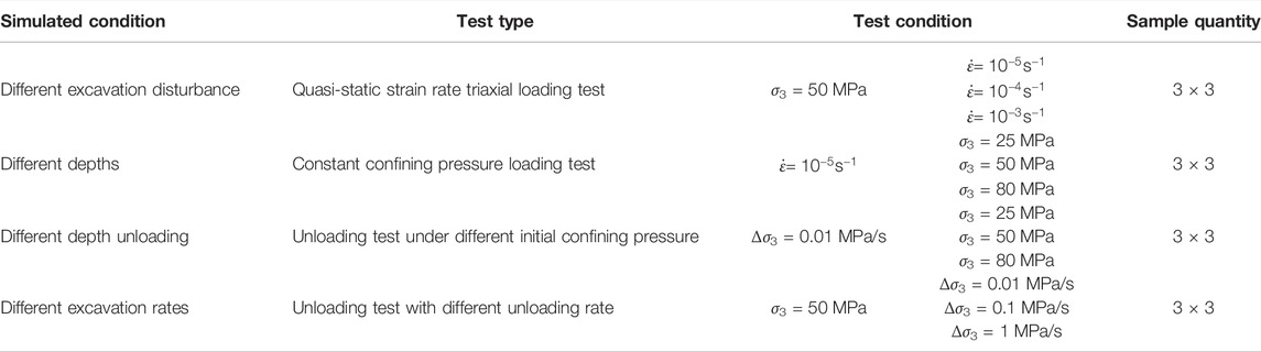
TABLE 2. Test plan.
The stress path diagram of the triaxial loading and unloading test was shown in Figure 2, and the detailed test methods are as follows:
(1) In the quasi-static loading test, first respectively load confining pressure and axial pressure to 50 MPa at 0.06 mm/min and 3 MPa/min loading rate, and then continue to load axial pressure at 10−5s−1, 10−4s−1, and 10−3s−1 strain rates respectively by strain control. In this test, strain control loading is realized by the Linear Variable Differential Transformer, i.e., LVDT, and the loading rates corresponding to 10−5s−1, 10−4s−1, and 10−3s−1 strain rate are 0.06 mm/min, 0.6 mm/min, and 6 mm/min respectively.
(2) In the constant confining pressure loading test, the strain rate maintains at 10−5s−1, and the application of confining pressure is controlled by stress. The test procedure of the constant confining pressure loading test is consistent with the quasi-static loading test, but in the initial stage, confining pressure is respectively imposed to 25, 50, and 80 MPa at 3 MPa/min loading rate.
(3) In the triaxial unloading test, after being loaded to hydrostatic pressure state, continue loading to preset axial pressure at 0.06 mm/min loading rate, then start to unload the confining pressure until rock sample damages, and the stress level at the unloading point is 80% of the triaxial compressive strength in this test. In the unloading test, when considering the influence of initial confining pressure, unload at 0.01 MPa/s unloading rate under conditions of 25, 50, and 80 MPa confining pressure respectively; While considering the influence of unloading rate, the initial confining pressure is 50 MPa, then unload at 0.01, 0.1, and 1 MPa/s unloading rate respectively.
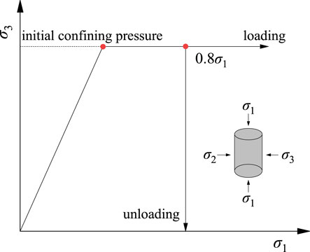
FIGURE 2. Stress path of loading and unloading tests.
3 Analysis of Test Results
3.1 Stress-Strain Curve
Stress-strain curves of marbles under different loading and unloading conditions were plotted in Figure 3, they all show a trend of changing from linear growth to non-linear growth. Taking the marble sample under 25 MPa confining pressure as an example, the stress-strain curves of marbles can be simply divided into four stages, that is linear stage A, non-linear stage B, stress plateau stage C, and post-peak failure stage D. It can be seen that in the linear stage before the peak, stress-strain curves are basically consistent under different conditions, and rock is in an elastic state with little difference in elastic modulus at this stage. As stress increases further, the rock enters the plastic stage, and the strain increases faster than stress. Meanwhile, the external input energy is mainly used for the micro crack evolution, and the micro-cracks begin to expand and extend rapidly, leading to the plastic deformation of marble. With initial confining pressure rising, the plastic characteristics of marble enhance, but strain rate and unloading rate have no significant effect on it. At peak stress, there is no immediate stress drop under confining pressure conditions, but there is a stress flat, where the stress distribution inside the rock reaches a steady state.
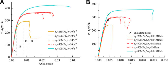
FIGURE 3. Deviatoric stress-axial strain curves of marble samples: (A) loading condition; (B) unloading condition.
In the post-peak failure stage, stress drop occurs but the stress drop degree in the unloading state is obviously higher than the loading state, showing that unloading marble is more prone to severe brittle failure. With an increase of initial confining pressure, the stress drop rate gradually decreases, and the failure of marble transitions from brittle to plastic. Under 80 MPa confining pressure, there is even no obvious stress drop, and the rock shows an approximately ideal plastic state. The influence of strain rate and unloading rate on the stress-strain curve is more obvious in post-peak. As strain rate and unloading rate increase, stress drop rate increases slightly, and brittle failure characteristics of marble enhance. It can be seen that marbles have different mechanical responses under the action of confining pressure, strain rate, and unloading rate, and the effect of confining pressure on mechanical behavior is more significant.
Under the quasi-static strain rate, the peak stress of triaxial marble fluctuates around 350 MPa. For loading and unloading tests under different confining pressures, the peak stress under both stress paths increases with the increase of confining pressure, but the peak stress of unloaded marble is lower than that of loading under the same initial confining pressure, which indicates that unloading weakens rock ability to resist deformation and failure. When unloading under the initial confining pressure of 50 MPa, the peak stress increases slightly as the unloading rate increases. In the loading and unloading test, linear stages of stress-strain curves under different strain rates and unloading rates basically coincide, and the elastic modulus of marble has little difference. With confining pressure increasing, the slope of the linear phase of the stress-strain curve gradually increases, and the elastic modulus of marble also increases. The larger the elastic modulus, the stronger the rock stiffness and the ability to resist deformation and damage, which also shows that confining pressure can restrain rock deformation.
3.2 Macroscopic Failure Characteristics
Macroscopic failure modes of marbles under loading and unloading were seen in Figure 4, the red line in the figure represents the main crack and the blue line represents the secondary crack. As shown in Figure 4A, rock sample under 25 MPa confining pressure occurs double-shear failure, and tensile fissures highly develop between two parallel main shear cracks. At 50 MPa confining pressure, the sample shows single-shear failure, and there are few secondary shear cracks around the main shear crack. At 80 MPa confining pressure, microcracks fully developed under the action of axial stress, main shear crack without penetration, and dilatancy appears. As confining pressure rises, variation of failure modes of marble specimens shows that confining pressure limits the circumferential deformation of rock. As shown in Figure 4B, the sample under 10−4s−1 strain rate occurs shear failure in “V” shape, and secondary shear cracks are distributed near the main cracks. At 10−3s−1 strain rate, two parallel shear cracks penetrate surface the rock surface, and secondary cracks are distributed between them. As the strain rate increases, marble specimens change from single-shear failure to double-shear failure, and the failure degree gradually intensifies.
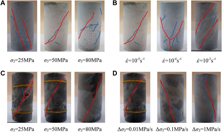
FIGURE 4. Macroscopic failure modes of marble samples: (A) constant confining pressure condition
Under unloading conditions, as shown in Figure 4C, under 25 MPa initial confining pressure, a shear zone with large width is formed on the rock surface, and there are many fragments distributed in the zone, which is caused by friction and extrusion between fracture surfaces. Under 50 MPa initial confining pressure, the shear zone gets narrowed, and at higher confining pressure only one thin shear crack penetrates the rock surface. Therefore, with the increase of initial confining pressure, unloading marbles transition from tensile-shear composite failure to shear failure. As shown in Figure 4D, under 0.1 MPa/s unloading rate, a shear zone with small width penetrates the rock sample, and secondary cracks appear near it. Under 1 MPa/s unloading rate, the sample undergoes tensile shear failure, the fracture surface is steep, and shows brittle failure is obvious. Therefore, as the unloading rate increases, marble failure modes transition from shear failure to tensile shear failure. Compared with the loading path, the macroscopic failure degree of marble under unloading condition is more serious, and micro-cracks develop more fully, which is unfavorable for engineering.
3.3 Progressive Failure Process Based on Crack Strain
As is known, micro-crack evolution is a direct cause of rock failure. As shown in Figure 5, rock instability and failure are mainly caused by microcrack closure, initiation, expansion, and coalescence, which is a progressive failure process. As can be seen from Section 3.1, the stress-strain curve of marble tends to change in stages, but each stage cannot be defined accurately from the curve, which has certain subjectivity. In order to study the deformation and failure mechanism of rock during progressive failure stages, and quantitatively analyze crack evolution law in rock during the loading and unloading process, the crack strain variable can be used to describe crack propagation characteristics in rock. Crack strain refers to the axial and circumferential deformation caused by initiation, propagation, and coalescence of original cracks and initiation of new cracks under the action of external loads (Martin, 1993). Its physical significance is the difference between the true strain and elastic strain of rock under small deformation conditions. In this paper, in order to directly reflect the amount of rock deformation, volume crack strain was used to reflect the deformation caused by both axial and circumferential crack propagation. Based on this, the calculation method of volume crack strain can be described as:
where,

FIGURE 5. General progressive failure process of rock.
According to Hooke’s law,
where,
Therefore, crack strain can be calculated as (Zuo et al., 2019):
According to Eq. 4, the volume crack strain of rock samples under different stress conditions can be calculated, and then taking the volume crack strain and volume strain as the main analysis variables. Through the evolution characteristics of deviatoric stress-axial strain, volume strain-axial strain, and volume crack strain-axial strain curves of marble (seen in Figure 6), its progressive failure process under loading and unloading conditions can be divided into five stages. In the crack closure stage (Stage I), volume crack strain first increases in a positive direction and then tends to be stable, this is because original fissures in rock gradually closure under external loads. When primary cracks reach a completely closuring state, volume crack strain is close to 0, and the corresponding stress at point A is the closure stress σcc. In the linear elastic stage (Stage II), the volume crack strain is almost constant, indicating that the rock sample is in a linear elastic state. If unloading at this stage, the sample can be restored to its original state. In the crack stable growth stage (stage III), volume crack strain increases in a negative direction as loading continues, and the corresponding stress at the initial increasing point (point B) is the initiation stress σci. At this time, original cracks gradually propagate and tension cracks initiate, causing irreversible damage to the rock. In the crack rapid growth stage (stage IV), volume strain gradually decreases from the positive maximum value, showing that the rock sample turns from compression to expansion, and the stress at the maximum point C of volume strain is the damage stress σcd. And during this process, tension cracks rapidly expand and then conflate to form shear cracks, which leads to macrocracks appearing in the specimen surface. In the post-peak failure stage (Stage V), after peak stress (point D), macrocracks penetrate the rock sample, dislocation slip occurs at the fracture surface, and the rock sample eventually fractures.
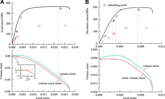
FIGURE 6. Progressive failure process of marble samples: (A) loading condition [
Different stages of crack evolution correspond to different stress levels, and characteristic stress is an important index to characterize the progressive failure process of rock, it can be defined as the closure stress σcc, initiation stress σci, and damage stress σcd. Meanwhile, characteristic stress is also an important index to evaluate the damage degree of rock mass caused by excavation disturbance in engineering rock mass excavation, which is significant to the design and long-term stability of geotechnical engineering (Martin and Chandler, 1994). As mentioned above, taking volume crack strain and volume strain as analysis variables, the progressive failure process of marble is divided and the corresponding characteristic stress thresholds are determined. Since unloading conditions only weaken rock peak stress, the influence of strain rate and confining pressure on characteristic stresses of marble was discussed in this paper. As shown in Figure 7, in order to eliminate the effect of differences in marble samples on characteristic stresses, they were normalized to be analyzed. It can be found from Figure 7A that as the strain rate rises from 10−5s−1 to 10−3s−1, stress levels of σcc, σci, and σcd respectively increase from 0.135,0.341, and 0.690 to 0.295,0.551, and 0.727. With confining pressure increasing from 25 to 80 MPa, stress levels of σcc and σcd respectively increase from 0.158 and 0.693 to 0.162 and 0.710, and σci first decrease from 0.418 to 0.341 and then increase to 0.396. In general, the higher the strain rate and confining pressure, the higher the stress level of characteristic stress, this is because the increase in confining pressure and strain rate enhances rock bearing capacity, and crack propagation in rock needs to reach a higher stress level.
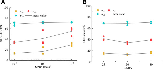
FIGURE 7. Characteristic stress thresholds of marbles: (A) strain rate condition; (B) confining pressure condition.
3.4 Progressive Evolution Law of Deformation Parameters
To interpret progressive failure mechanisms of marble under loading and unloading conditions, the deformation modulus E and generalized Poisson’s ratio μ were introduced to further analyze. Deformation modulus refers to the ratio of stress increment to strain increment, and Poisson’s ratio is the ratio of lateral strain to axial strain. The calculation method of deformation modulus and Poisson’s ratio under triaxial conditions is as follows (Zhu et al., 2020):
Deformation modulus and Poisson ratio of marbles under loading and unloading tests were calculated by Eqs. 5, 6, and evolution curves of deformation parameters under two conditions were respectively plotted in Figures 8, 9. In the loading state, as shown in Figure 8A, with confining pressure rising from 25 to 80 MPa, initial deformation modulus increases from about 81 to 90 GPa, but strain rate has no obvious effect on initial deformation modulus of marble. After reaching damage stress, deformation modulus all show a continuously declining trend, and its decreasing rate becomes faster when stress is closer to the peak value, which is due to the continuous increase of plastic deformation caused by rapid propagation of internal cracks in marble. During this period, the lower the confining pressure and the higher the strain rate, the faster the decreasing rate of deformation modulus, indicating that amount of rock deformation is larger under low confining pressure and high strain rate. After peak stress, rock fracture leads its bearing capacity to weaken and deformation modulus to decrease, and the decreasing rate is obviously lower than that of the pre-peak stage. As shown in Figure 8B, the Poisson ratio before the damage stress is basically stable which can be considered as an elastic constant, since marble is approximately in an elastic state and only generates little circumferential deformation at this time. After damage stress, circumferential deformation increases rapidly due to crack propagation and conflation, and the Poisson ratio correspondingly increases to more than 0.5. At this time, Poisson’s ratio includes both volume deformation and crack propagation deformation, so it is called generalized Poisson’s ratio and cannot be regarded as an elastic constant (Martino and Chandler, 2004; Xing et al., 2018). With the increase of confining pressure, the increasing rate of Poisson’s ratio decreases gradually, and the Poisson’s ratio at peak stress also decreases, but its variation trend under different strain rates is almost similar. After peak stress, the increasing rate of Poisson’s ratio slows down and then gradually stabilizes.
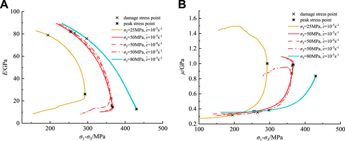
FIGURE 8. Deformation parameters under loading conditions: (A) deformation modulus; (B) Poisson’s ratio.
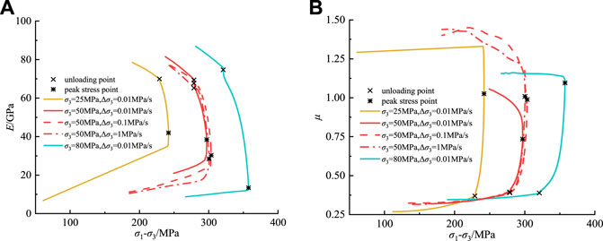
FIGURE 9. Deformation parameters under unloading conditions: (A) deformation modulus; (B) Poisson’s ratio.
In the unloading state, as shown in Figure 9A, With initial confining pressure rising from 25 to 80 MPa, the initial deformation modulus increases from about 79 to 89 GPa. After the unloading point, the deformation modulus drops suddenly, since unloading the confining pressure makes the tension cracks fully propagate, axial deformation greatly increases, and decreasing rate of deformation modulus is faster than that of the loading state. With an increase of initial confining pressure and unloading rate, the decreasing rate of deformation modulus in this stage decreases slightly. When peak stress is reached, the deformation modulus decreases slowly. As shown in Figure 9B, the Poisson ratio can also be regarded as an elastic constant before the unloading point, but after the unloading point due to the decrease of confining pressure, a large amount of circumferential deformation rapidly occurs resulting in a sharp increase in Poisson’s ratio, and its increasing rate is significantly higher than that of loading state. Under unloading conditions, the Poisson ratio at peak stress point is almost greater than 1, which indicates that unloading marbles generate more deformation amount. With initial confining pressure increasing and unloading rate decreasing, the increasing rate of Poisson’s ratio decreases slightly. After peak stress, the Poisson ratio continues to increase due to the complete failure of the rock.
4 Discussion
4.1 Characteristic Volume Crack Strain
Typical deviatoric stress-crack volumetric strain curves of marble was plotted in Figure 10, from which its crack propagation characteristic can be analyzed. Under the action of external loads, as deviator stress increases volume crack strain shows a trend of first increasing, then remaining constant, and finally decreasing. The larger the volume crack strain, the smaller its absolute value, reversely, the smaller the volume crack strain, the larger its absolute value, which indicates that more microcracks are generated in the rock.

FIGURE 10. Typical deviatoric stress-crack volumetric strain curves of marble.
Defining the variable quantity of volume crack strain in the crack closure stage as the initial volume crack closure strain
The pre-peak volume crack propagation strain without considering initial damage under different loading and unloading conditions was shown in Figure 11. In the loading state, as the strain rate rises from 10−5s−1 to 10−3s−1, the mean value of
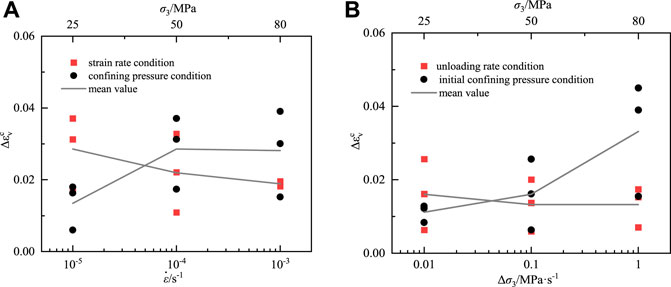
FIGURE 11. Volume crack propagation characteristic of marble samples: (A) loading condition; (B) unloading condition.
4.2 Evolution Characteristics of Volume Crack Strain Rate
Under the action of external loads, crack propagation velocity plays a decisive role in failure process of rock (Alneasan et al., 2019). In laboratory tests, it is difficult to directly and effectively obtain the crack propagation velocity of rock. Since the variation rate of volume crack strain in each progressive failure stage is obviously different, it also can reflect crack propagation degree in rock in different failure stages. In this paper, volume crack strain rate, which is the derivative of volume crack strain to time, was introduced to quantitatively analyze the progressive failure process of marble, and its calculation method is as follows.
where t is the loading and unloading time, s;
Volume crack strain rate of marble under different loading and unloading conditions was shown in Figure 12. Marble samples with 10−5s−1 strain rate and 0.01 Mpa/s unloading rate under the initial confining pressure of 50 MPa were respectively taken as examples. Due to the discreteness of test data, the calculated volume crack strain rate fluctuates, a smooth volume crack strain rate curve can be obtained by the moving average method. It can be seen from Figure 12A that the volume crack strain rate curve of marble increases non-linearly with axial strain increasing. In the crack closure stage and linear elastic stage, the volume crack strain rate is relatively low, and the rock is almost in a stable state. After entering the crack stable growth stage, the volume crack strain rate increases slowly, but its growth rate increases at the crack rapid growth stage. In the peak stress flat stage, the growth rate of volume crack strain rate first slows down as marble reaches a new stable state, and then suddenly increases in post-peak. As shown in Figure 12B, in the unloading state, the variation trend of volume crack strain rate before the unloading point is similar to that under loading conditions. It can be found that the volume crack strain rate drops suddenly at the unloading point and then continues to rise until rock failure, the reason why is that there was a brief pause in the test caused by the change from axial compression to confining pressure unloading at unloading point. After the unloading point, although confining pressure continues to decrease, the deviator stress still increases slowly under the condition of constant axial pressure, and after the short stress re-adjustment, lateral restraint on the rock is gradually weakened due to the influence of unloading confining pressure. Meanwhile, microcracks extend rapidly and the crack strain rate sharply increases accordingly, so the steady increase state of crack strain rate in this stage does not occur in the unloading state.
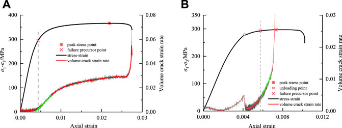
FIGURE 12. Crack strain rate curves of marble samples: (A) loading condition (
4.3 Identification of Failure Precursor Based on Volume Crack Strain Rate
Impact instability, rock burst, and other dynamic disasters caused by excavation disturbance are results of unstable deformation of rock mass mechanical system. Instability of any rock medium will cause disturbance of rock mass mechanical system, thus studying rock deformation mechanism and failure precursor information is of great significance to the prediction and prevention of engineering disasters. It can be seen from Section 4.2 that the evolution curve of volume crack strain rate shows various characteristics in different deformation and failure stages. Volume crack strain rate changing from stable growth to sharp growth indicates that cracks inside rock propagate rapidly, and then penetrate specimen surface to generate macrocracks, at this time, the turning point can be regarded as a failure precursor point of rock. Identifying precursory information of rock failure based on crack strain is closer to the realistic process of rock failure, and determining failure precursory point through volume crack strain rate is a direct and effective method, which can be used to identify failure precursory information of rock under different stress paths.
On this basis, stress levels corresponding to failure precursor points of marbles under different loading and unloading conditions was plotted in Figure 13. In the loading state, with strain rate increasing from 10−5s−1 to 10−3s−1 and confining pressure rising from 25 to 80 MPa, stress levels of failure precursor respectively decrease from 0.822 to 0.742 and 0.883 to 0.772. In the unloading state, as the unloading rate increases from 0.01 MPa/s to 1 MPa/s and initial confining pressure rises from 25 to 80 MPa, the stress levels of failure precursors respectively drop from 0.981 to 0.927 and 0.989 to 0.985. Under the four conditions, failure precursor stress level generally shows a decreasing trend, the lower the stress level, the earlier the failure precursor point appears. The stress levels of failure precursor are between 70% and 90% when loading, which is lower than the stress levels between 90% and 100% under unloading conditions, the peak stress of rock decreases under the action of unloading, leading to an increase in the failure precursor stress level of the unloading rock. Failure precursor point of unloading marble is close to the unloading point, indicating that unloading marble is more prone to sudden fracture or even rock burst disaster. Since the failure precursor in this paper was determined by the turning point that volume crack strain rate changes from steady growth to rapid growth, actually microcracks are about to or have already begun to extend rapidly after the unloading point, thus the sudden brittle failure usually occurs soon after unloading.
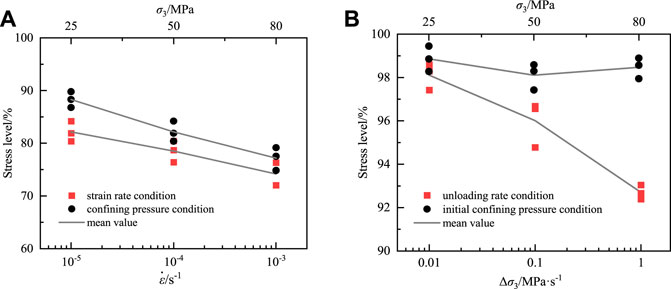
FIGURE 13. Failure precursor stress levels of marbles based on crack strain rate: (A) loading test; (B) unloading test.
5 Conclusion
(1) Under different conditions, stress-strain curves of marbles are similar in the linear stage, but they are significantly affected by initial confining pressure, strain rate, and unloading rate in non-linear and post-peak stages. Under different stress paths, triaxial marble mainly suffers shear failure, and the failure degree under the unloading state is more serious than the loading state. In the loading state, as confining pressure increases and strain rate decreases, the brittle failure degree of marble decreases. In the unloading state, marble is less prone to brittle failure when unloading at a lower unloading rate.
(2) The progressive failure process of marble can be divided into crack closure, linear elastic, crack stable growth, crack rapid growth, and post-peak failure stages based on volume crack strain, correspondingly the characteristic stress thresholds are determined. The higher the strain rate and confining pressure, the higher the stress level of characteristic stress, while the unloading conditions only weakens the peak stress. As stress level rises, deformation modulus decreases, the Poisson ratio increases, and their changing rate in unloading conditions is faster than in loading conditions, indicating that more deformation is generated in marble under unloading conditions, especially under higher unloading rate and lower initial confining pressure.
(3) Introducing the pre-peak volume crack propagation strain without considering initial damage to quantitatively analyze the crack propagation degree of marble before the peak. The lower the confining pressure, the higher the strain rate and unloading rate, and the fewer the cracks generated before the peak. The turning point of volume crack strain rate from stable growth to rapid growth is defined as the failure precursor point of rock. Stress levels of marble failure precursors in loading and unloading conditions are between 70% and 100%, and decrease as the strain rate increases, confining the pressure and unloading rate. In the unloading state, the failure precursor point appears later and is close to the unloading point, showing that unloading rock is more prone to sudden fracture.
Data Availability Statement
The original contributions presented in the study are included in the article/supplementary material, further inquiries can be directed to the corresponding author.
Author Contributions
XL contributed to the conception of the study; YZ, QH, and YX performed the experiment; XL and YZ contributed significantly to the analysis and manuscript preparation; YZ performed the data analyses and wrote the manuscript; JG helped perform the analysis with constructive discussions.
Funding
This research was funded by the Opening Fund of Key Laboratory of Deep Earth Science and Engineering, Ministry of Education, Sichuan University (No. DESE202003), the Key Scientific Research Fund of Xihua University (No. Z17113), and the Research Center for Social Development and Social Risk Control of Sichuan Province, Key Research Base of Philosophy and Social Sciences, Sichuan University (No. SR21A04).
Conflict of Interest
The authors declare that the research was conducted in the absence of any commercial or financial relationships that could be construed as a potential conflict of interest.
Publisher’s Note
All claims expressed in this article are solely those of the authors and do not necessarily represent those of their affiliated organizations, or those of the publisher, the editors and the reviewers. Any product that may be evaluated in this article, or claim that may be made by its manufacturer, is not guaranteed or endorsed by the publisher.
References
Alneasan, M., Behnia, M., and Bagherpour, R. (2019). Analytical and numerical investigations of dynamic crack propagation in brittle rocks under mixed mode loading. Constr. Build. Mat. 222, 544–555. doi:10.1016/j.conbuildmat.2019.06.163
Bieniawski, Z. T. (1967). Mechanism of brittle fracture of rock: Part I-theory of the fracture process. Int. J. Rock Mech. Min. Sci. Geomechanics Abstr. 4 (4), 395–404. doi:10.1016/0148-9062(67)90030-7
Cai, M., and Kaiser, P. K. (2005). Assessment of excavation damaged zone using a micromechanics model. Tunn. Undergr. Space Technol. 20 (4), 301–310. doi:10.1016/j.tust.2004.12.002
Cai, M., Kaiser, P. K., Tasaka, Y., Maejima, T., Morioka, H., Minami, M., et al. (2004). Generalized crack initiation and crack damage stress thresholds of brittle rock masses near underground excavations. Int. J. Rock Mech. Min. Sci. (1997). 41 (5), 833–847. doi:10.1016/j.ijrmms.2004.02.001
Chen, G. Q., Zhang, Y., Li, Y., Pan, Y. G., and Jin, C. Y. (2021). Thermal-acoustic precursor information chain of rock failure under true triaxial loading. Chin. J. Rock Mech. Eng. 40 (9), 1764–1776. doi:10.13722/j.cnki.jrme.2020.0984
Chen, Y. F., Wei, K., Liu, W., Hu, S. H., Hu, R., Zhou, C. B., et al. (2016). Experimental characterization and micromechanical modelling of anisotropic slates. Rock Mech. Rock Eng. 49 (9), 3541–3557. doi:10.1007/s00603-016-1009-x
Chen, Y., and Guo, B. (2020). Crack closure effect and energy dissipation model for rocks under uniaxial compression. Geotech. Geol. Eng. (Dordr). 38 (6), 621–629. doi:10.1007/s10706-019-01051-4
Chen, Y., Zuo, J. P., Li, Z. H., and Dou, R. (2020). Experimental investigation on the crack propagation behaviors of sandstone under different loading and unloading conditions. Int. J. Rock Mech. Min. Sci. (1997). 130, 104310. doi:10.1016/j.ijrmms.2020.104310
Cong, Y., Feng, X. T., Zheng, Y. R., Wang, Z. Q., and Qiu, S. L. (2016). Study on effects of unloading rate on macro-meso failure mechanism of brittle rock. Chin. J. Rock Mech. Eng. 35 (S2), 3696–3705. doi:10.13722/j.cnki.jrme.2015.1159
Dong, L. J., Chen, Y. C., Sun, D. Y., and Zhang, Y. H. (2021c). Implications for rock instability precursors and principal stress direction from rock acoustic experiments. Int. J. Min. Sci. Technol. 31 (5), 789–798. doi:10.1016/j.ijmst.2021.06.006
Dong, L. J., Hu, Q. C., Tong, X. J., and Liu, Y. F. (2020). Velocity-Free MS/AE source location method for three-dimensional hole-containing structures. Engineering 6 (7), 827–834. doi:10.1016/j.eng.2019.12.016
Dong, L. J., Tong, X. J., Hu, Q. C., and Tao, Q. (2021b). Empty region identification method and experimental verification for the two-dimensional complex structure. Int. J. Rock Mech. Min. Sci. (1997). 147, 104885. doi:10.1016/j.ijrmms.2021.104885
Dong, L. J., Tong, X. J., and Ma, J. (2021a). Quantitative investigation of tomographic effects in abnormal regions of complex structures. Engineering 7 (7), 1011–1022. doi:10.1016/j.eng.2020.06.021
Feng, G. L., Chen, B. R., Xiao, Y. X., Jiang, Q., Li, P. X., Zheng, H., et al. (2022). Microseismic characteristics of rockburst development in deep tbm tunnels with alternating soft-hard strata and application to rockburst warning: A case study of the neelum-jhelum hydropower project. Tunn. Undergr. Space Technol. 122, 104398. doi:10.1016/j.tust.2022.104398
Hoek, E., and Martin, C. D. (2014). Fracture initiation and propagation in intact rock - a review. J. Rock Mech. Geotechnical Eng. 6 (4), 287–300. doi:10.1016/j.jrmge.2014.06.001
Ji, W. W., Pan, P. Z., Su, F. S., and Du, M. P. (2016). Failure mechanism of deep-buried marble under loading-unloading conditions based on crack volumetric strain. Rock Soil Mech. 37 (11), 3079–3088. doi:10.16285/j.rsm.2016.11.006
Jin, P. J., Wang, E. Y., and Song, D. Z. (2017). Study on correlation of acoustic emission and plastic strain based on coal-rock damage theory. Geomech. Eng. 12 (4), 627–637. doi:10.12989/gae.2017.12.4.627
Li, A., Liu, Y., Dai, F., Liu, K., and Wei, M. D. (2020). Continuum analysis of the structurally controlled displacements for large- scale underground caverns in bedded rock masses. Tunn. Undergr. Space Technol. 97, 103288. doi:10.1016/j.tust.2020.103288
Li, X. Z., Qi, C. Z., Shao, Z. S., and Ma, C. (2018). Evaluation of strength and failure of brittle rock containing initial cracks under lithospheric conditions. Acta Geophys. 66 (2), 141–152. doi:10.1007/s11600-018-0123-4
Martin, C. D., and Chandler, N. A. (1994). The progressive fracture of Lac Du Bonnet granite. Int. J. Rock Mech. Min. Sci. Geomechanics Abstr. 31 (6), 643–659. doi:10.1016/0148-9062(94)90005-1
Martin, C. D. (1993). The strength of massive lac du bonnet granite around underground openings. Canada: University of Manitoba.
Martino, J. B., and Chandler, N. A. (2004). Excavation-induced damage studies at the underground research laboratory. Int. J. Rock Mech. Min. Sci. (1997). 41 (8), 1413–1426. doi:10.1016/j.ijrmms.2004.09.010
Ulusay, R. (2014). The ISRM suggested methods for rock characterization testing and monitoring 2007-2014. Berlin: Springer.
Xing, H. A., Zhang, Q. B., and Zhao, J. (2018). Stress thresholds of crack development and Poisson ’ s ratio of rock material at high strain rate. Rock Mech. Rock Eng. 51 (3), 945–951. doi:10.1007/s00603-017-1377-x
Yan, Z. L., Dai, F., Zhu, J. B., and Xu, Y. (2021). Dynamic cracking behaviors and energy evolution of multi-flawed rocks under static pre-compression. Rock Mech. Rock Eng. 54 (9), 5117–5139. doi:10.1007/s00603-021-02564-2
Yu, Y., Zhao, D. C., Feng, G. L., Geng, D. X., and Guo, H. S. (2022). Energy evolution and acoustic emission characteristics of uniaxial compression failure of anchored layered sandstone. Front. Earth Sci. (Lausanne). 10, 841598. doi:10.3389/feart.2022.841598
Zhao, P. X., Li, S. G., Ho, C. H., Lin, H. F., and Zhuo, R. S. (2019). Crack propagation and material characteristics of rocklike specimens subject to different loading rates. J. Mat. Civ. Eng. 31 (7), 04019113. doi:10.1061/(ASCE)MT.1943-5533.0002768
Zhou, L., Zhu, Z. M., Qiu, H., Zhang, X. S., and Lang, L. (2018). Study of the effect of loading rates on crack propagation velocity and rock fracture toughness using cracked tunnel specimens. Int. J. Rock Mech. Min. Sci. (1997). 112, 25–34. doi:10.1016/j.ijrmms.2018.10.011
Zhou, X. P., Bi, J., and Qian, Q. H. (2015). Numerical simulation of crack growth and coalescence in rock-Like materials containing multiple pre-existing flaws. Rock Mech. Rock Eng. 48 (3), 1097–1114. doi:10.1007/s00603-014-0627-4
Zhu, Z. H., Yu, L. Y., Li, J. L., Meng, Q. B., Sui, B., and Zhang, Z. Q. (2020). Deformation evolution and dissipated energy characteristicsof marble under pre-peak unloading conditions. J. China Coal Soc 45 (S1), 181–190. doi:10.13225/j.cnki.jccs.SJ20.0122
Zuo, J. P., Chen, Y., and Liu, X. L. (2019). Crack evolution behavior of rocks under confining pressures and its propagation model before peak stress. J. Cent. South Univ. 26 (11), 3045–3056. doi:10.1007/s11771-019-4235-z
Keywords: Jinping marble, loading and unloading, progressive failure, volume crack strain, failure precursor
Citation: Liu X, Zheng Y, Guo J, Hao Q and Xue Y (2022) Deformation and Failure Characteristics of Loading and Unloading Rock Based on Volume Crack Strain. Front. Earth Sci. 10:911823. doi: 10.3389/feart.2022.911823
Received: 03 April 2022; Accepted: 02 June 2022;
Published: 15 August 2022.
Edited by:
Guang-Liang Feng, Institute of Rock and Soil Mechanics (CAS), ChinaReviewed by:
Jianping Zuo, China University of Mining and Technology-Beijing, ChinaLongjun Dong, Central South University, China
Copyright © 2022 Liu, Zheng, Guo, Hao and Xue. This is an open-access article distributed under the terms of the Creative Commons Attribution License (CC BY). The use, distribution or reproduction in other forums is permitted, provided the original author(s) and the copyright owner(s) are credited and that the original publication in this journal is cited, in accordance with accepted academic practice. No use, distribution or reproduction is permitted which does not comply with these terms.
*Correspondence: Xiaohui Liu, liuxh@mail.xhu.edu.cn