Stability analysis of tunnel in sandy cobble strata under different pre-reinforcement techniques
 Xiaobin Li1,2
  Ying Zhao
- 1School of Civil Engineering, Chongqing University, Chongqing, China
- 2Qinghai Xihu Expressway Management Co., Ltd., Xining, China
- 3School of Highway, Chang’an University, Xi’an, China
Excavating tunnels in sandy cobble strata carries a high risk of ground collapse caused by instability of the tunnel face. In order to prevent instability at the tunnel face during excavation, this paper focuses on studying the effects of various pre-reinforcement method on the stability of tunnel in the sand-cobble strata. Firstly, pre-reinforcement projects suitable for these tunnels are proposed. Then, using FLAC3D to established numerical models, then simulate the excavation process under six different working conditions: non-reinforced, pre-reinforcement with advance small pipes, pre-reinforcement with pipe-roof, pre-reinforcement with GFRP bolts, pre-reinforcement with advance small pipes and GFRP bolts, and pre-reinforcement with pipe-roof and GFRP blots. The displacement and stress fields of the soil behind and in front of the tunnel face under each condition are obtained. The results show that the use of GFRP bolts for pre-reinforcement can effectively control the deformation of the surrounding rock in front and behind the tunnel face, and pre-reinforcement with advance small pipes or pipe-roof can reduce the settlement of the tunnel crown. Pre-reinforcement by the combination of GFRP bolts with advance small pipes or pipe-roof can better ensure the stability of the tunnel during the excavation process.
1 Introduction
The sandy cobble stratum is a typical mechanically unstable geological formation (Martí et al., 2008), mainly composed of pebbles, gravels, sands, and a small amount of clay, which are widely distributed in cities such as Beijing, Lanzhou, Chengdu, and Shenyang in China. Tunnels passing through sand-cobble stratum are highly susceptible to disrupting the initial equilibrium state of the formation during excavation, and ground collapse accidents caused by tunnel instability frequently occur in the engineering practice. Without reinforcement measures, existing tunnels in sand-cobble stratum will experience more severe disturbances than those in other geological formations (Liang et al., 2017; Jin et al., 2018; Lin et al., 2021). Therefore, when conducting underground engineering construction in sandy cobble stratum, auxiliary measures such as pre-support or pre-reinforcement should be taken to ensure the stability of the formation and the safety of existing tunnels.
To ensure the stability of the tunnel during excavation, various auxiliary methods have been proposed and applied by many scholars in the industry, including pre-grouting, drift face anchoring, vertical pre-reinforcement technology, pre-grouting, and ground freezing (Lunardi, 2008). Among them, ground pre-grouting and ground freezing methods have been frequently applied to reinforce sandy cobble stratum in recent years and have been proven to be particularly useful in improving the stability of tunnels in sandy cobble stratum during construction (Kang et al., 2021; Mei et al., 2021). Although methods such as ground grouting reinforcement and ground freezing can ensure the stability of the formation during excavation, the construction process is complicated, material waste is serious, and the excavation efficiency is low, which cannot improve the mechanization level of tunnel construction and cannot achieve safe, economic, rapid and efficient construction of tunnels. In this case, a common and economical pre-reinforcement measure is tunnel advance support technology, which can prevent excessive strain during tunnel excavation and maintain the original support capacity of the ground (Shin et al., 2008). Many scholars have conducted research through large-scale field studies (Ocak, 2008; Wang et al., 2016), centrifuge model tests (Hisatake and Ohno, 2008; Juneja et al., 2010; Wong et al., 2012), and numerical simulations (Aksoy and Onargan, 2010; Zhang et al., 2014; Li et al., 2015) to find that the application of pre-support technology greatly improves the stability of the tunnel face.
Although the study of pre-reinforcement technology for tunnels in the sandy cobble stratum is relatively mature, most researchers focus on studying individual reinforcement measures based on the disturbance characteristics of the surrounding rock of existing tunnels (Li et al., 2020; Cao et al., 2021). By analyzing the optimized parameters for various support conditions and conducting numerical simulations of pre-reinforcement methods, they evaluate the reinforcement effect based on the stress and deformation of the surrounding rock and the ground settlement of the tunnel (Yoo and Shin, 2003; Bin et al., 2012; Zhao et al., 2019). However, few researchers have designed multiple pre-reinforcement plans based on engineering geological conditions and project construction characteristics, and compared the comprehensive effects of multiple pre-reinforcement plans. Therefore, various pre-reinforcement measures and their combined comprehensive effects still need further research during the excavation of tunnels in sand-cobble mixed strata.
Based on the complexity of the sand-cobble strata, experimental methods can only provide insights into the mechanical properties of localized sand-cobble mixture. Numerical simulation methods not only enable the establishment of a numerical model for heterogeneous sand-cobble strata, but also allow for the repetition of large-scale numerical experiments. Therefore, numerical simulation methods are better suited for investigating the mechanical properties, deformation characteristics, and stability of sand-cobble strata tunnels (Du et al., 2019). The FLAC3D finite difference software, developed by Itasca, is a continuum mechanics analysis program that can simulate the mechanical properties of various materials such as rock and soil masses, lining, anchor rods, geogrids, etc. It has unique advantages in material elastic-plastic analysis, large deformation analysis, and simulation of construction processes. Some scholars have already used FLAC3D to analyze the stability of tunnels in the sand-cobble mixed strata and obtained good results (Zhang et al., 2019; Cui et al., 2020; Di et al., 2023).
In summary, this study is based on the Da Zhuang tunnel project in Qinghai Province, and designs a pre-reinforcement scheme suitable for tunnel in the sand-cobble mixed stratum based on the geological conditions and construction characteristics of the project. Using the FLAC3D finite difference software, a three-dimensional numerical model is established to investigate the displacement and stress changes of the surrounding rock in front and behind the tunnel face under different working conditions, evaluate the pre-reinforcement effects of different working conditions comprehensively, and propose the optimal pre-reinforcement scheme for the surrounding rock of tunnels in sandy cobble strata. The results can provide valuable experience for similar engineering projects.
2 Design of pre-reinforcement technology
2.1 Project overview
The Da Zhuang Tunnel is a separated middle tunnel located in Xi Shan gen Village, Dong Gou Township, Hu Thu Tu Autonomous County, Qinghai Province. The left line starts at ZK40+366 and ends at ZK40+960, with a length of 594 m. The right line starts at YK40+454 and ends at YK41+126, with a length of 672 m. Both tunnels have a 2.5% one-way slope. The left tunnel has a burial depth of 45.2 m, and the maximum burial depth of the right tunnel is approximately 44.7 m. The entrance and exit adopt end-wall and cut-bamboo style doors respectively, and there is one pedestrian cross passage in the tunnel. The tunnel is illuminated by electric lighting, naturally ventilated, and equipped with self-retaining drainage system.
The geological conditions of the project mainly consist of sand-cobble stratum, with the cobble strata appearing as gray-yellow soil, moderately dense, and mainly composed of cobble, followed by pebbles. Sand particles and powdery clay are used for filling, and the cobble particle size is uneven with irregular shapes, which has a significant impact on the tunnel. The rock mass of the tunnel body is mostly Quaternary Upper Pleistocene alluvial gravel (slightly muddy cemented), with poor surrounding rock stability and a surrounding rock grade of level V. During construction, arches without support are prone to large-scale collapse, and the stability of the side walls is poor. The geological conditions have an extremely unfavorable impact on the blind excavation construction, and the specific situation is shown in Figure 1.
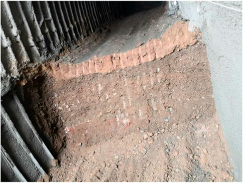
FIGURE 1. Sandy cobble stratum.
2.2 Summary of pre-reinforcement technology
The pre-reinforcement technology originated from the application of the New Austrian Tunneling Method in mountainous tunnels (Han, 1987). It is difficult to ensure the stability of the excavation face solely through initial support in mountainous tunnels with poor geological conditions and at the entrance and exit sections with sandy cobble mixed strata. To ensure the stability of the excavation face in weak geological layers, appropriate pre-reinforcement techniques need to be applied to the strata. Pre-reinforcement measures can be classified into strata improvement and pre-support methods based on their reinforcement mechanisms on the surrounding soil. Strata improvement refers to improving the mechanical properties of the excavation face and the surrounding strata by grouting, drainage consolidation, or freezing (Kang et al., 2021; Mei et al., 2021). Pre-support method is based on the surrounding rock conditions, construction methods, progress requirements, mechanical support, and the environment in which the project is located before tunnel excavation. It chooses simpler or integrated auxiliary construction methods to strengthen the strength of tunnel surrounding rock to ensure that the excavation face remains stable during tunnel excavation, and the surrounding rock does not collapse. Due to the complex construction process and high cost of strata improvement, and its difficulty in implementation, most projects tend to choose pre-support methods to reinforce the soil around the tunnel.
The necessity and degree of advanced pre-support and support should be determined according to the stability of the surrounding rock. The instability of the surrounding rock is caused by the inability of the support structure to provide sufficient support force, which cannot effectively constrain and control the plastic deformation, resulting in the instability of the excavation face. Reasonable excavation face support measures and scientifically reasonable tunnel construction methods can limit the excessive deformation of the surrounding rock of the excavation face. Conversely, it can promote large deformations, even in better geological conditions. Therefore, selecting appropriate pre-reinforcement methods is critical to the stability of the tunnel construction process.
2.3 Design of pre-reinforcement methods
Based on the geological conditions where the engineering project is located, the geological environment is relatively complex due to the presence of sand-cobble strata. The self-bearing capacity of the tunnel in sandy cobble mixed strata is relatively low, and during the tunnel excavation process, the soil within a certain range in front of the face will undergo plastic deformation due to disturbance, significantly increasing the risk of rock instability. Therefore, it is necessary to perform pre-reinforcement of the surrounding rock of the tunnel to change its initial state and enhance its self-bearing capacity, thereby improving the stability of the face. Currently, the main pre-reinforcement methods for tunnel in sandy cobble mixed strata include the use of advance small pipes, pipe-roof and GFRP bolt (Peila, 1994; Yoo, 2002; Funatsu et al., 2008). Advance small pipes, as the main technical means of pre-reinforcement, have been widely used in China. The small pipes, made of steel, typically have a diameter of about
In summary, based on the engineering background of the Da Zhuang Tunnel in Qinghai Province, this study aims to address the issue of advanced support technology for tunnel in the sand-cobble mixed strata. A three-dimensional numerical model will be established using the finite difference software FLAC3D to simulate the effects of six different pre-reinforcement methods on construction stability, including non-reinforced, pre-reinforcement with advance small pipes, pre-reinforcement with pipe-roof, pre-reinforcement with GFRP bolt, pre-reinforcement with advance small pipes and GFRP bolt, and pre-reinforcement with pipe-roof and GFRP blot. Considering the difficulties in drilling and the risk of collapse during construction in sandy cobble mixed strata, reasonable advanced support measures and their parameters will be determined. By comparing and analyzing the displacement and stress changes of the surrounding rock and the tunnel face under the six working conditions during the construction process, the best pre-reinforcement method for this engineering project will be determined, providing valuable reference for similar projects.
3 Numerical modelling of the tunnel
3.1 Methodology for establishing a cobble database
In numerical simulation studies of tunnels in the sand-cobble strata, it is common practice to treat the strata as homogeneous materials and to use comprehensive mechanical parameters such as deformation modulus, cohesive force, and internal friction angle to investigate stability and ground settlement problems caused by tunnel excavation (Zhang et al., 2013; Huang et al., 2019). However, sand-cobble mixed strata are non-homogeneous materials with a large particle size distribution, and their internal microstructural features have an important influence on the overall mechanical properties. Ignoring the existence of large blocks of rock will lead to inaccurate predictions of the stability and deformation of tunnels in sandy cobble stratum during construction. Therefore, to accurately simulate sand-cobble mixture in actual engineering projects, it is necessary to construct a rock model with a similar particle size distribution and randomly shaped rocks. To characterize the true shape characteristics of the rock, this study first analyzes the shape features of actual rock from a quantitative perspective and then uses the discrete Fourier transform to reconstruct a block model and establish a cobble database. The Fourier descriptors have been proven to be able to well describe the real shape of large blocks of rock and generate blocks with specific shapes (Mollon and Zhao, 2012).
To begin, it is necessary to study the shape characteristics of actual rock blocks. In previous studies, Barrett (1980) proposed three shape descriptors (as shown in Figure 2) that can be used to fully describe the shape characteristics of rock blocks, namely, the Form, Roundness and Surface texture. Referring to existing methods (Hentschel and Page, 2003), the form described by flatness (OP) and sphericity (SP), while roundness is described by angularity (AP), concavity (AC), and shape factor (SF). The roughness of the rock is described by the roughness (RO) index. The representation of the above indicators is shown in Figure 3, and can be expressed as:
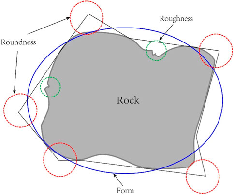
FIGURE 2. Block-shaped information representation symbolization.
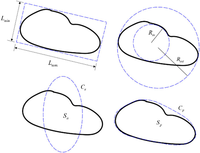
FIGURE 3. Block-shaped information representation symbolization.
Where,
Once the metrics that describe specific shapes of the blocks have been obtained, the block model can be reconstructed using Fourier transform. As shown in Figures 4A, B, the contour of the block can be transformed into a discrete signal. Firstly, the contour of the block
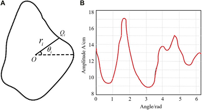
FIGURE 4. Transformation of (A) block outlines and (B) discrete signals.
In the Cartesian coordinate system:
After converting the obtained rock block outline into a discrete signal, the rock block model is reconstructed using the discrete Fourier inverse transform. The distance
Where,
Where,
The coefficients
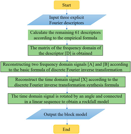
FIGURE 5. The process of reconstructing the block model.
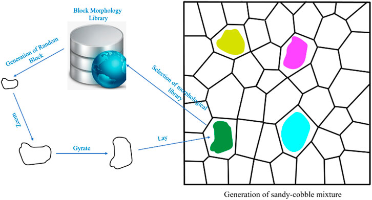
FIGURE 6. Stochastic model generation process for sandy-cobble mixture.
3.2 Numerical simulation
3.2.1 Simulation method
According to the engineering background, the tunnel passes through the sand-cobble stratum, and based on the characteristics of mechanized construction, the stability analysis of surrounding rock under different pre-reinforcement methods is carried out. According to the design requirements, the mechanical construction adopts the core soil method, focusing on the stability of the soil in front of the face. In the numerical simulation, excavation is carried out in steps of 1 m (as shown in Figure 7). The construction steps are as follows: the tunnel is first advanced supported, and the core soil is reserved by excavating the upper step, then concrete is sprayed in a timely manner, followed by the installation of steel supports and timely locking of foot anchor rods, and then the system anchor rods and steel mesh are laid. Afterwards, concrete is sprayed to the design thickness. Then, the core soil is excavated with a lag of 3–5 m, and the lower step excavation is carried out, followed by immediate support after excavation completion. After the lower cross-section support is completed, the bottom plate support is carried out, followed by the tight-fitting of the bottom plate concrete and steel-reinforced concrete lining.
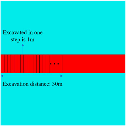
FIGURE 7. Details of excavation.
3.2.2 Modelling
A numerical model of the tunnel face in sand-cobble strata with various reinforcement measures was established using the finite difference software FLAC3D. The influence of different pre-reinforcement measures on Earth pressure and instability area was investigated. According to the geological survey report of the dependent project, we designed the 3D numerical model of the tunnel in sand-cobble mixed strata shown in Figure 8. The model simplifies the surrounding soil of the tunnel into a binary soil consisting of sand and cobble, and based on the method of establishing a cobble database in Section 3.1, establishes a sand-cobble strata model with a stone content of 10%. The model size is
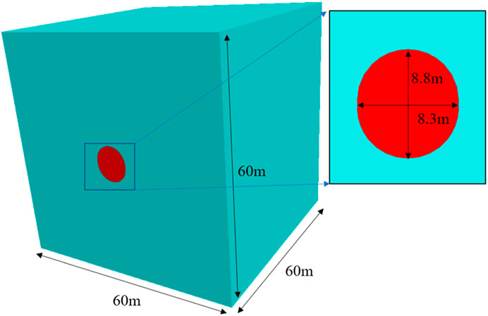
FIGURE 8. Numerical model.
3.2.3 Material parameters
In order to reflect the physical and mechanical parameters of the surrounding rock of the excavation area of the tunnel, the parameters of the superficial soil were determined based on the geological survey report and the specifications (Transportation Department of the People’s Republic of China, 2010), and the material parameters used are shown in Table 1. The parameters of the pre-reinforcement measures were based on similar engineering experiences, and the main supporting parameters are shown in Table 2 and Table 3.

TABLE 1. Mechanical parameters of the sandy cobble strata.
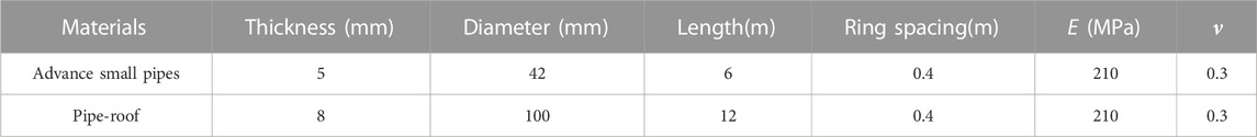
TABLE 2. Physical and mechanical parameters of pre-reinforced materials.
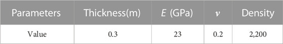
TABLE 3. Physical parameters of lining.
3.3 Simulation working conditions
To further investigate the impact of different pre-reinforcement measures on the excavation stability of sand and gravel formations in tunnels, numerical simulations were performed on a tunnel model with a 10% stone content, under six pre-reinforcement conditions: non-reinforced, pre-reinforcement with advance small pipes, pre-reinforcement with pipe-roof, pre-reinforcement with GFRP bolt, pre-reinforcement with advance small pipes and GFRP bolt, and pre-reinforcement with pipe-roof and GFRP blot. The numerical models of the six pre-reinforcement conditions are shown in Figure 9.
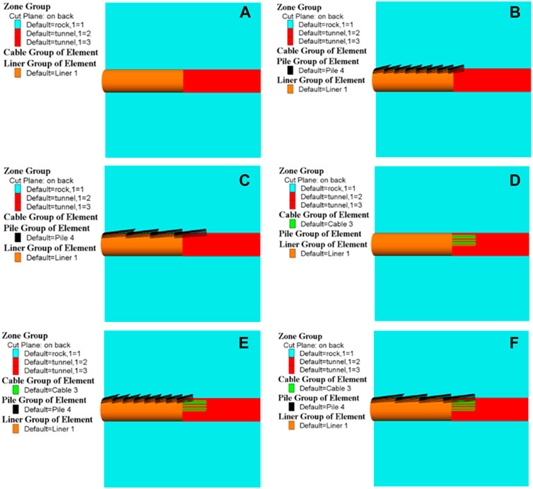
FIGURE 9. Numerical model of pre-reinforcement for different working conditions of (A) conditions 1, (B) conditions 2, (C) conditions 3, (D) conditions 4, (E) conditions 5 and (F) conditions 6.
Condition 1:. Excavation with no reinforcement of the surrounding geological formation.
Condition 2:. Excavation supported by advance small pipes. The pipe is 6 m in length and has a 2 m overlapping section.
Condition 3:. Excavation supported by pipe-roof. Each pipe segment is 12 m in length and has a 3 m overlapping section.
Condition 4:. Excavation supported by glass fiber reinforced plastic (GFRP) rock bolts. Each bolt is 15 m in length and has a 3 m overlapping section.
Condition 5:. Excavation supported by a combination of advance small pipes and GFRP bolts. The green parts represent GFRP bolts, each of which is 15 m in length with a 3 m overlapping section. The black parts represent the s advance small pipes, which is 6 m in length with a 2 m overlapping section.
Condition 6:. Excavation supported by a combination of pipe-roof and GFRP bolts. The green parts represent GFRP bolts, each of which is 15 m in length with a 3 m overlapping section. The black parts represent the pipe-roof, with each segment being 12 m in length and having a 3 m overlapping section.
3.4 Layout of monitoring points
In previous studies, many scholars analyzed the evolution law of ground deformation during the instability process of sand-cobble strata in tunnel face, and found that the rock in front and behind the tunnel face would undergo deformation. In relatively loose sand-cobble strata, the deformation of the rock in front and behind the tunnel face is more significant (Di et al., 2022). Considering the deformation law of the ground in the instability and failure process of the tunnel, the monitoring points in the numerical experiments were arranged as shown in Figure 10. Three monitoring points were vertically set above the arch crown behind the tunnel face, and five monitoring points were uniformly set vertically at the location of the core soil in front of the tunnel face to be excavated. The distance between each monitoring point was 2.2 m, and one monitoring point was set 1 m above the core soil to be excavated and below the crown. A 20 m measuring line was also set in the excavation area. By analyzing the displacement and stress changes of the monitoring points under different pre-reinforcement projects, the stability of tunnel excavation under different conditions was studied.
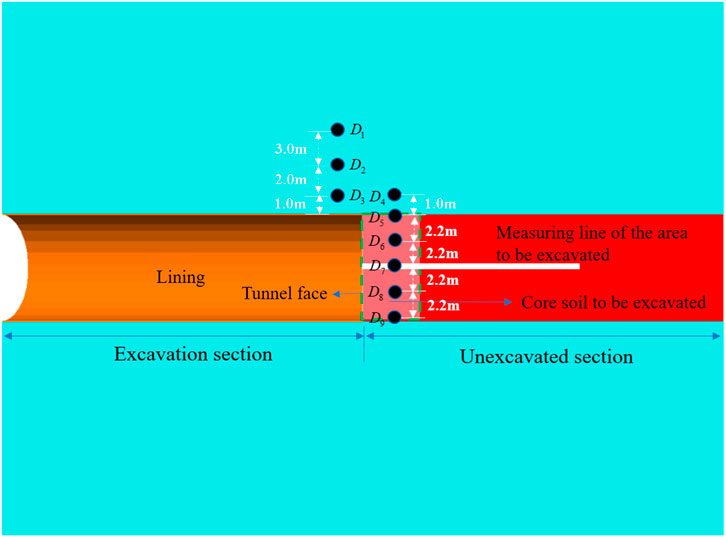
FIGURE 10. Arrangement of monitoring points.
4 Numerical modelling results and discussions
4.1 Validation for numerical tests
Figure 11 shows the horizontal and vertical displacement contour maps of tunnel in the sandy cobble mixed strata with 10% stone content under Working condition 1. It can be observed that the maximum horizontal displacement occurs at the tunnel face, while the vertical displacement mainly occurs at the tunnel crown and the tunnel invert, where the tunnel crown undergoes settlement and the tunnel invert experiences uplift. The variation in horizontal and vertical displacement of the tunnel surrounding rock and the soil in front of the tunnel face during tunnel excavation is consistent with existing numerical test results (Wang et al., 2020). Therefore, it can be concluded that the numerical model proposed in this study can accurately reflect the deformation characteristics of the tunnel in sandy cobble stratum during excavation.
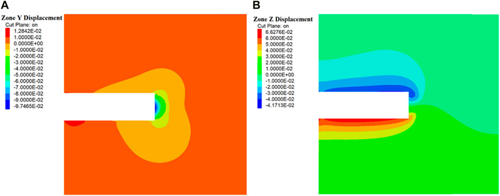
FIGURE 11. (A) Horizontal displacement and (B) vertical displacement clouds without reinforcement.
4.2 Displacement analysis
4.2.1 Surrounding rocks deformation under different working conditions
Displacement is the most commonly used, intuitive, and convenient monitoring indicator during underground construction. The effectiveness of tunnel pre-reinforcement measures in controlling the displacement deformation of surrounding rocks can be reflected by monitoring the horizontal displacement of the tunnel face, surface displacement, and settlement displacement of the front and rear arch crowns of the tunnel face. In order to analyze the deformation characteristics of surrounding rocks under different pre-reinforcement schemes and study their impact on the stability of a tunnel in sandy cobble mixed strata, numerical models were established for different pre-reinforcement methods. The overall displacement contour map, vertical displacement contour map, and horizontal displacement contour map of the tunnel excavation under different pre-reinforcement scheme conditions were calculated and presented in Figures 12–14, respectively.
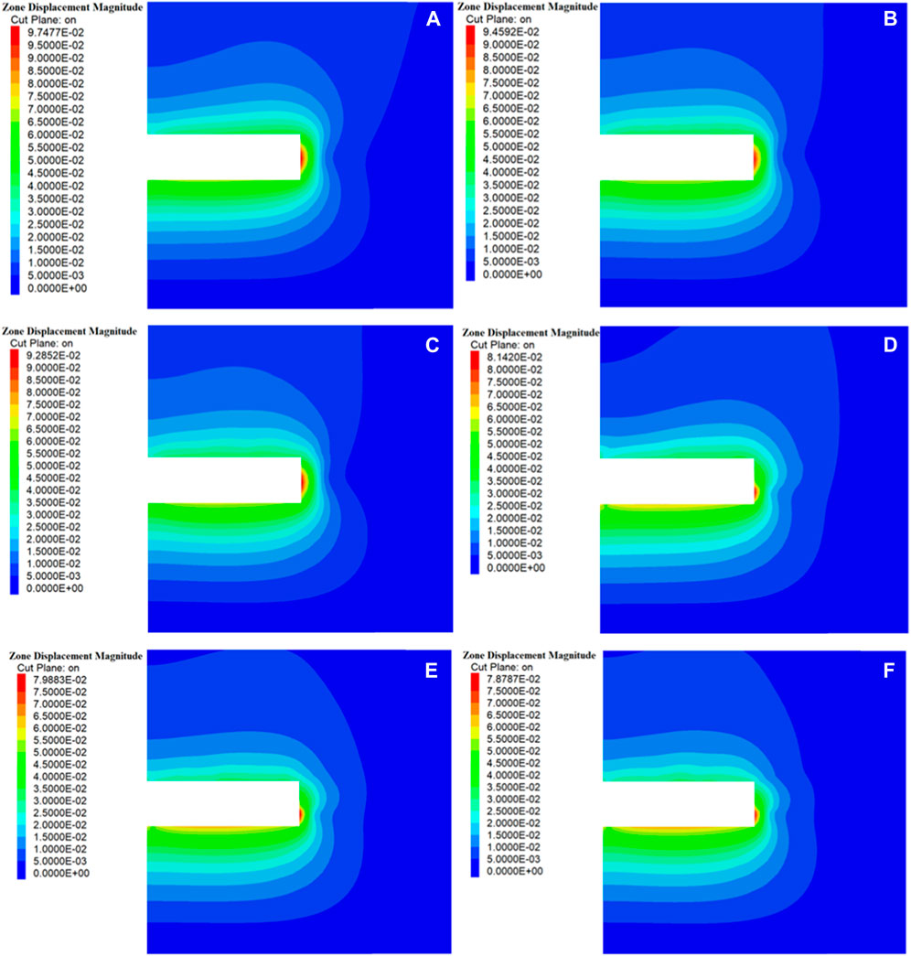
FIGURE 12. Overall displacement cloud of surrounding rock under various working conditions of (A) conditions 1, (B) conditions 2, (C) conditions 3, (D) conditions 4, (E) conditions 5 and (F) conditions 6.
According to Figure 12, it can be seen that under various working conditions, the deformation of the tunnel surrounding rock mainly occurs at the tunnel surrounding rock and the tunnel face, and the red area is mainly concentrated at the soil in front of the tunnel face. Therefore, the displacement at the soil in front of the tunnel face is the largest. In working conditions 1–3, the red area is mainly concentrated at the center of the tunnel face, and the maximum displacement during the excavation process is located at the center of the tunnel face. Compared with working conditions 1–3, when simulating with working conditions 4–6, the red area is reduced and mainly concentrated below the tunnel face. The displacement of the soil in front of the tunnel face is reduced, and the maximum displacement occurs at the lower part of the tunnel face. From Figure 13, it can be seen that the vertical displacement of the surrounding rock mainly occurs at the top and bottom of the tunnel, the top sinking and the bottom uplifting, and the displacement of the bottom uplifting is greater than the sinking of the top. When there is no reinforcement in the strata, the vertical displacement of the tunnel surrounding rock is relatively large compared to other reinforced measures. When simulating with working conditions 2 and 3, the vertical displacement of the tunnel surrounding rock is reduced. When simulating with working conditions 4–6, the range of maximum vertical displacement of the tunnel surrounding rock is significantly reduced compared to working conditions 1–3. From Figure 14, it can be seen that the horizontal displacement is the largest at the tunnel face, and the displacement of the tunnel surrounding rock is relatively small. Under working conditions 1–3, the horizontal displacement mainly occurs at the center position of the heading face, while under working conditions 4–6, the horizontal displacement mainly occurs below the tunnel face, and the deformation area is significantly reduced compared to working conditions 1–3. It can be found that using advance small pipes and pipe-roof for pre-support can reduce the deformation of the tunnel surrounding rock and the tunnel face. Using GFRP bolts, advance small pipes and GFRP bolts, pipe-roof and GFRP blots for support can achieve better results.
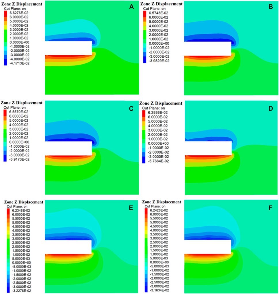
FIGURE 13. Vertical displacement cloud of surrounding rock under various working conditions of (A) conditions 1, (B) conditions 2, (C) conditions 3, (D) conditions 4, (E) conditions 5 and (F) conditions 6.
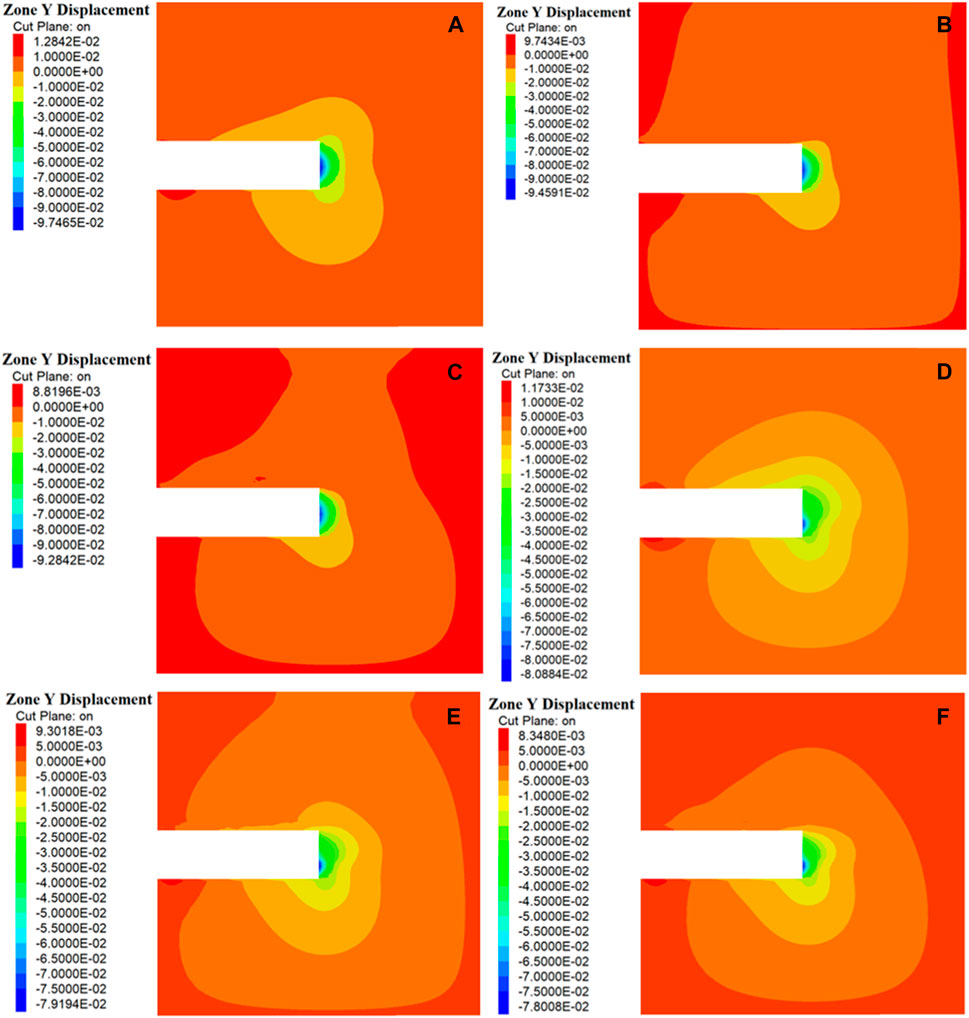
FIGURE 14. Horizontal displacement cloud of surrounding rock under various working conditions of (A) conditions 1, (B) conditions 2, (C) conditions 3, (D) conditions 4, (E) conditions 5 and (F) conditions 6.
4.2.2 Deformation characteristics of the rock in front of the tunnel face
The vertical and horizontal displacement changes of the soil mass in front of the tunnel face are shown in Figure 15A–C and Figure 16A–C, respectively. From Figures 15A, B, it can be observed that under Condition 1, the maximum settlement of the tunnel arch is 30.04 mm, and the maximum uplift of the invert is 38.85 mm. Under Conditions 2 and 3, the maximum settlement of the tunnel arch decreases to 27.82 and 27.32 mm, respectively, while the maximum uplift of the invert remains almost unchanged compared to Condition 1. When the pre-strengthening methods of Conditions 4, 5, and 6 are used, the settlement of the arch decreases to 18.44, 16.33, and 15.99 mm, respectively. Compared with Conditions 1–3, the maximum uplift displacement of the invert decreases to 32.94, 33.37, and 33.56 mm, respectively. As clearly shown in Figure 15C, the vertical displacement of the core soil in front of the tunnel face is reduced when pre-reinforcement methods of Conditions 4–6 are employed.
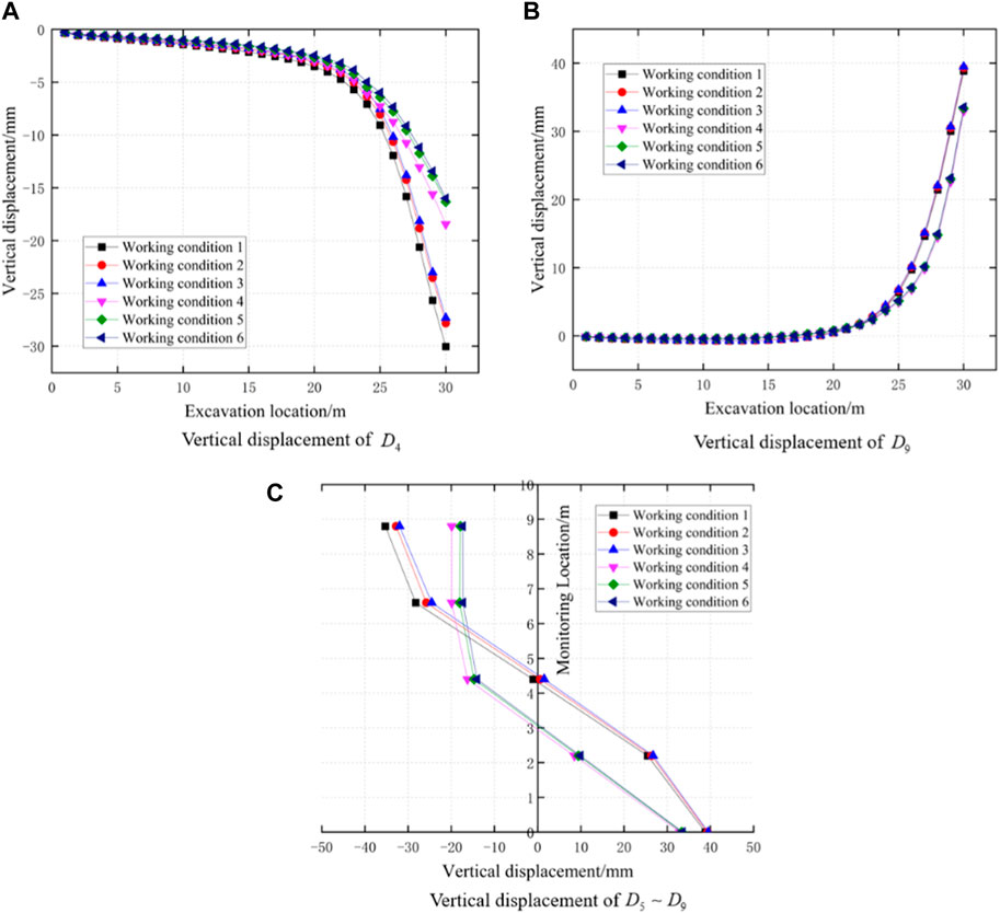
FIGURE 15. Change of vertical displacement of (A) D4, (B) D9 and (C) D5∼D9.
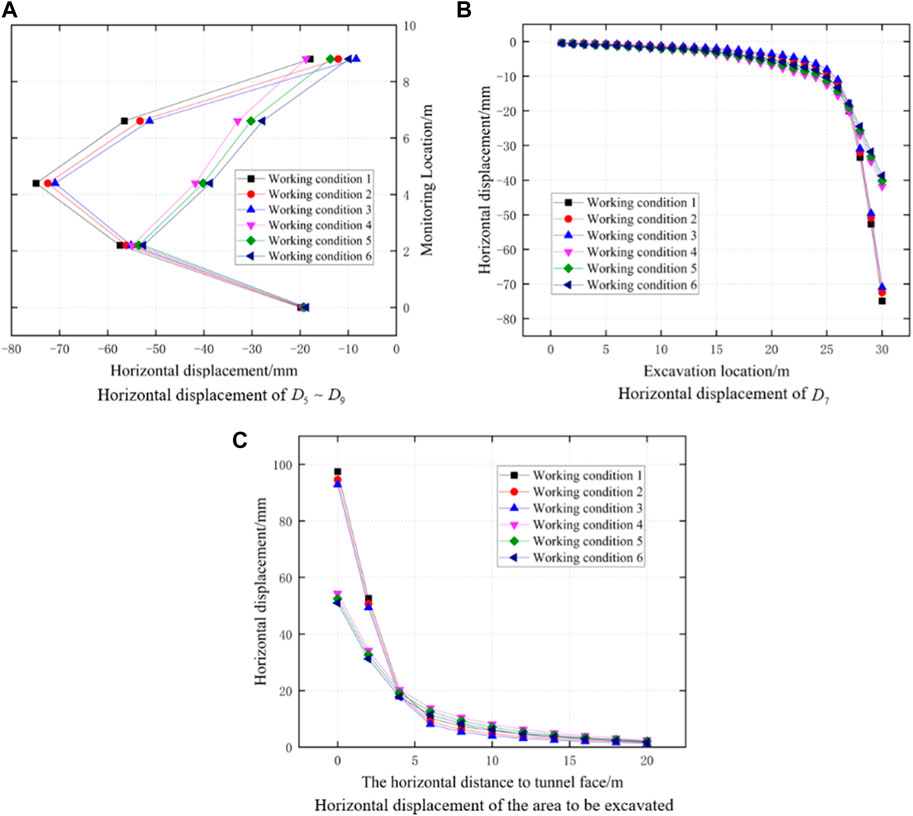
FIGURE 16. Change of horizontal displacement of (A) D5∼D9, (B) D7 and (C) the area to be excavated.
From Figure 16A, the expansion deformation of the tunnel face under different conditions can be clearly observed. When the strata are not reinforced, the expansion displacement of the tunnel face is significant. Under Conditions 2 and 3, there is little improvement in the expansion deformation of the tunnel face compared to Condition 1. The maximum extrusion displacement of the tunnel face under Conditions 1–3 occurs at the center position of the tunnel face. Under Conditions 4–6, the expansion displacement of the tunnel face decreases significantly, and the extrusion deformation of the three conditions is basically the same. At the same time, the location of the maximum deformation of the tunnel face shifts downward. From Figures 16B, C, it can be observed that the horizontal displacement at the midpoint of the core soil in front of the tunnel face is significantly reduced when using glass fiber anchor rods. The horizontal displacement at the center point of the core soil in front of the tunnel face decreases as the distance from the tunnel face increases, with the displacement being greatest at the tunnel face. The experimental results indicate that GFRP blots can effectively control the extrusion deformation of the tunnel face. This is mainly because GFRP blots can improve the shear strength of the core soil to be excavated, which keeps most of the strata near the tunnel face in an elastic stress state, thereby limiting the extrusion expansion deformation of the tunnel face. In addition, GFRP blots have strong bonding properties (Li et al., 2023), which can be used to bond with the soil and apply a restraining force on the soil in front of the tunnel face through the anchoring effect of the anchor rods, thereby suppressing the extrusion deformation of the tunnel face.
4.2.3 Deformation characteristics of the rock behind the tunnel face
The vertical displacement of the soil behind the tunnel face is shown in Figure 17. When the stratum is not reinforced, the maximum settlement occurs in the soil behind the tunnel face. The maximum settlements of the monitoring points
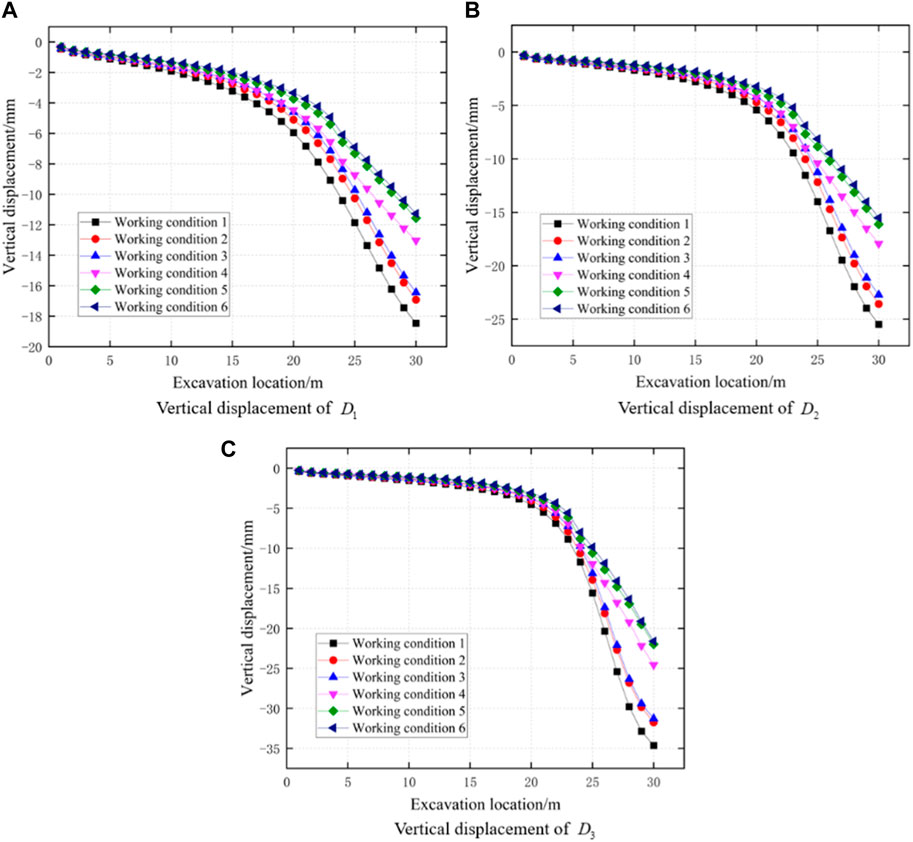
FIGURE 17. Change of vertical displacement of (A) D1, (B) D2 and (C) D3.
Based on the analysis of deformation of tunnel surrounding rock and face under different working conditions as mentioned above, it was found that the reinforcement of advance small pipes and pipe-roof can reduce the settlement of the tunnel vault; GFRP blots are superior to advance small pipes and pipe-roof in controlling face deformation; the comprehensive reinforcement method using GFRP blots and advance small pipes or pipe-roof can better ensure the stability of the tunnel during excavation.
4.3 Stress analysis
4.3.1 Surrounding rocks stress under different working conditions
The vertical stress cloud map and horizontal stress cloud map of the tunnel surrounding rock during excavation under different working conditions were obtained through FLAC3D, as shown in Figures 18, 19. Overall, the horizontal stress of the surrounding rock is smaller than the vertical stress, and the horizontal stress and vertical stress of the surrounding rock are distributed relatively evenly. The overlying soil layer of the tunnel surrounding rock decreases vertically with the distance from the tunnel roof. The overlying soil layer close to the tunnel roof has obvious disturbance during the excavation process, while this phenomenon is not so evident for the soil layer far from the roof. Observing the stress at the tunnel face, it can be seen that the stress of the soil in front of the tunnel face is relatively small. The mechanical properties of the surrounding rock at the tunnel face under working conditions 4–6 have been improved due to the effective reinforcement of the GFRP blots in controlling the deformation caused by the excavation of the tunnel face (Chen et al., 2008).
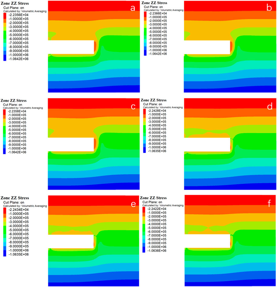
FIGURE 18. Vertical stress cloud of surrounding rock under various working conditions of (A) conditions 1, (B) conditions 2, (C) conditions 3, (D) conditions 4, (E) conditions 5 and (F) conditions 6.
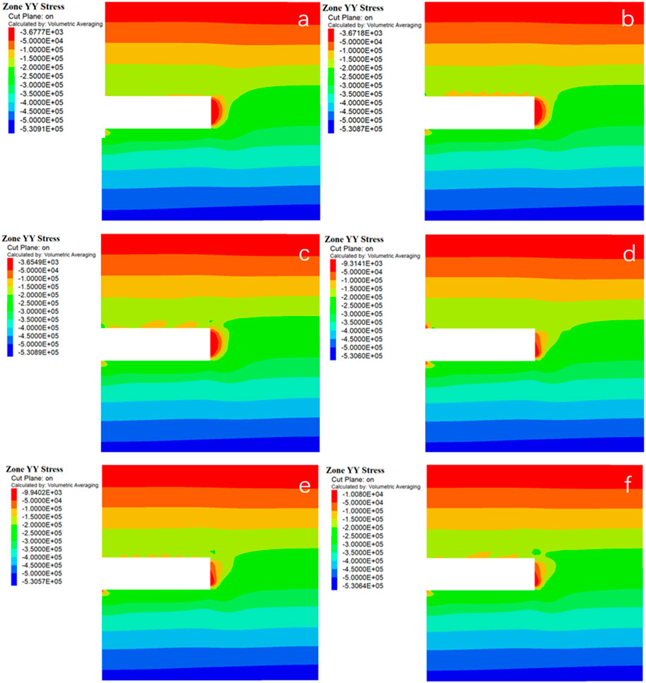
FIGURE 19. Horizontal stress cloud of surrounding rock under various working conditionsof (A) conditions 1, (B) conditions 2, (C) conditions 3, (D) conditions 4, (E) conditions 5 and (F) conditions 6.
4.3.2 Stress characteristics of the rock in front of the tunnel face
The changes in vertical and horizontal stress at monitoring points
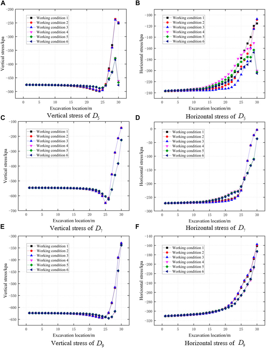
FIGURE 20. Change of vertical stress of (A) D5, (C) D7, (E) D9 and horizontal stress of (B) D5, (D) D7, (F) D9.
4.3.3 Stress characteristics of the rock behind the tunnel face
The stress changes of the surrounding rock behind the palm surface are shown in Figure 21. When the geological strata are not reinforced, the vertical stress of the soil behind the palm surface gradually decreases with increasing depth. When using pre-support methods such as advance small guide pipes or pipe sheds, the vertical stress at monitoring points
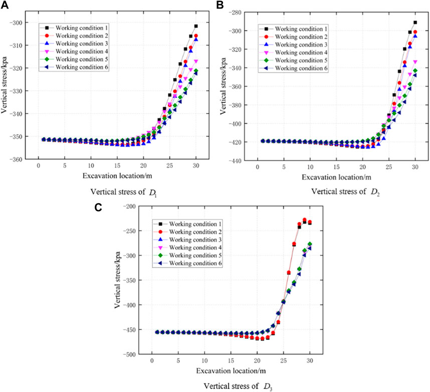
FIGURE 21. Change of vertical stress of (A) D1, (B) D2 and (C) D3.
5 Conclusion
Based on the Da Zhuang tunnel project in Qinghai Province, this paper uses the FLAC3D finite difference software to simulate the tunnel in the sand-cobble mixed strata and analyze the deformation and stress of the tunnel face and surrounding rock under different pre-reinforcement conditions. The following conclusions are drawn:
(1) Without pre-reinforcement, the tunnel in the sandy cobble stratum is prone to rock instability and effective pre-reinforcement measures must be taken based on the site geological conditions. Meanwhile, in addition to the pre-reinforcement around the tunnel, the tunnel face should also be reinforced to ensure construction safety.
(2) All pre-reinforcement measures can control the settlement and failure of surrounding rocks to some extent. However, using only the pipe-roof or advanced small pipes alone is basically ineffective in controlling extrusion deformation and failure at the tunnel face.
(3) Reinforcing the core soil in front of the excavation face with GFRP blots can significantly improve the mechanical performance of the surrounding rock, control the arch failure of the surrounding rock, and reduce the horizontal displacement and surface settlement of the tunnel face and the sinking displacement of the front and rear arches.
(4) Comprehensive reinforcement with pipe-roof and GFRP blots, or advanced small pipes and GFRP blots, can better control the settlement and deformation of the front and rear soil at the tunnel face, reduce the extrusion displacement of the tunnel face, and the pre-reinforcement effect is better than using only glass fiber anchor rods for support.
Data availability statement
The raw data supporting the conclusion of this article will be made available by the authors, without undue reservation.
Author contributions
XL: methodology, writing—original draft. YZ: software, formal analysis, methodology, writing—review and editing. HX: investigation, resources. LZ: investigation, resources. XG: investigation, resources. All authors contributed to the article and approved the submitted version.
Funding
This research is financially supported by the Key R&D and Transformation Plan of Qinghai Province (Grant No. 2021-SF-167).
Conflict of interest
Authors XL, HX, LZ, and XG were employed by the company Qinghai Xihu Expressway Management Co., Ltd.
The remaining author declares that the research was conducted in the absence of any commercial or financial relationships that could be construed as a potential conflict of interest.
Publisher’s note
All claims expressed in this article are solely those of the authors and do not necessarily represent those of their affiliated organizations, or those of the publisher, the editors and the reviewers. Any product that may be evaluated in this article, or claim that may be made by its manufacturer, is not guaranteed or endorsed by the publisher.
References
Aksoy, C. O., and Onargan, T. U. R. G. A. Y. (2010). The role of umbrella arch and face bolt as deformation preventing support system in preventing building damages. Tunn. Undergr. space Technol. 25 (5), 553–559. doi:10.1016/j.tust.2010.03.004
Barrett, P. J. (1980). The shape of rock particles, a critical review. Sedimentology 27 (3), 291–303. doi:10.1111/j.1365-3091.1980.tb01179.x
Bin, L., Taiyue, Q., Wang, Z., and Longwei, Y. (2012). Back analysis of grouted rock bolt pullout strength parameters from field tests. Tunn. Undergr. Space Technol. 28, 345–349. doi:10.1016/j.tust.2011.11.004
Cao, R., Peng, L., and Zhao, Y. (2021). Control of strata deformation in subway interval tunnels crossing a high-speed rail shield tunnel at a short distance. Arabian J. Sci. Eng. 46, 5013–5022. doi:10.1007/s13369-020-05225-8
Chen, T., Mei, Z., and Li, C. (2008). Application research of full section pre reinforcement technology with glass fiber anchor in tunnel. Mod. Tunn. Technol. 45, 226–231.
Cui, J., Xu, W. H., Fang, Y., Tao, L. M., and He, C. (2020). Performance of slurry shield tunnelling in mixed strata based on field measurement and numerical simulation. Adv. Mater. Sci. Eng., 2020, 1–14. doi:10.1155/2020/6785260
Das, N. (2007). Modelling three-dimensional shape of sand grains using discrete element method. Tampa, Florida: University of South Florida.
Di, Q., Li, P., Zhang, M., and Cui, X. (2023). Experimental investigation of face instability for tunnels in sandy cobble strata. Undergr. Space 10, 199–216. doi:10.1016/j.undsp.2022.10.004
Di, Q., Li, P., Zhang, M., and Cui, X. (2022). Influence of relative density on deformation and failure characteristics induced by tunnel face instability in sandy cobble strata. Eng. Fail. Anal. 141, 106641. doi:10.1016/j.engfailanal.2022.106641
Du, X., Zhang, P., Jin, L., and Lu, D. (2019). A multi-scale analysis method for the simulation of tunnel excavation in sandy cobble stratum. Tunn. Undergr. Space Technol. 83, 220–230. doi:10.1016/j.tust.2018.09.019
Funatsu, T., Hoshino, T., Sawae, H., and Shimizu, N. (2008). Numerical analysis to better understand the mechanism of the effects of ground supports and reinforcements on the stability of tunnels using the distinct element method. Tunn. Undergr. Space Technol. 23 (5), 561–573. doi:10.1016/j.tust.2007.10.003
Hentschel, M. L., and Page, N. W. (2003). Selection of descriptors for particle shape characterization. Part. Part. Syst. Charact. Meas. Descr. Part. Prop. Behav. Powders Other Disperse Syst. 20 (1), 25–38. doi:10.1002/ppsc.200390002
Hisatake, M., and Ohno, S. (2008). Effects of pipe roof supports and the excavation method on the displacements above a tunnel face. Tunn. Undergr. Space Technol. 23 (2), 120–127. doi:10.1016/j.tust.2007.02.002
Huang, J., Zhang, Y., Ouyang, X., and Xu, G. (2019). Lagged settlement in sandy cobble strata and Earth pressure on shield tunnel. Math. Biosci. Eng. 16 (6), 6209–6230. doi:10.3934/mbe.2019309
Jin, D., Yuan, D., Li, X., and Zheng, H. (2018). Analysis of the settlement of an existing tunnel induced by shield tunneling underneath. Tunn. Undergr. Space Technol. 81, 209–220. doi:10.1016/j.tust.2018.06.035
Juneja, A., Hegde, A., Lee, F. H., and Yeo, C. H. (2010). Centrifuge modelling of tunnel face reinforcement using forepoling. Tunn. Undergr. Space Technol. 25 (4), 377–381. doi:10.1016/j.tust.2010.01.013
Kang, Y., Hou, C., Li, K., Liu, B., and Sang, H. (2021). Evolution of temperature field and frozen wall in sandy cobble stratum using LN2 freezing method. Appl. Therm. Eng. 185, 116334. doi:10.1016/j.applthermaleng.2020.116334
Li, B., Hong, Y., Gao, B., Qi, T. Y., Wang, Z. Z., and Zhou, J. M. (2015). Numerical parametric study on stability and deformation of tunnel face reinforced with face bolts. Tunn. Undergr. Space Technol. 47, 73–80. doi:10.1016/j.tust.2014.11.008
Li, H., Fu, J., Chen, B., Zhang, X., Zhang, Z., and Lang, L. (2023). Mechanical properties of GFRP bolts and its application in tunnel face reinforcement. Materials 16 (6), 2193. doi:10.3390/ma16062193
Li, R., Zhang, D., Fang, Q., Liu, D., Luo, J., and Fang, H. (2020). Mechanical responses of closely spaced large span triple tunnels. Tunn. Undergr. Space Technol. 105, 103574. doi:10.1016/j.tust.2020.103574
Liang, R., Xia, T., Huang, M., and Lin, C. (2017). Simplified analytical method for evaluating the effects of adjacent excavation on shield tunnel considering the shearing effect. Comput. Geotechnics 81, 167–187. doi:10.1016/j.compgeo.2016.08.017
Lin, Q., Lu, D., Lei, C., Tian, Y., Gong, Q., and Du, X. (2021). Model test study on the stability of cobble strata during shield under-crossing. Tunn. Undergr. Space Technol. 110, 103807. doi:10.1016/j.tust.2020.103807
Lunardi, P. (2008). Design and construction of tunnels: Analysis of controlled deformations in rock and soils (ADECO-RS. Berlin, Germany: Springer Science and Business Media.
Martí, D., Carbonell, R., Flecha, I., Palomeras, I., Font-Capó, J., Vázquez-Suñé, E., et al. (2008). High-resolution seismic characterization in an urban area: Subway tunnel construction in Barcelona. Spain. Geophysics 73 (2), B41–B50. doi:10.1190/1.2832626
Mei, Y., Zhang, X., Nong, X., and Fu, L. (2021). Experimental study of the comprehensive technology of grouting and suspension under an operating railway in the cobble stratum. Transp. Geotech. 30, 100612. doi:10.1016/j.trgeo.2021.100612
Mitarashi, Y., Matsuo, T., Tezuka, H., Okamoto, T., Nishimura, S., and Matsui, T. (2003). Evaluation of effect of long face reinforcement method (FIT method) in tunneling. Dob. Gakkai Ronbunshu 2003 (743), 213–222. doi:10.2208/jscej.2003.743_213
Mollon, G., and Zhao, J. (2012). Fourier-Voronoi-based generation of realistic samples for discrete modelling of granular materials. Granul. Matter 14 (05), 621–638. doi:10.1007/s10035-012-0356-x
Ocak, I. (2008). Control of surface settlements with umbrella arch method in second stage excavations of Istanbul Metro. Tunn. Undergr. Space Technol. 23 (6), 674–681. doi:10.1016/j.tust.2007.12.005
Peila, D. (1994). A theoretical study of reinforcement influence on the stability of a tunnel face. Geotechnical Geol. Eng. 12, 145–168. doi:10.1007/bf00426984
Shin, J. H., Choi, Y. K., Kwon, O. Y., and Lee, S. D. (2008). Model testing for pipe-reinforced tunnel heading in a granular soil. Tunn. Undergr. Space Technol. 23 (3), 241–250. doi:10.1016/j.tust.2007.04.012
Tonon, F. (2010). Sequential excavation, NATM and ADECO: What they have in common and how they differ. Tunn. Undergr. Space Technol. 25 (3), 245–265. doi:10.1016/j.tust.2009.12.004
Wang, Y. S., Yang, C., Zhang, X. S., Zhang, H., and He, S. S. (2020). Stability evaluation method of tunnel face constructed by mining method in sandy pebble stratum. Railw. Eng. (12), 57–60.
Wang, Z., Wang, L. Z., Wang, J. C., and Li, L. L. (2016). Case study of rehabilitation of a damaged underwater tunnel in the construction phase. J. Perform. Constr. Facil. 30 (1), C4014003. doi:10.1061/(asce)cf.1943-5509.0000648
Wong, K. S., Ng, C. W. W., Chen, Y. M., and Bian, X. C. (2012). Centrifuge and numerical investigation of passive failure of tunnel face in sand. Tunn. Undergr. Space Technol. 28, 297–303. doi:10.1016/j.tust.2011.12.004
Yoo, C. (2002). Finite-element analysis of tunnel face reinforced by longitudinal pipes. Comput. Geotechnics 29 (1), 73–94. doi:10.1016/s0266-352x(01)00020-9
Yoo, C., and Shin, H. K. (2003). Deformation behaviour of tunnel face reinforced with longitudinal pipes—Laboratory and numerical investigation. Tunn. Undergr. Space Technol. 18 (4), 303–319. doi:10.1016/s0886-7798(02)00101-3
Zhang, C., Cai, Y., and Zhu, W. (2019). Numerical study and field monitoring of the ground deformation induced by large slurry shield tunnelling in sandy cobble ground. Adv. Civ. Eng., 2019, 1–12. doi:10.1155/2019/4145721
Zhang, X., Wang, M., Lyu, C., Tong, J., Yu, L., and Liu, D. (2022). Experimental and numerical study on tunnel faces reinforced by horizontal bolts in sandy ground. Tunn. Undergr. Space Technol. 123, 104412. doi:10.1016/j.tust.2022.104412
Zhang, Z., Li, H., Liu, H., Li, G., and Shi, X. (2014). Load transferring mechanism of pipe umbrella support in shallow-buried tunnels. Tunn. Undergr. Space Technol. 43, 213–221. doi:10.1016/j.tust.2014.05.018
Zhang, Z. X., Zhang, H., and Yan, J. Y. (2013). A case study on the behavior of shield tunneling in sandy cobble ground. Environ. Earth Sci. 69, 1891–1900. doi:10.1007/s12665-012-2021-4
Keywords: sandy cobble strata, numerical simulation-, pre-reinforcement techniques, face stability, stone content
Citation: Li X, Zhao Y, Xue H, Zhang L and Gong X (2023) Stability analysis of tunnel in sandy cobble strata under different pre-reinforcement techniques. Front. Earth Sci. 11:1212726. doi: 10.3389/feart.2023.1212726
Received: 26 April 2023; Accepted: 01 June 2023;
Published: 23 June 2023.
Edited by:
Yuwei Zhang, Xi’an University of Architecture and Technology, ChinaReviewed by:
Jin-Shuai Zhao, Jiangsu University, ChinaShengzhi Wu, Shandong Jianzhu University, China
Copyright © 2023 Li, Zhao, Xue, Zhang and Gong. This is an open-access article distributed under the terms of the Creative Commons Attribution License (CC BY). The use, distribution or reproduction in other forums is permitted, provided the original author(s) and the copyright owner(s) are credited and that the original publication in this journal is cited, in accordance with accepted academic practice. No use, distribution or reproduction is permitted which does not comply with these terms.
*Correspondence: Ying Zhao, zhaoying856@126.com