Mechanical performance and failure mechanism of U-steel support structure under blast loading
 Jin-Shuai Zhao
 Jia-Hao Yang1
  Peng-Xiang Li
 Xin-Hao Zhu
- 1Faculty of Civil Engineering and Mechanics, Jiangsu University, Zhenjiang, China
- 2Key Laboratory of Geotechnical Mechanics and Engineering of Ministry of Water Resources, Yangtze River Scientific Research Institute, Wuhan, China
- 3College of Urban Construction, Heze University, Heze, China
- 4State Key Laboratory of Geomechanics and Geotechnical Engineering, Institute of Rock and Soil Mechanics, Chinese Academy of Sciences, Wuhan, China
- 5Xi’an Research Institute, China Coal Technology and Engineering Group Corporation, Xi’an, China
- 6PowerChina Huadong Engineering Corporation Limited, Hangzhou, China
The U-steel support structures of underground caverns are prone to instability and failure under blast loads. The purpose of the underground cavern reinforcement is to mobilise the self-supporting capacity of the surrounding rock to resist the blast. To better understand the mechanical performance and failure mechanism of the U-steel support, the fracture process and vibration behaviour of the support structure under blast loading are investigated by the microseismic monitoring experiment. The dynamic responses of the cavern support structures under blast loading are investigated, and the potentially hazardous sections of the U-steel support structure are revealed by the theoretical analysis. The microseismic monitoring results show that the blast induced microseismic events are concentrated in the arch shoulder of the small chainage, correspondingly the U-steel structures in this region have been partially extruded and deformed. The failure mechanism of the supporting structure is presented. In order to effectively inhibit the internal fracture evolution or macroscopic failure of the rock mass, the synergetic reinforcement scheme of the structures is proposed. The results of the research can be used as a reference for the design and control method of the U-steel support in similar projects.
1 Introduction
As geotechnical engineering progresses to depth, excavation-induced seismicity and rockburst disasters increase (Feng et al., 2017; Gong et al., 2018; Zhao et al., 2024; Li et al., 2023c; Li et al., 2023d; Cui et al., 2023). The underground caverns are usually excavated by the traditional drilling and blasting (D&B) technique. The shock wave released by the blast will inevitably damage the bearing capacity of the rock mass structure (Dong et al., 2016; Dong et al., 2020; Zhao et al., 2022a; Zhao et al., 2022b; Zheng et al., 2023a; Zheng et al., 2023b). Blast excavation of underground caverns can cause varying degrees of damage or failure of the rock mass, seriously threatening the safety of workers and delaying the progress of the project (Yang et al., 2021; Yang et al., 2023; Zhao et al., 2023). Blast technology in cavern excavation is a double-edged sword, i.e., a reasonable and useful blast design can effectively fracture the rock within the desired limits of excavation (Ma et al., 2018; Chen et al., 2020; Feng et al., 2021; Feng et al., 2023; Guo et al., 2023). However, inappropriate blasting excavation will damage the rock mass of the cavern (Brady and Brown, 2005; Liu et al., 2023; Mei et al., 2023).
As an important line of defence, rock support measures are used to prevent or minimize damage to excavations, thereby improving workplace safety (Kaiser and Cai, 2012; Xu et al., 2023a; Xu et al., 2023b). Rock reinforcement refers to the method of using artificial components to strengthen and stabilize the rock mass (Li and Doucet, 2012). Rock reinforcement measurements can effectively control the inner fracture of the surrounding rock (Jiang et al., 2015; Xu et al., 2022). U-steel is a kind of support structure that commonly used in mines and underground caverns. In recent years, the U-steel support structure of rock engineering has attracted much attention from scholars due to its high strength, high rigidity and good mechanical properties (Barla et al., 2011; Wong et al., 2013; Zhao et al., 2015; Cheng et al., 2023a; Cheng et al., 2023b; Lu et al., 2023). Wang et al. (2018) studied the deformation and damage zone of soft rock by in-situ acoustic wave testing technology, and proposed a combined support technology with U-steel support and anchor grouting. Wu et al. (2019) assessed the response of rock bolts and U-steel under coal-burst conditions, with the aim of improving the knowledge of the application of support systems in coal-burst-prone mines. Wang et al. (2021) used numerical simulation to study the interaction between the U-steel reinforcement element and the surrounding rock under dynamic loading. In a word, the point or surface mechanical properties of U-steel were effectively revealed.
Actually, the high precision three-dimensional monitoring method can directly reflect the mechanical properties of support structure (Ma et al., 2019). The microseismic monitoring is a timely and regional monitoring method, which can monitor the failure process of rock mas or support structure of whole underground cavern in 3D perspective (Ma et al., 2013; Dai et al., 2016; Laura and Martin, 2017; Xu et al., 2018). Chen et al. (2015) used microseismic monitoring technology to deeply study the rock mass damage and rockburst in the deep-buried tunnel of Jinping II Hydropower Station. Based on the experimental study of rock failure acoustic emission, Liu et al. (2021) established a prediction method of rock burst disasters of mine. Microseismic monitoring technology has been widely used in rock engineering under high stress, and has become a common means of deep engineering disaster research (Li et al., 2022; Li et al., 2023a.; Li et al., 2023b; Xia et al., 2023a; Xia et al., 2023b; Chen et al., 2023).
The above-mentioned literature are concerned with the local damage or failure of U-steel structure. However, there are few researches on the vibration response characteristics and failure mechanism of support structure under blast loading. In order to investigate the evolution mechanism of the U-steel support, a three-dimensional microseismic monitoring test of the support structure of the underground cavern was carried out. The vibration response and failure mechanism of the support structure under blast load were investigated. The research results also provide reference for further study on the synergetic reinforcement mechanism of rockbolt and U-steel support structure.
2 Dangerous section of U-steel
2.1 Mechanical model
The mechanical model of the U-steel support is established as a rigid frame structure with a straight wall and a semi-circular arch (Figure 1). In the figure, h is the height of the shed leg of the U-steel, and r is the radius of the semi-circle arch. In order to simplify the calculation, these conditions are supposed as follows: 1) the connection between arch beam and shed leg is rigid junction; 2) the U-steel support is closely attached to surrounding rock, and there is no air gap between the U-steel and rock mass; 3) regardless of the elastic resistance of surrounding rock to the support. Assuming that the U-steel is subjected to vertical load q1 and horizontal load q2, and the calculation formula is:
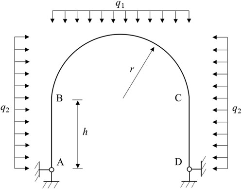
FIGURE 1. Mechanical model of the U-steel.
In the Eqs. 1, 2, γ is the average bulk density of the overlying surrounding rock, H is buried depth, and λ is the lateral pressure coefficient.
2.2 Solution of constraint reaction force
The mechanical model of the plane rigid frame is a statically indeterminate structure. In Figure 1, both ends A and D are fixed hinges. The principle of force method is adopted to solve the problem. Supposing the horizontal constraint of point D is released, and the force F is used instead, thus the basic statically system with hinged end A and rolling support end D is obtained. The basic structural system after removing redundant constraints is shown in Figure 2. The displacement of the point D is calculated by the principle of force method. Assuming that a right horizontal unit force is applied to the point D, then the equation of axial force and the bending moment of rigid frame can be calculated. Actually, the end D is a fixed hinge support, the horizontal displacement of point D is zero, and the calculation formula is:
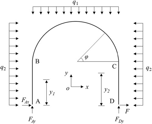
FIGURE 2. Calculation model of internal force equation under external load.
From the static equilibrium equation of Eq. 3, the force F can be resolved:
The bending moment equation of AB, CD and BC sections of plane rigid frame are listed in Eqs. 8–10:
Where φ is the angle between the arbitrary section of BC segment and the section of point C.
2.3 Determination of dangerous section position
The sections AB and CD of plane rigid frame are symmetrical structures, and the positions of dangerous sections are also symmetrically distributed. Therefore, the AB section is used as the analysis object to determine the dangerous section of the U-steel support. Taking the uniform load (q1 = q2 ≠ 0) of the support as an example. The basic mechanical parameters of U-steel support that used in the tunnel cavern are listed in Table 1. The above mechanical parameters are substituted into Eqs. 4–7, then the force F can be solved in Eq. 11:
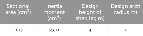
TABLE 1. The basic mechanical parameters of U-steel support.
According to the bending moment equation of the plane rigid frame AB section, the bending moment curve is a quadratic parabola. Differentiating the bending moment equation of the plane rigid frame AB section, as shown in Eq. 12:
The location of the dangerous section of the AB section of the U-steel support is calculated in Eq. 13:
According to the condition of q1 = q2 ≠ 0, the potential dangerous section of AB section is 4.47 m away from the foot of shed leg. It can be judged from Eq. 10 that the dangerous section of the BC section is the middle of the arch. In practical engineering, the sectional area, inertia moment and cavern size are relatively constant. The change of dangerous section position of support is related to the lateral pressure coefficient, that is, the force transferred between support and surrounding rock, which is manifested in the difference of contact force between support and surrounding rock.
3 Case study
3.1 Engineering background
The excavation size of left and right bank underground cavern groups of the Baihetan Hydropower Station are huge, among them the layout of designed right caverns is indicated in Figure 3. The powerhouse is divided into ten layers along the elevation, and the cavern is excavated by the traditional D&B method. The designed excavation and blasting scheme of the powerhouse is demonstrated in Figure 4.

FIGURE 3. The layout of designed right underground cavern groups.
FIGURE 4. Blasting excavation scheme of the underground powerhouse.
3.2 In-situ seismic monitoring experiment
The excavation size of underground cavern group is large, and the cavern group is in high stress environment, which means it is easy to induce the failure of the surrounding rock. Due to the unfavourable multi-face empty environment of the busbar tunnel, the disturbance degree of blast excavation unloading on surrounding rock near the intersecting cavern is obviously greater than that of single cavern. In order to effectively inhibit the internal fracture evolution or macroscopic deformation of surrounding rock of busbar tunnel, the reinforcement measures such as rockbolt and U-steel support scheme are often used. The schematic diagram of the U-steel support of the busbar tunnel is shown in Figure 5.
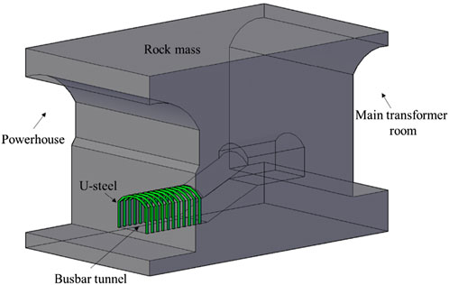
FIGURE 5. Schematic diagram of the U-steel support of the busbar tunnel.
The busbar tunnel intersects with the powerhouse, and the U-steel supports of the busbar tunnel are inevitably be impacted by the blasting excavation of the powerhouse. In order to study the dynamic response characteristics of the U-steel support under blast excavation load, a microseismic monitoring test was carried out during the excavation of the cavern. The 11# intersecting cavern area is selected as the research object. Three-dimensional layout of microseismic sensor network of underground cavern is described in Figure 6. There are three monitoring sections surrounding the research area. Two microseismic sensors are installed on each section, and the distance between adjacent monitoring section is 30 m. The adopted microseismic sensor in underground cavern is the uniaxial geophone. The bandwidth and sensitivity of the geophones used are 7–2000 Hz and 100 V/m/s, respectively.
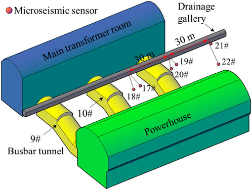
FIGURE 6. Three-dimensional layout of microseismic sensor network of underground cavern.
3.3 Vibration response of the support structure
3.3.1 Blast signal characteristic
The forced vibration of U-steel support structure is excited by blast load. Studying the vibration signal excited by blast load is helpful to understand the dynamic characteristics and mechanical mechanism of support structure. The representative waveform of the blast signal received by the MS sensor is shown in Figure 7. Millisecond blast technology is used in the field construction of underground cavern, resulting in multiple persistence of the excited blast spectrum, that is, a single blast spectrum contains multiple similar subwaveforms.
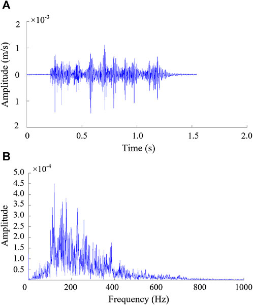
FIGURE 7. Waveform characteristics of blast signal: (A) amplitude-time curve, (B) amplitude-frequency curve.
3.3.2 Evolution mechanism of MS events
In the process of blast excavation of underground cavern, the blast shock wave is not directly applied to the support structure, but is transmitted to the support structure through the rock mass medium. Therefore, the fracture process of rock mass around the support structure can also reflect the vibration characteristics of the support structure. When rock breaks, energy is released in the form of an elastic wave. Theoretically, any fracture will produce an elastic wave accompanied by a slight vibration. If the vibration signal generated by the rock fracture triggers the sensor, then the rock fracture is recorded as a microseismic event. The spatial evolution of microseismic events induced by blast excavation is displayed in Figure 8. In the diagram, the color of the ball represents the moment magnitude. The brighter the color, the larger the magnitude. Moment magnitude is a source parameter that uses the seismic moment to describe the magnitude of an earthquake rupture. The size of the ball represents the radiated microseismic energy, and the larger the radius of the ball, the greater the released microseismic energy. According to the vibration response degree of support structure to on-site blast excavation, the spatial evolution of microseismic events can be divided into three stages: 1) Crack initiation period (Figure 8A). There are a few microseismic events induced by blast excavation. The spatial evolution shows that the micro-fracture initiates at the arch shoulder of the small chainage side of busbar tunnel. 2) Crack propagation period (Figure 8B). A small number of large magnitude events are induced by blast excavation, accompanied by a large number of small magnitude events, which indicates that primary fracture propagation or new fracture initiation occurs in rock mass under the action of tangential concentrated stress. 3) Crack cluster period (Figure 8C). The rock mass enters the active period of deformation and fracture influenced by the strong blast load. At this stage, the microseismic events occur frequently, and the cumulative microseismic energy increases.
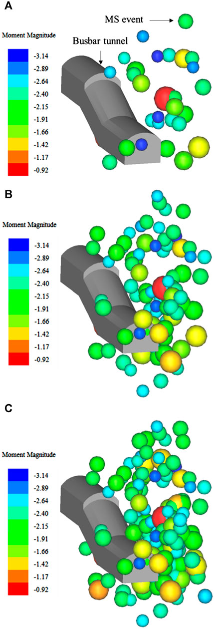
FIGURE 8. Spatial evolution of microseismic events in rock mass induced by blast load. (A) Crack initiation period, (B) crack propagation period, and (C) crack cluster period.
In addition, blast load is the important factor causing the damage and deterioration of surrounding rock of the busbar tunnel. It is found that the microseismic events of large magnitude near the working face often occur within a few hours after blast. Blast load is equivalent to the transient convergence of rock mass after excavation, providing favorable conditions for deformation and failure of U-steel support structure. Therefore, the excavation method of short footage and discontinuous blasting should be adopted when the working face advances to the vicinity of the intersecting cavern.
The on-site survey found that the concrete spray layer of busbar tunnel peeled off and the U-steel structure was partially extruded and deformed. The failure of U-steel is the extrusion deformation under compressive stress. The damage location of U-steel support structure is consistent with the cluster area of microseismic events, as shown in Figure 9. The cluster nucleation of microseismic events indicates that the internal fracture of surrounding rock in this area is serious, and the deformation and failure of hard brittle surrounding rock first occurs in the stress concentration area. The failure of the U-steel support is also closely related to the redistribution stress after blast excavation.
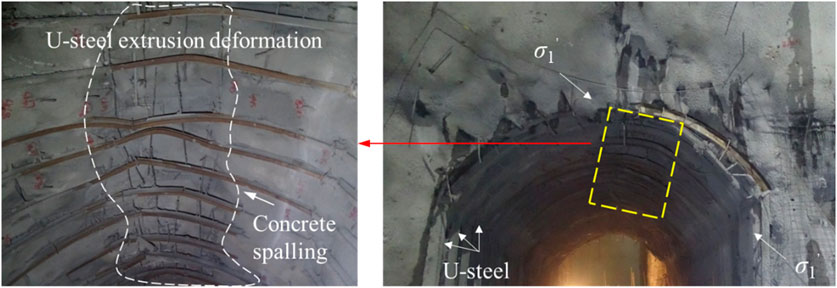
FIGURE 9. Blast-induced local failure of U-steel support structure.
3.3.3 Apparent stress of microseismic events
Apparent stress can effectively measure the magnitude of dynamic stress release in the seismic source, which is a microseismic parameter independent of the source model. The calculation formula of apparent stress is:
In the formula, μ is the shear modulus, E is the radiated microseismic energy, and M is the seismic moment.
The relationship between apparent stress and seismic moment of microseismic events is illustrated in Figure 10. The color of the ball in the figure represents the microseismic energy of the microseismic event. The lighter the color, the smaller the energy released. The size of the ball represents the moment magnitude of the microseismic event. The larger the radius of the ball, the larger the magnitude of the event. The apparent stress and seismic moment relation is approximately power-law, and so a linear fit is used in the log-log plot. The instability dynamic process of the structure can be expressed by Eq. 14, which depends on the stiffness ratio of the unstable rock to the surrounding rock mass.
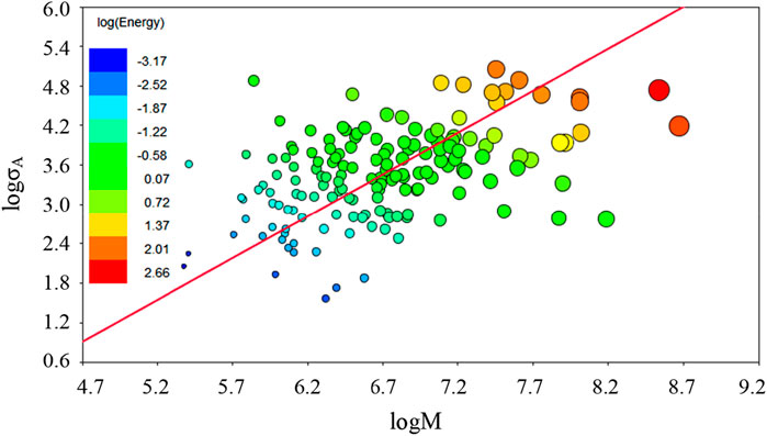
FIGURE 10. Relationship between apparent stress and seismic moment.
In general, the greater the degree of stress concentration, the greater the elastic strain energy released when the rock mass breaks. The magnitude of energy release can be reflected by the source parameter of apparent stress. The blast-induced cloud diagram of apparent stress of microseismic events is shown in Figure 11. As shown in the figure, the apparent stress is concentrated in the contour of busbar tunnel, especially in the arch shoulder of the small chainage and the arch foot of the large chainage. The apparent stress concentration indicates that the stress level and the risk of fracture of the support structure are high. In addition, the busbar tunnel is in an unfavorable multi-face empty and multi-faceted unloading stress environment, which further aggravates the risk of failure to the U-steel support structure.
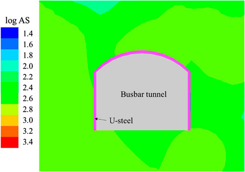
FIGURE 11. Apparent stress (AS) cloud of microseismic events induced by blast load.
4 Discussion
The instability of U-steel structure induced by blast loading is the main cause of extrusion deformation of the support. To ensure the safety and stability of the supporting load-bearing structure, the impact stress can be decreased by reducing the excavation footage and blasting charge. The structural stability of the support structure is also an important factor affecting the deformation and instability of U-steel support. In reality, the area between the U-steel and the surrounding rock is usually unevenly distributed, influenced by the blasting technique, lithology and structural plane, resulting in poor mechanical interaction between the rock and the support structure. In addition, the unfavourable interaction relationship significantly reduces the overall load-bearing capacity of the U-steel structure, resulting in structural instability of the support. The specific form of structural instability failure is closely related to the region of uneven air gaps distribution behind the U-steel. For example, the pinnacle shaped failure of U-steel when the air gap is distributed in the top arch (Figure 12A), and the flat-top shaped failure of U-steel when the air gaps are distributed in the spandrel of cavern (Figure 12B).
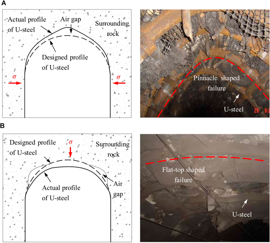
FIGURE 12. Schematic diagram of structural instability failure of U-steel support: (A) pinnacle shaped failure, (B) flat-top shaped failure.
Based on the above-mentioned typical unstable section and the failure characteristics of U-steel support, a synergetic reinforcement scheme is proposed. The designed synergetic reinforcement scheme of structure with support and surrounding rock is shown in Figure 13. The synergetic reinforcement is a method in which the U-steel, the back wall filling and the pre-stressed anchor cable are coupled together. The synergetic reinforcement compensates the bearing capacity and structural stability of the support by the anchor cable at a reasonable position, which can improve the overall bearing capacity and structural stability of the U-steel support. At the same time, the U-steel support provides a good surface protection component for the anchor cable, and improves the anchoring performance of the anchor cable. In essence, the main purpose of reinforcement is the mobilisation of the self-supporting capacity of the surrounding rock to the greatest extent possible. After the installation of U-steel and the filling behind the wall, the I-steel coupling joist is used to install the prestressed anchor cable at the dangerous section. On the one hand, the scheme can effectively realize the efficient transmission of the prestress, and provide certain structural compensation force to the unstable section position. The stress of the potential failure section of the support structure is greatly reduced after adopted the synergetic reinforcement scheme. On the other hand, the synergetic reinforcement measure can promote the uniform distribution of the external load of the support, thereby improving the overall bearing performance of the support structure.
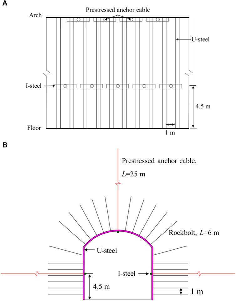
FIGURE 13. Synergetic reinforcement scheme of U-steel and prestressed cable: (A) lateral view, (B) front view of support structure.
5 Conclusion
An in-situ microseismic monitoring system is established in the cavern of the Baihetan Hydropower Station, and the impact of blasting on the U-steel support structure is investigated. The dynamic response and failure process of the U-steel support under blast loading are obtained by microseismic monitoring experiment and theoretical analysis. The monitoring results show that the forced vibration of the U-steel support structure is excited by the blast load. The concrete spray layer of the busbar tunnel is delaminated and the U-steel structure is partially extruded and deformed under the blast load. Furthermore, the location of the damage to the U-steel support structure is consistent with the area of the cluster of microseismic events. The apparent stress is concentrated in the contour of the busbar tunnel, particularly in the arch shoulder of the small chainage and the arch foot of the large chainage.
In addition to the effects of blast loading, the structural stability of the support is an important factor in the deformation and instability of the U-steel support. Therefore, the synergetic reinforcement scheme is proposed to inhibit the deterioration of the surrounding rock. The results showed that the designed synergetic reinforcement scheme could provide a certain structural compensating force to the unstable section position, and improve the overall bearing performance of the U-steel support structure.
Data availability statement
The original contributions presented in the study are included in the article/Supplementary material, further inquiries can be directed to the corresponding authors.
Author contributions
J-SZ: Funding acquisition, Methodology, Writing–original draft, Data curation, Resources, Supervision. J-HY: Formal Analysis, Supervision, Writing–review and editing. P-XL: Formal Analysis, Investigation, Methodology, Writing–review and editing. X-HZ: Validation, Writing–review and editing. C-FC: Methodology, Writing–review and editing. J-CZ: Methodology, Writing–review and editing.
Funding
The author(s) declare financial support was received for the research, authorship, and/or publication of this article. This research is supported by the National Natural Science Foundation of China (52209132, 52209120), the CRSRI Open Research Program (Program SN: CKWV20231173/KY), and China Postdoctoral Science Foundation (2023M733317).
Acknowledgments
The authors would like to thank Bing-Rui Chen and Quan Jiang for their help with the MS monitoring experiment.
Conflict of interest
J-CZ is employed by the PowerChina Huadong Engineering Corporation Limited.
The remaining authors declare that the research was conducted in the absence of any commercial or financial relationships that could be construed as a potential conflict of interest.
Publisher’s note
All claims expressed in this article are solely those of the authors and do not necessarily represent those of their affiliated organizations, or those of the publisher, the editors and the reviewers. Any product that may be evaluated in this article, or claim that may be made by its manufacturer, is not guaranteed or endorsed by the publisher.
References
Barla, G., Bonini, M., and Semeraro, M. (2011). Analysis of the behaviour of a yield-control support system in squeezing rock. Tunn. Undergr. Sp. Tech. 26 (1), 146–154. doi:10.1016/j.tust.2010.08.001
Brady, B. H. G., and Brown, E. T. (2005). Rock mechanics for underground mining. New York, NY, USA: Kluwer Academic Publishers.
Chen, B.-R., Feng, X.-T., Li, Q.-P., Luo, R.-Z., and Li, S. (2015). Rock burst intensity classification based on the radiated energy with damage intensity at jinping II hydropower station, China. Rock Mech. Rock. Eng. 48 (1), 289–303. doi:10.1007/s00603-013-0524-2
Chen, B.-R., Wang, X., Zhu, X., Wang, Q., and Xie, H. (2023). Real-time arrival picking of rock microfracture signals based on convolutional-recurrent neural network and its engineering application. J. Rock Mech. Geotech. online. doi:10.1016/j.jrmge.2023.07.003
Chen, S.-j., Feng, F., Wang, Y.-j., Li, D.-y., Huang, W.-p., Zhao, X.-d., et al. (2020). Tunnel failure in hard rock with multiple weak planes due to excavation unloading of in-situ stress. J. Cent. South. Univ. 27 (10), 2864–2882. doi:10.1007/s11771-020-4515-7
Cheng, C., Jia, P., Ni, P., Wang, Y., Zhao, W., Guan, Y., et al. (2023a). Upper bound analysis of longitudinally inclined EPB shield tunnel face stability in dense sand strata. Transp. Geotech. 41, 101031. doi:10.1016/j.trgeo.2023.101031
Cheng, C., Yang, H., Jia, P., Ni, P., Shi, P., Ma, P., et al. (2023b). Face stability of shallowly buried large-section EPB box jacking crossing the beijing-hangzhou grand canal. Tunn. Undergr. Sp. Tech. 138, 105200. doi:10.1016/j.tust.2023.105200
Cui, X. Z., Li, J., Yang, G. D., Fei, W., Ding, S., and Fan, Y. (2023). Spatial migration and distribution of suspended particles in saturated sand layer under the impact of temperature. Hydrol. Process. 37 (2), e14833. doi:10.1002/hyp.14833
Dai, F., Li, B., Xu, N. W., Fan, Y. L., and Zhang, C. Q. (2016). Deformation forecasting and stability analysis of large-scale underground powerhouse caverns from microseismic monitoring. Int. J. Rock. Mech. Min. 86, 269–281. doi:10.1016/j.ijrmms.2016.05.001
Dong, L.-j., Tang, Z., Li, X.-b., Chen, Y.-c., and Xue, J.-c. (2020). Discrimination of mining microseismic events and blasts using convolutional neural networks and original waveform. J. Cent. South. Univ. 27, 3078–3089. doi:10.1007/s11771-020-4530-8
Dong, L.-J., Wesseloo, J., Potvin, Y., and Li, X.-B. (2016). Discriminant models of blasts and seismic events in mine seismology. Int. J. Rock. Mech. Min. 86, 282–291. doi:10.1016/j.ijrmms.2016.04.021
Feng, F., Chen, S., Han, Z., Golsanami, N., Liang, P., and Xie, Z. (2023). Influence of moisture content and intermediate principal stress on cracking behavior of sandstone subjected to true triaxial unloading conditions. Eng. Fract. Mech. 284, 109265. doi:10.1016/j.engfracmech.2023.109265
Feng, F., Chen, S., Wang, Y., Huang, W., and Han, Z. (2021). Cracking mechanism and strength criteria evaluation of granite affected by intermediate principal stresses subjected to unloading stress state. Int. J. Rock. Mech. Min. 143, 104783. doi:10.1016/j.ijrmms.2021.104783
Feng, X. T., Pei, S. F., Jiang, Q., Zhou, Y. Y., Li, S. J., and Yao, Z. B. (2017). Deep fracturing of the hard rock surrounding a large underground cavern subjected to high geostress: in situ observation and mechanism analysis. Rock Mech. Rock. Eng. 50 (8), 2155–2175. doi:10.1007/s00603-017-1220-4
Gong, F.-q., Luo, Y., Li, X.-b., Si, X.-f., and Tao, M. (2018). Experimental simulation investigation on rockburst induced by spalling failure in deep circular tunnels. Tunn. Undergr. Sp. Tech. 81, 413–427. doi:10.1016/j.tust.2018.07.035
Guo, H., Sun, Q., Feng, G., Li, S., and Xiao, Y. (2023). In-situ observations of damage-fracture evolution in surrounding rock upon unloading in 2400-m-deep tunnels. Int. J. Min. Sci. Techno. 33 (4), 437–446. doi:10.1016/j.ijmst.2022.11.008
Jiang, Q., Feng, X.-T., Cui, J., and Li, S.-J. (2015). Failure mechanism of unbonded prestressed thru-anchor cables: in situ investigation in large underground caverns. Rock Mech. Rock. Eng. 48 (2), 873–878. doi:10.1007/s00603-014-0574-0
Kaiser, P. K., and Cai, M. (2012). Design of rock support system under rockburst condition. J. Rock Mech. Geotech. 4, 215–227. doi:10.3724/SP.J.1235.2012.00215
Laura, B., and Martin, H. (2017). Identification of stress change within a rock mass through apparent stress of local seismic events. Rock Mech. Rock. Eng. 50, 81–88. doi:10.1007/s00603-016-1092-z
Li, A., Dai, F., Wu, W., Liu, Y., Liu, K., and Wang, K. (2022). Deformation characteristics of sidewall and anchorage mechanisms of prestressed cables in layered rock strata dipping steeply into the inner space of underground powerhouse cavern. Int. J. Rock. Mech. Min. Sci. 159, 105234. doi:10.1016/j.ijrmms.2022.105234
Li, B., Xu, N., Xiao, P., Xia, Y., Zhou, X., Gu, G., et al. (2023a). Microseismic monitoring and forecasting of dynamic disasters in underground hydropower projects in southwest China: a review. J. Rock Mech. Geotech. 15, 2158–2177. doi:10.1016/j.jrmge.2022.10.017
Li, C.-C., and Doucet, C. (2012). Performance of D-bolts under dynamic loading. Rock Mech. Rock. Eng. 45, 193–204. doi:10.1007/s00603-011-0202-1
Li, P. X., Chen, B. R., Xiao, Y. X., Feng, G. L., Zhou, Y. Y., and Zhao, J. S. (2023b). Rockburst and microseismic activity in a lagging tunnel as the spacing between twin tbm excavated tunnels changes: a case from the neelum-jhelum hydropower project. Tunn. Undergr. Sp. Tech. 132, 104884. doi:10.1016/j.tust.2022.104884
Li, Z.-W., Huang, C.-Y., Wang, H.-X., Xing, S.-C., Long, M.-C., and Liu, Y. (2023c). Determination of heat transfer representative element volume and three-dimensional thermal conductivity tensor of fractured rock masses. Int. J. Rock. Mech. Min. Sci. 170, 105528. doi:10.1016/j.ijrmms.2023.105528
Li, Z.-W., Long, M.-C., Xu, P., Huang, C.-Y., and Wang, Y.-S. (2023d). Thermal contact resistance of granite joints under normal stress. Rock Mech. Rock. Eng. online 56, 8317–8338. doi:10.1007/s00603-023-03450-9
Liu, G. F., Ran, G., Li, Z., Duan, S., Su, G., Yan, C., et al. (2023). An insight into the effect of primary hidden microfissures on mechanical behaviors and failure characteristics of brittle basalt. Theor. Appl. Fract. Mec. online 128, 104138. doi:10.1016/j.tafmec.2023.104138
Liu, J.-p., Si, Y.-t., Wei, D.-c., Shi, H.-x., and Wang, R. (2021). Developments and prospects of microseismic monitoring technology in underground metal mines in China. J. Cent. South. Univ. 28, 3074–3098. doi:10.1007/s11771-021-4839-y
Lu, B., Jia, P., Zhao, W., Zheng, Q., Du, X., and Tang, X. (2023). Longitudinal mechanical force mechanism and structural design of steel tube slab structures. Tunn. Undergr. Sp. Tech. 132, 104883. doi:10.1016/j.tust.2022.104883
Ma, C., Jiang, Y., and Li, T. (2019). Gravitational search algorithm for microseismic source location in tunneling: performance analysis and engineering case study. Rock Mech. Rock. Eng. 52, 3999–4016. doi:10.1007/s00603-019-01809-5
Ma, K., Tang, C.-a., Xu, N.-w., Liu, F., and Xu, J.-w. (2013). Failure precursor of surrounding rock mass around cross tunnel in high-steep rock slope. J. Cent. South. Univ. 20, 207–217. doi:10.1007/s11771-013-1478-y
Ma, T.-H., Tang, C.-A., Tang, S.-B., Kuang, L., Yu, Q., Kong, D.-Q., et al. (2018). Rockburst mechanism and prediction based on microseismic monitoring. Int. J. Rock. Mech. Min. Sci. 110, 177–188. doi:10.1016/j.ijrmms.2018.07.016
Mei, S., Feng, X.-T., Li, Z., Yang, C., and Gao, J. (2023). Experimental study on the failure process of fault rock bursts in tunnels based on a 3D-printed large-scale physical model. Int. J. Geomech. 23, 04023139. doi:10.1061/IJGNAI.GMENG-8510
Wang, H., Zheng, P.-q., Zhao, W.-j., and Tian, H.-m. (2018). Application of a combined supporting technology with U-shaped steel support and anchor-grouting to surrounding soft rock reinforcement in roadway. J. Cent. South. Univ. 25, 1240–1250. doi:10.1007/s11771-018-3821-9
Wang, Q., Ye, H., Li, N., Chi, X., Xie, W., Chen, D., et al. (2021). A study of support characteristics of collaborative reinforce system of U-steel support and anchored cable for roadway under high dynamic stress. Geofluids 2021, 1–12. doi:10.1155/2021/9881280
Wong, L. N. Y., Fang, Q., and Zhang, D. (2013). Mechanical analysis of circular tunnels supported by steel sets embedded in primary linings. Tunn. Undergr. Sp. Tech. 37, 80–88. doi:10.1016/j.tust.2013.03.011
Wu, Y., Gao, F., Chen, J., and He, J. (2019). Experimental study on the performance of rock bolts in coal burst-prone mines. Rock Mech. Rock. Eng. 52, 3959–3970. doi:10.1007/s00603-019-01794-9
Xia, K. Z., Chen, C., Liu, X., Liu, X., Yuan, J., and Dang, S. (2023a). Assessing the stability of high-level pillars in deeply-buried metal mines stabilized using cemented backfill. Int. J. Rock. Mech. Min. Sci. 170, 105489. doi:10.1016/j.ijrmms.2023.105489
Xia, Y. L., Xu, D. P., Qiu, S. L., Liu, X. Y., Huang, X., and Li, Z. G. (2023b). Experimental study on mechanical properties of deeply buried granite during layered excavation of large underground caverns. Rock Mech. Rock. Eng. 56 (7), 4757–4778. doi:10.1007/s00603-023-03304-4
Xu, D., Liu, X., Jiang, Q., Li, S., Zhou, Y., Qiu, S., et al. (2022). A local homogenization approach for simulating the reinforcement effect of the fully grouted bolt in deep underground openings. Int. J. Min. Sci. Techno. 32, 247–259. doi:10.1016/j.ijmst.2022.01.003
Xu, H. S., Li, S. J., Xu, D. P., Huang, X., Zheng, M., He, J., et al. (2023a). Numerical back analysis method of three-dimensional in situ stress fields considering complex surface topography and variable collinearity. Int. J. Rock Mech. Min. Sci. 170, 105474. doi:10.1016/j.ijrmms.2023.105474
Xu, H. S., Xu, D. P., Li, S. J., Zheng, M., Huang, X., Chen, B., et al. (2023b). Stress tensor similarity index based on euclidean distance for numerical back analysis of in situ stress fields. Comput. Geotech. 159, 105457. doi:10.1016/j.compgeo.2023.105457
Xu, N., Wu, J., Dai, F., Fan, Y., Li, T., and Li, B. (2018). Comprehensive evaluation of the stability of the left-bank slope at the baihetan hydropower station in southwest China. B. Eng. Geol. Environ. 77, 1567–1588. doi:10.1007/s10064-017-1018-3
Yang, G., Fan, Y., Wang, G., Cui, X., Li, Q., and Leng, Z. (2023). Experimental and numerical investigation on dynamic behavior of RC orifice targets subjected to underwater explosions. Eng. Struct. 279, 115541. doi:10.1016/j.engstruct.2022.115541
Yang, G., Wang, G., Fan, Y., Deng, K., Lu, W., and Zhao, J. (2021). Dynamic response and performance of submarine tunnel subjected to surface explosions. Mar. Struct. 80, 103091. doi:10.1016/j.marstruc.2021.103091
Zhao, J.-S., Chen, B.-R., Jiang, Q., Lu, J.-F., Hao, X.-J., Pei, S.-F., et al. (2022a). Microseismic monitoring of rock mass fracture response to blasting excavation of large underground caverns under high geostress. Rock Mech. Rock. Eng. 55, 733–750. doi:10.1007/s00603-021-02709-3
Zhao, J.-S., Duan, S.-Q., Chen, B.-R., Li, L., He, B.-G., Li, P.-X., et al. (2024). Failure mechanism of rock masses with complex geological conditions in a large underground cavern: a case study. Soil. Dyn. Earthq. Eng. 177, 108439. doi:10.1016/j.soildyn.2023.108439
Zhao, J.-S., Jiang, Q., Lu, J.-F., Chen, B.-R., Pei, S.-F., and Wang, Z.-L. (2022b). Rock fracturing observation based on microseismic monitoring and borehole imaging: in situ investigation in a large underground cavern under high geostress. Tunn. Undergr. Sp. Tech. 126, 104549. doi:10.1016/j.tust.2022.104549
Zhao, J.-s., Jiang, Q., Pei, S.-f., Chen, B.-r., Xu, D.-p., and Song, L.-b. (2023). Microseismicity and focal mechanism of blasting-induced block falling of intersecting chamber of large underground cavern under high geostress. J. Cent. South. Univ. 30, 542–554. doi:10.1007/s11771-023-5259-y
Zhao, Y., Liu, N., Zheng, X., and Zhang, N. (2015). Mechanical model for controlling floor heave in deep roadways with U-shaped steel closed support. Int. J. Min. Sci. Techno. 25, 713–720. doi:10.1016/j.ijmst.2015.07.003
Zheng, Z., Li, R., and Zhang, Q. (2023a). A novel anisotropic deterioration mechanical model for rock ductile-brittle failure under 3D high-stress and its application. Comput. Geotech. 162, 105665. doi:10.1016/j.compgeo.2023.105665
Keywords: underground cavern, u-steel support, blast load, microseismic monitoring, structural performance
Citation: Zhao J-S, Yang J-H, Li P-X, Zhu X-H, Chen C-F and Zhang J-C (2024) Mechanical performance and failure mechanism of U-steel support structure under blast loading. Front. Earth Sci. 11:1314034. doi: 10.3389/feart.2023.1314034
Received: 10 October 2023; Accepted: 20 November 2023;
Published: 02 February 2024.
Edited by:
Pengjiao Jia, Soochow University, ChinaReviewed by:
Ang Li, Chang’an University, ChinaJinjin Ge, Anhui University of Science and Technology, China
Copyright © 2024 Zhao, Yang, Li, Zhu, Chen and Zhang. This is an open-access article distributed under the terms of the Creative Commons Attribution License (CC BY). The use, distribution or reproduction in other forums is permitted, provided the original author(s) and the copyright owner(s) are credited and that the original publication in this journal is cited, in accordance with accepted academic practice. No use, distribution or reproduction is permitted which does not comply with these terms.
*Correspondence: Peng-Xiang Li, lipengxiangsd@163.com; Xin-Hao Zhu, zhuxinhao01@163.com