Experimental study on characteristics of flame propagation and pressure development evolution during methane-air explosion in different pipeline structures
 Rongjun Si
 Leilin Zhang2*
  Yihui Niu
 Zichao Huang
- 1Fire and Explosion Prevention Research Branch, China Coal Technology and Engineering Group Chongqing Research Institute, Chongqing, China
- 2Engineering Technology Research Centre for Safe and Efficient Coal Mining, Anhui University of Science and Technology, Huainan, China
- 3College of Safety Engineering, Chongqing University of Science and Technology, Chongqing, China
A gas explosion experimental system based on a piece of 15 m-long and φ180 semi-closed wide open steel pipe was constructed. An explosion experimental study on straight pipelines and pipeline structures with different angles (45°, 90°, and 135°) was conducted. Research results demonstrated that before the turn, flame propagation speed and flame sustaining time in different pipeline structures were consistent. With the increase of the distance away from the ignition source, the flame propagation velocity increases and the flame sustaining time decreases; at the turning point, the flame velocity suddenly decreases and the flame duration increases obviously. Meanwhile, the peak value of overpressure on the lateral wall of the turning corner is greater than that on the inner wall. Among the three different angles, the peak value of overpressure on the lateral wall of 135° bend is the highest. Different pipeline structures have great influence on gas explosion overpressure and flame propagation speed. These research conclusions provide theoretical references for gas explosion resistance in coal mines.
1 Introduction
Gas and coal dust, which run through the whole coal mine production activity, are one of the main natural disasters in coal mines. When the gas concentration and oxygen concentration reach a certain limit and a high-temperature heat source is encountered, gas or coal dust explosion occurs, which not only destroys the underground ventilation network and endangers the safety of life and property but also causes a secondary explosion and brings devastating disasters to the mine (Huang et al., 2023). Therefore, it is significant to understand the mechanism of shock wave propagation after methane explosion in order to reduce the damage of gas explosion in coal mine roadway.
Due to the limited conditions of gas explosion test conducted in coal mine roadway, many researchers have conducted pipeline and small-scale container tests either through numerical simulation or in the laboratory. The laminar deflagration of CH4-air mixture at various initial pressures of 50–200 kPa was studied by Mitu in two closed concentrated igniting vessels (Mitu et al., 2017). Cui et al. (2018) analyzed the effects of pressure and temperature on the duration of combustion in the initial temperature range of 123–273K. Zhai et al., 2008 found in square straight tubes that turbulent combustion and flame propagation acceleration occur when the cross section of the pipe suddenly expands or shrinks. Ajrash et al. (2017) studied the effects of different concentrations of methane and reaction length on pressure wave and flame characteristics in a 30-m long, straight and large-scale detonation tube. Jiang and Su, 2016 found that the peak value of shock wave overpressure and the velocity of flame propagation increased with the increase of distance in a semi-closed straight tube, and the results were verified by numerical simulation. Zhu et al. (2017) have studied the flame propagation velocity in the bifurcated pipeline. It is found that the velocity of the flame decreases obviously in the bifurcation part, but the flame velocity is higher after the bifurcation. Sulaiman et al. (2014) has found that the existence of a 90° turning pipe can elevate flame propagation velocity by approximately twice by using the FLACS numerical simulation software. Frolov et al. (2007) has studied the process of deflagration to detonation in U-shaped structural pipe. However, there is a lack of research on the intensity of the gas explosion and flame acceleration mechanism in the different structures of the pipeline at the turn or bifurcation.
In the study on the propagation law of gas explosion, factors such as gas volume dose, pipeline cross-sectional area, and obstacle distribution greatly influence on the overpressure evolution laws and flame propagation characteristics of shock wave (Huang et al., 2020; Niu et al., 2021; Yan et al., 2022; Jia et al., 2023; Niu et al., 2020) established a set of experimental system in pipeline network to test the propagation characteristics of shock waves in complex areas and found that there is a pressure increasing area in the corner branch of the shock wave, but it is not affected by the flame. Zhu et al. (2021) investigated the overpressure evolution law and the flame propagation process when a gas explosion occurs in U- shaped longwall coalface and H-shaped crosscut by numerical simulation, and found that a very high reflected pressure exists close to the corner but decays very fast in the free spaces. Zhang et al. (2021) conducted pipeline gas explosion experiments at different turning angles and found that the peak overpressure attenuation rate of the shock wave increased with the increase of the pipeline turning angle. The flame propagation speed first increased and then decreased, and rapidly increased after passing through the curved pipeline. Wang et al. (2018) studied the attenuation law of gas explosion in experimental tunnel with a length of 800 m and an inclination angle of 24°, and found that as the propagation distance increased, the explosion pressure did not decay linearly, but fluctuated along the tunnel, and the flame propagation speed first increased and then decreased throughout the entire explosion process. The current research is mainly focused on the explosion pressure and flame propagation speed, while relatively little research on flame sustainable time.
There are differences in the propagation characteristics of gas explosions in pipelines with different structures. Previous work focused on the use of straight or 90° curved tubes, and less research on sharp or obtuse angles. In particular, their results do not involve the investigation of the flame velocity, flame duration and the peak value of overpressure of the inner and outer wall of the explosion shock wave in the turning region under the condition of partial filling of gas in the pipeline. However, the structure of the mine roadway is complex and the different angle of turning will interfere with the propagation of shock wave, which may occur in different situations. If the underground gas is still treated according to the propagation characteristics of gas explosions in straight or 90° curved pipelines, selecting explosion prevention measures will make these explosion prevention devices ineffective. Therefore, an experimental system for gas explosion of open steel pipe is constructed, which focuses on the flame propagation law and pressure development characteristics of shock wave in different pipe structures at the bend.
2 Establishment of the experimental system
Figure 1 shows the gas explosion experimental apparatus. This equipment was composed of four subsystems: pipeline, ignition, distribution, and data collection. The pipeline subsystem used the 15 m-long and φ180-wide pipeline. The ignition end was closed and the other end was open. A plastic film is placed 10.5 m from the ignition source to seal the 10.5 m long pipe so that the gas is filled at this distance. The ignition subsystem controlled the ignition electrode in the middle of the flange at the front end of the pipeline through the ignition device. The electric spark with a 10 J ignition energy was applied for ignition. The distribution subsystem consisted of an air compressor, vacuum pump, and air and gas cylinder. The air compressor offered at least 30 min of high-pressure ventilation to the pipeline subsystem. The vacuum pump vacuumed the premixed methane–air region. The methane gas concentration was calculated in accordance with Dalton’s law of partial pressure. The inlet quantities of methane and air were controlled accurately by the precise vacuum pressure meter to assure that the methane concentration in each experiment was approximately 10%. Subsequently, at least 20 min of gas circulation was implemented through the circulating pump to ensure a uniform and complete mixture of methane and air. Data acquisition subsystem includes flame and pressure sensor, high-frequency data collector, and working machine. The pressure sensor model is CYG1401, with a measuring range of 0 ∼ 3Mpa and the accuracy is 0.5% FS, the flame sensor is a CKG100 photoelectric type and an accuracy of 0.1% FS. The collected signals were transmitted to the working machine through a 32-path high-frequency data collector.
FIGURE 1. Schematic of experimental apparatus.
Figure 2 displays the flame and pressure sensor distributions in straight and turning pipelines. Eight flame sensors (F1-F8) and eight pressure sensors (P1-P8) are respectively arranged along the center line above the pipe. For the turning piping, the pressure sensor P4 is arranged outside the corner, and the pressure sensor P5 is arranged inside the corner. Table 1 and Table 2 presents the distances of different flame and pressure sensors to the ignition source. Three tests were conducted under each experimental condition, and the mean was used as the experimental result.
FIGURE 2. Layout of fiame transducers in the pipe. (A) Straight pipe; (B) 45° pipe; (C) 90° pipe; (D) 135° pipe.

TABLE 1. Distance of each flame sensor from the ignition source (m).

TABLE 2. Distance of each pressure sensor from the ignition source (m).
3 Experimental results and discussions
3.1 Analysis of flame propagation speed in different pipeline structures
Figure 3 shows the variation trend of flame arrive time in different pipelines. As the increase of distance away from the ignition source, the flame arrival time tends to increase gradually.
FIGURE 3. Flame arrive time of different pipeline structures.
In this experiment, the flame propagation speed was calculated by using Eq. 1:
where v is the flame propagation speed and xn denotes the distance between the flame sensors n + 1 and n. Tn+1 and tn represent the moments when the flame front ends n + 1 and n arrive at the flame sensor, respectively.
Figure 4 shows the variation trend of flame speeds in different pipelines. Table 3 shows the test results of flame propagation speed after the calculation. We can see the explosive shock wave propagated forward continuously after the premixed methane–air explosion in the 10.5 m-long open steel pipe, and additional premixed gases were involved into the chemical reaction. As a result, the chemical reaction of methane explosion intensified continuously, and the flame propagation speed increased with the increase of distance to the ignition source. Before turning, the trend of flame propagation speed is roughly the same. Due to the constant consumption of combustible gas and the influence of pipe opening and heat dissipation on the wall, the rising rate of flame velocity decreases continuously, resulting in the maximum flame velocity near the location of the breaking film. Then the velocity of flame propagation decreases. However, at the bend of different structures, the flame speed decreases significantly due to the sudden enlargement of the pipeline area and the reverse propagation of the flame.
FIGURE 4. Flame velocity of different pipeline structures.
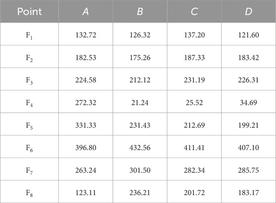
TABLE 3. Flame speeds at different measuring points in pipelines of different structures (A, straight pipeline flame propagation velocity/m∙s-1; B, 45° pipeline flame propagation velocity/m∙s-1; C, 90° pipeline flame propagation velocity/m∙s-1; D, 135° pipeline flame propagation velocity/m∙s-1).
When the shock wave propagates to the corner, it will be disturbed by turbulence, and the flame front will deform, expand and stretch. The surface area of the original spherical flame front increases rapidly, the interface between methane and air is larger, the gas diffusion is more uniform, the combustion is more intense, and the high speed heat release will accelerate the flame propagation. After turning, the flame propagation velocity increases briefly with the increase of propagation distance, and the acceleration of this process is higher than that of the straight tube section under the same conditions, and the trend of flame velocity does not change obviously when the angle of turning is different. Under different turning angles, the increment of flame propagation speed is different, reaching the maximum in the 45° pipeline, followed by the 90° and 135° pipelines. As a result, the existence of the bend accelerates the flame wave obviously, and when the flame wave passes through the bend, the velocity of the flame wave increases significantly.
3.2 Analysis of flame sustainable time in different pipeline structures
The study of flame duration in the process of flame wave propagation plays an important role in ignition of combustible matter in roadway during gas explosion and the time when inhibitor release covers the whole flame zone.
The flame sustaining time at a certain point can be measured by the time differences between vanishing moment and initial rising time of the optical signal at this point (Lv and Wu, 2017). According to this method, the flame sustaining time of different pipe structures are shown in Figure 5. In the straight pipeline, the flame sustaining time decreases continuously with the increase of distance to the ignition source, in 45°, 90°, and 135° pipelines, the variation trend of flame sustaining time is consistent. However, the stay time of the flame leading edge at different measuring points increases gradually, which is attributed to the sudden reduction of flame speed, resulting in a sudden increase in the duration of the flame, the increment of flame sustaining time in the 45° pipeline is significantly higher than those in the 90° and 135° pipelines. Then, the flame sustaining time decreases in all pipeline structures at a slow rate. The reason is that the heat dissipation on the wall surface and the energy consumption may gradually narrow the flame surface. At the same time, combustible gas explosion at the closed end may gradually reduce the pressure intensity in the explosion process. Sparse wave is produced, thereby slowing down the movement speed behind the flame surface and indirectly widening the flame surface. Nevertheless, the widening speed of the flame surface is lower than the narrowing speed. This result reflects that the bend existence will increase the flame surface and cause serious burning damages to the wall surface of pipelines.
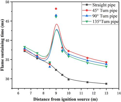
FIGURE 5. Flame sustaining time of different pipeline structures.
3.3 Analysis of overpressure at turn corner in different pipeline structures
Figure 6 presents the peak value of overpressure changes with time before and after the turn of 90 °structural pipeline. The pressure of T3 measurement point before turning first increased and reached the peak rapidly, about 0.48 MPa. During the 22 ms–30 ms period, the pressure of the T3 measurement point increased briefly, which was caused by the shock wave reflected around the corner. The T4 was located on the outside of the corner, and the overpressure peak was the largest, about 0.86 MPa, which was 79.2% higher than that of T3, and the duration was the longest. This is due to the obvious turbulence in the blast flow field, which increases the rate of gas combustion and releases more heat of combustion, resulting in a significant increase in the maximum explosion overpressure. The T5 measurement point is located on the inner side of the corner, and its overpressure peak is 0.43 MPa, which is 10.4% lower than that of T3. After turning, the peak value of overpressure at T6 continues to increase, which is about 16.7%.
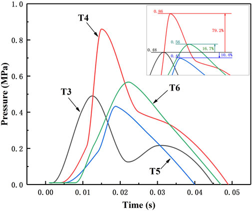
FIGURE 6. Pressure-time curve of 90° structures pipeline.
Figure 7 shows the variation law of the overpressure peaks in different pipeline structures. At the beginning of the explosion (less than 8.55 m distance from ignition source), the development trend of the peak value of explosion overpressure in straight pipelines and turning pipelines is similar, and the peak value of overpressure is gradually increasing. At the corner, the peak value of overpressure at the measuring point outside the corner suddenly increases, while the peak value of overpressure at the inside point decreases. This is due to the occurrence of incident shock waves, reflected shock waves, secondary reflected shock waves, and vortex clusters in the bent pipe, which can easily lead to an increase in shock wave pressure at the turning point, causing particularly severe damage to the wall surface at the turning point. The lateral wall of the corner is more damaged by shock wave than the inner wall. After turning, the peak value of overpressure at different angle measuring points is smaller than that of the same measuring point in the straight pipe, which indicates that the energy of shock wave decreases after turning, and the turning structure plays an inhibiting role on the shock wave propagation. Subsequently, under the influence of opening condition, the explosion overpressure of shock wave decreases gradually.
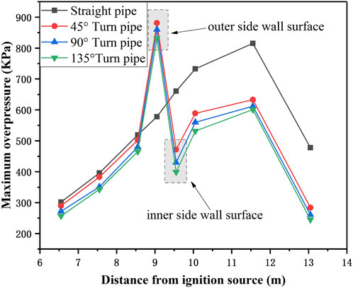
FIGURE 7. Maximum explosion overpressure of different pipeline structures.
4 Conclusion
In this study, the gas explosion test was performed in straight pipelines and pipeline structures with different angles, and the evolution laws of the explosion flame and pressure development during explosion propagation were studied. The research results will provide an important theoretical basis for the development of coal mine explosion suppression technology. The main results are summarized as follows.
1. Different pipeline structures have a greater influence on the law of flame propagation and pressure development. Before turning, with the increase of the distance away from the ignition source, the overpressure peak value and flame velocity gradually increased, and the flame duration gradually decreased. At the corner, the flame propagation speed decreases rapidly, the explosion overpressure and flame duration increase dramatically.
2. The damage caused by the shock wave on the outer wall of the turning corner is the most serious. The bend existence will increase the flame surface and cause serious burning damages to the wall surface of pipelines. The peak overpressure, flame propagation speed, and flame sustaining time in 45° pipelines are higher than in 90° pipelines and 135° pipelines.
3. In order to reduce the intensity of gas explosion and reduce the loss caused by gas explosion, some protective measures should be taken when the tunnel is designed to avoid turning. When it is necessary to set up a turning, corresponding explosion blocking devices should be adopted according to the propagation characteristics of gas explosions inside the turning to reduce the intensity of gas explosions and minimize their losses.
Data availability statement
The original contributions presented in the study are included in the article/Supplementary material, further inquiries can be directed to the corresponding authors.
Author contributions
RS: Writing–original draft. LZ: Writing–review and editing. YN: Writing–original draft. LW: Data curation, Formal Analysis, Writing–original draft. ZH: Data curation, Formal Analysis, Writing–original draft. QJ: Data curation, Formal Analysis, Writing–review and editing. ZL: Data curation, Writing–review and editing.
Funding
The author(s) declare financial support was received for the research, authorship, and/or publication of this article. This research was financially supported by National Natural Science Foundation of China (No’s 52174226 and 52304207), Technology Innovation and Application Development Fund of Chongqing Talent Program (cstc2021ycjh-bgzxm0230), Natural Science Foundation of Chongqing Scientific and Technological (CSTB2022NSCQ-MSX0335), The Science and Technology Research Program of Chongqing Municipal Education Commission (Grant No. KJQN202301525, KJQN202101529). The Project was Supported by Engineering Technology Research Centre for Safe and Efficient Coal Mining (Anhui University of Science and Technology) (NO. SECM2207).
Conflict of interest
Authors RS, LW, ZH, QJ, and ZL were employed by China Coal Technology Engineering Group International Engineering Co., Ltd.
The remaining authors declare that the research was conducted in the absence of any commercial or financial relationships that could be construed as a potential conflict of interest.
Publisher’s note
All claims expressed in this article are solely those of the authors and do not necessarily represent those of their affiliated organizations, or those of the publisher, the editors and the reviewers. Any product that may be evaluated in this article, or claim that may be made by its manufacturer, is not guaranteed or endorsed by the publisher.
References
Ajrash, M. J., Zanganeh, J., and Moghtaderi, B. (2017). Deflagration of premixed methane-air in a large scale detonation tube. Process Saf. Environ. 109, 374–386. doi:10.1016/j.psep.2017.03.035
Cui, G., Wang, S. H., Liu, J. G., Bi, Z., and Li, Z. (2018). Explosion characteristics of a methane/air mixture at low initial temperatures. Fuel 234, 886–893. doi:10.1016/j.fuel.2018.07.139
Frolov, S. M., Aksenov, V. S., and Shamshin, I. O. (2007). Reactive shock and detonation propagation in U-bend tubes. J. Loss Prev. Process Ind. 20 (4-6), 501–508. doi:10.1016/j.jlp.2007.03.010
Huang, F. M., Cao, Z. S., Guo, J. F., and Jiang, S. H. (2020). Comparisons of heuristic, general statistical and machine learning models for landslide susceptibility prediction and mapping. CATENA 191, 104580. doi:10.1016/j.catena.2020.104580
Huang, F. M., Xiong, H. W., Yao, C., Catani, F., Zhou, C., and Huang, J. (2023). Uncertainties of landslide susceptibility prediction considering different landslide types. J. Rock Mech. Geotech. 15 (11), 2954–2972. doi:10.1016/j.jrmge.2023.03.001
Jia, Q. S., Si, R. J., Wang, L., Li, Z., and Xue, S. (2023). Influence of initial gas concentration on methane-air mixtures explosion characteristics and implications for safety management. Sci. Rep. 13, 13519. doi:10.1038/s41598-023-40383-3
Jiang, B. Y., Su, M. Q., Liu, Z., Cai, F., Yuan, S., Shi, S., et al. (2016). Effects of changes in fuel volume on the explosion-proof distance and the multipara meter attenuation characteristics of methane-air explosions in a semi-confined pipe. J. Loss Preven Process Ind. 39, 17–23. doi:10.1016/j.jlp.2015.11.008
Lv, C., and Wu, Z. Z. (2017). Flame thickness and propagation characteristics of premixed methane-air explosion with a small filling ratio in an open-ended steel pipe. Appl. Therm. Eng. 119, 617–621. doi:10.1016/j.applthermaleng.2017.03.104
Mitu, M., Giurcan, V., Razus, D., Prodan, M., and Oancea, D. (2017). Propagation indices of methane-air explosions in closed vessels. J. Loss Prev. Process Ind. 47, 110–119. doi:10.1016/j.jlp.2017.03.001
Niu, Y. H., Zhang, L. L., and Shi, B. M. (2020). Experimental study on the explosion-propagation law of coal dust with different moisture contents induced by methane explosion. Powder Technol. 361, 507–511. doi:10.1016/j.powtec.2019.11.089
Niu, Y. H., Zhang, L. L., Shi, B. M., Yang, Q., and Zhong, Z. (2021). Methane-coal dust mixed explosion in transversal pipe networks. Combust. Sci. Technol. 193, 1734–1746. doi:10.1080/00102202.2019.1711071
Sulaiman, S. Z., Kasmani, R. M., Kiah, M. H. M., Kidam, K., and Ali, R. R. (2014). The infiuence of 90 degree bends in closed pipe system on the explosion properties using hydrogen-enriched methane. Chem. Eng. Trans. 36, 271–276.
Wang, L., Si, R. J., Li, R. Z., and Huo, Y. (2018). Experimental investigation of the propagation of deflagration flames in a horizontal underground channel containing obstacles. Tunn. Undergr. Sp. Tech. 78, 201–214. doi:10.1016/j.tust.2018.04.027
Yan, G. X., Li, Z., Galindo Torres, S. A., Scheuermann, A., and Li, L. (2022). Transient two-phase flow in porous media: a literature review and engineering application in geotechnics. Geotechnics 2, 32–90. doi:10.3390/geotechnics2010003
Zhai, C., Lin, B. Q., and Ye, Q. (2008). The influence of abnormal structure pipeline on the propagation characteristics of gas explosion. J. Xian Univ. Sci. Technol. 28, 274–277.
Zhang, L. L., Yang, Q. Y., Shi, B. M., Niu, Y., and Zhong, Z. (2021). Influences of a pipeline’s bending angle on the propagation law of coal dust explosion induced by gas explosion. Combust. Sci. Technol. 193, 798–811. doi:10.1080/00102202.2019.1673381
Zhu, C. J., Gao, Z. S., Lu, X. M., Lin, B. q., Guo, C., and Sun, Y. m. (2017). Experimental study on the effect of bifurcations on the flame speed of premixed methane/air explosions in ducts. J. Loss Preven Process Ind. 49, 545–550. doi:10.1016/j.jlp.2017.05.016
Keywords: pipeline structure, gas explosion, flame propagation, flame sustaining time, explosion overpressure
Citation: Si R, Zhang L, Niu Y, Wang L, Huang Z, Jia Q and Li Z (2024) Experimental study on characteristics of flame propagation and pressure development evolution during methane-air explosion in different pipeline structures. Front. Earth Sci. 12:1358876. doi: 10.3389/feart.2024.1358876
Received: 20 December 2023; Accepted: 22 January 2024;
Published: 05 February 2024.
Edited by:
Faming Huang, Nanchang University, ChinaReviewed by:
Fanliang Ge, Fuzhou University, ChinaGuobin Cai, Xi’an University of Science and Technology, China
Qianran Hu, Beijing Institute of Technology, China
Haiyan Wang, China University of Mining and Technology, China
Copyright © 2024 Si, Zhang, Niu, Wang, Huang, Jia and Li. This is an open-access article distributed under the terms of the Creative Commons Attribution License (CC BY). The use, distribution or reproduction in other forums is permitted, provided the original author(s) and the copyright owner(s) are credited and that the original publication in this journal is cited, in accordance with accepted academic practice. No use, distribution or reproduction is permitted which does not comply with these terms.
*Correspondence: Leilin Zhang, 82400538@qq.com; Yihui Niu, austyhniu@163.com