Experimental study and mechanism analysis of high-pressure water jet for mud cake cutting during shield tunneling
 Fuquan Ji1
  Pengfei Liu
- 1CCCC Second Harbor Engineering Company Ltd., Wuhan, Hubei, China
- 2Key Laboratory of Safe Construction and Intelligent Maintenance for Urban Shield Tunnels of Zhejiang Province, Hangzhou, Zhejiang, China
- 3Department of Civil and Environmental Engineering, University of Strathclyde, Glasgow, United Kingdom
When the opening rate of the cutter head of tunnel boring machines is insufficient for the removal of excavated soil in a timely manner, the soil tends to accumulate in front of the cutter head and inside the earth or slurry chamber, leading to mud caking. High-pressure water jetting is an effective method for removing mud cakes. This study explored the influence of high-pressure water jet parameters on the efficiency of mud cake cleaning by using highly weathered argillaceous siltstone as experimental materials. Mud cake compaction equipment and high-pressure water jetting devices were developed. In addition, the impact of jetting parameters such as jet pressure and flow rate on the mud cake cutting performance was investigated. The results indicated that with an increase in the erosion distance, the cutting width of the mud cake first increased and then gradually decreased to zero, while the cutting depth progressively diminished. Under the same jet pressure, when the flow rate increased from 49.1 L/min to 110 L/min, the cutting width of the high-pressure water jet increased. With further increase in the flow rate from 110 L/min to 202.8 L/min, the cutting width decreased and the cutting depth increased. Under the same jet flow, the increase in water pressure resulted in greater cutting width and depth.
1 Introduction
Rapid urbanization has led to the construction of a large number of urban tunnels in China (Han et al., 2023; Li et al., 2023). The shield tunneling method has become a preferred approach in urban tunneling projects because of its high efficiency and minimal risk (Liu et al., 2018; Wang er al., 2019; Wang er al., 2022). However, the operation of a shield machine in cohesive geological formations is challenging. When the opening rate of the cutter head fails to meet requirements for the removal of excavated soil in a timely manner, the soil tends to accumulate in front of the cutter head and inside the earth or slurry chamber. This can lead to inefficient mud discharge from the cutter head, increased friction between the cutting tools and soil, and higher temperatures of the excavated materials (Hollmann and Thewes, 2013; Oliveria, 2018; Yang et al., 2023). Under such conditions, the excavated soil often consolidates into a mass, which then adheres to the cutter head as “mud cakes” and significantly hampers the construction efficiency (Langmaack and Lee, 2016; Li et al., 2022; Ding et al., 2023). Shield tunneling for the treatment of mud cakes is often performed using three contemporary methods. In the first method, dispersants are injected into the shield chamber to break down mud cakes (Du et al., 2022; Fang et al., 2022). However, dispersants may also decompose the clay on the tunnel face, potentially causing its collapse. In the second method, mud cakes are manually removed after opening the shield chamber. However, this approach is risky in soft soil strata and exhibits low efficiency in mud cake removal (Min et al., 2015; Wang et al., 2021). The third method involves equipping the shield machine with high-pressure water jetting systems in advance, which are then used to remove mud cakes whenever they are formed. This method is safe and efficient, and it is often used when constructing tunnels with very large diameters (Wang and Feng, 2017; Zhao and Yao, 2017).
Contemporary research on ultra-high-pressure water jets primarily focuses on rock cutting. Hagan (1992) investigated the cutting capabilities on rocks under the combination of rolling cutter tools and high-pressure water jets. The author extended the research to factors such as nozzle diameter, water pressure, jet velocity, and the number of jet cutting passes in the same cut path, among which water pressure was identified as the most significant factor affecting the disruption of rock surface as well as the cutting process. Ciccu and Grosso (2014) discovered that using a 150 MPa water jet on one side of the roller cutter to assist in cutting rock can considerably enhance the efficiency of rock cutting with rolling cutters. Luo et al. (2023) employed numerical simulations and laboratory experiments to examine the effects of cutting depth and spacing between rolling cutters on the capability of high-pressure jets in rock cutting. With the increase in the cutting depth of the high-pressure jet, the vertical force and the rolling force exerted by the rolling cutter decreased considerably. Liu et al. (2023) utilized the Eulerian-Lagrangian Coupling (CEL) method and the finite discrete element method to simulate the rock fracturing process induced by high-pressure water jets. They addressed the challenges of high nonlinearity, fluid solid coupling, and large deformations, and through laboratory experiments, they verified the reliability of the proposed computational approach. Cheng et al. (2022) investigated the impact of high-pressure water jet slotting depth and slotting spacing on the normal indentation force of the rolling cutter, the volume of rock debris, and specific energy. The average peak force noticeably decreased with the increasing slotting depth, and the maximum volume of rock debris and the minimum specific energy were achieved at a slotting depth of 18.14 mm. Zhang et al. (2020) investigated the influence of the depths of slots created by varying high-pressure water jets on the load and efficiency of shield tunneling rolling cutters for rock fragmentation. Regular slots produced by high-pressure water jets enhanced the efficiency of rock breaking by the rolling cutter. This decreased the specific energy required for cutting; the normal force on the cutter head decreased by nearly 40%. Ge et al. (2023) examined the fragmentation characteristics of high-temperature granite and shale under the influence of high-pressure water jets. Their research indicated that rock fragmentation under high-temperature conditions is significantly greater than that under heating-cooling and room temperature conditions. Research on high-pressure water jets has mainly focused on aiding rock breakage, while a few studies have considered their use in removing mud cakes from cutter heads. Xiao et al. (2020) found that when the convergence angle of the nozzle reached 13°, the jet velocity reached the peak at the same pressure. However, the effects of parameters such as nozzle diameter, jet flow rate, and jet pressure on the mud cake cutting efficiency remain unclear. Therefore, it is necessary to conduct in-depth research on the impact of high-pressure water jet parameters on the cutting efficiency of shield tunneling mud cakes.
In this study, initially, an erosion cutting device and a mud cake compaction device were developed. Then, the influence of parameters, such as erosion distance, water jet pressure, and flow rate on the mud cake cutting efficiency was explored. The findings of this study provide a scientific basis for the systematic arrangement of high-pressure water jets in shield tunneling.
2 Experimental introduction
2.1 Experimental materials
The shield tunneling machine encountered a situation where “mud cakes” formed around its cutterhead during its excavation through highly weathered argillaceous siltstone strata in a particular section of the Guangzhou Metro, China. Analysis of the extracted mud cake revealed a water content of 17%–22% and a density of 2.10–2.13 g/cm³. The degree of saturation ranged from 0.824 to 0.992. Under direct fast shearing conditions, the cohesive strength of reshaped soil samples ranged from 44.6 to 47.4 kPa, with an internal friction angle between 23.5° and 25.6°. To explore the effectiveness of high-pressure water jets in eroding these mud cakes, this study used similar highly weathered argillaceous siltstone sourced from the excavation sites in Guangzhou as the test material. As depicted in Figure 1, the largest particle size of the soil sample was 0.13 mm, and >90% of the particles had a size of <0.075 mm. Based on the Chinese Standard Code for the Design of Building Foundation (2019), this soil sample was classified as silty clay. According to the “Geotechnical Testing Standards” (2019), the maximum particle size of soil samples for determining the liquid limit should not exceed 0.5 mm. After removing particles larger than 0.5 mm and highly weathered argillaceous siltstone from the mud cake, the liquid limits were determined as shown in Table 1. The liquid limits of the mud cake were 30.7% and 20.1%, while those of highly weathered argillaceous siltstone were 29.8% and 19.7%, indicating a slight difference. The specific gravities of the two soil samples were 2.85 and 2.83, respectively. Considering the Atterberg limits and particle specific gravity test results, the physical properties of the shield tunnel mud cake and the highly weathered argillaceous siltstone were similar, indicating that the excavated soil within the foundation pit can be used as a substitute for mud cake as a test soil sample. The water content of the mud cake specimens compressed in the laboratory was 20%, with a density of 2.12 g/cm³and a saturation degree of 0.939. Under consolidated fast shearing conditions, the cohesive strength of the soil samples was 44.9 kPa, with an internal friction angle of 24.4°, which was essentially the same as the physical and mechanical parameters of the shield tunnel mud cake.
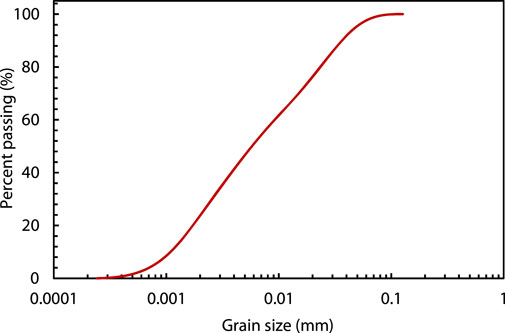
FIGURE 1. Soil gradation curve.
TABLE 1. Physical and mechanical parameters of soil.
2.2 Experimental equipment
2.2.1 Mud cake compaction device
To replicate the state of mud cakes on the cutterhead of a shield tunneling machine, a mud cake compaction device was developed (Figure 2). The device, including its top oil cylinder expansion pipeline, had a height of 2.2 m. The reaction frame had a height and width of 1.7 m and 1.8 m, respectively, and the overall structure resembled a double isosceles trapezoid from front to back. The pressure telescopic rod could be extended up to a maximum length of 1.2 m, and the connected hydro-cylinder could provide a maximum thrust of 2 MPa. The container designed for storing mud cakes was precision-engineered with uniform dimensions to ensure a seamless fit beneath the compaction apparatus. A small hole was strategically located at the bottom center of the mud cake compaction box. This hole assisted in venting during the compaction process to prevent gas pressure from obstructing the normal compaction of mud cakes. The compressed mud cakes produced using this method measured 50 × 50 × 30 cm3.
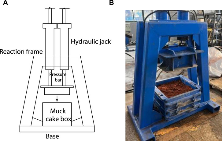
FIGURE 2. Mud cake compaction device. (A) Schematic of the device. (B) Photo of the device.
2.2.2 High-pressure water jet device
The experimental setup of high-pressure water jet is depicted in Figure 3. It comprised a supercharger, hydraulic unit, water supply device, high-pressure pump, accumulator, control valve, and jet nozzle. Water entered through a pipeline to the water supply device, where it was stored, and it was then extracted and pushed out by the high-pressure pump, providing the basic static pressure for its flow. The supercharger, driven by the low pressure of the hydraulic device, moved the piston reciprocally to further increase the pressure, generating the pulse pressure. This pressure was stabilized by the accumulator before it entered the jet control valve, ensuring stable pressure in the jet pipeline. Finally, the high-pressure water jet was controlled and ejected through the control valve.
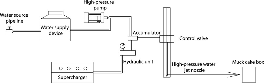
FIGURE 3. Schematic of the working principle of the high-pressure water jet experimental device.
2.2.3 Nozzle structure of the high-pressure water jet device
The cutting capacity of the high-pressure water jet was closely related to its flow rate and water pressure, which were controlled mainly by two factors, nozzle diameter and internal structure. The high-pressure water jet nozzle, as illustrated in Figure 4, employed a flared structure for the internal jet. When the length-to-diameter ratio of the internal transition section was increased, the dynamic pressure and flow velocity at the nozzle outlet also increased, which resulted in an increase in the overall flow rate and pressure of the device.
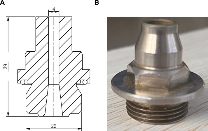
FIGURE 4. High-pressure water jet nozzle. (A) Schematic diagram (mm). (B) Photograph of the device.
3 High-pressure water jet erosion test on mud cakes
Nozzle diameters of 2.0 mm, 3.0 mm, 3.5 mm, and 4.0 mm were selected. Depending on the nozzle size, the pressure capability of the erosion equipment varied, ranging between 37 and 45 MPa. During the experiments, the nozzles of different diameters were switched to adjust the water flow rate while keeping the water pressure constant. Similarly, the nozzles of various diameters were interchanged to alter the water pressure while maintaining a steady flow rate. In the constant pressure tests, water pressure was regulated at 35 MPa, whereas in the constant flow rate tests, the jet flow was set to 110 L/min. Significant erosion effects were evident within 30 s after the water jet impacted the mud cake. If the mud cake was breached within this timeframe, the high-pressure water jet would directly pass through the created hole. Consequently, we set the erosion duration to 30 s. All test conditions are listed in Table 2. The experimental procedure involved the following steps:
(1) The soil sample was dried in an oven and then crumbled. A certain amount of water was added to attain a water content of 20% in the sample. After thorough mixing, the sample was sealed with cling film and left undisturbed for at least 24 h to ensure it was fully moistened.
(2) After the soil sample was uniformly moistened, it was poured into the mud cake box in four installments, each with a mass of 42.75 kg. The soil sample was then subjected to loading (Figure 5A), with each layer of soil compressed to a height of 7.5 cm. After the completion of one layer of compaction (Figure 5B), the surface of the soil sample was roughened to strengthen interlayer connections.
(3) After the final layer of soil sample was completely compacted, soil samples were taken from three positions on the specimen surface by using a cutting ring to determine water content (Figure 5C). If the measured water content differed from the target water content by <1%, the sample had to be prepared again.
(4) The compressed mud cake, along with the box used to secure it, was placed at the target position for high-pressure water jet cutting. To stabilize the mud cake and resist the impact force exerted by the water jet, supplementary weights were strategically placed behind the mud cake box.
(5) The direction of the high-pressure water jet nozzle was adjusted downward to tune the water pressure or flow rate. Once the water pressure or flow rate reached the experimental requirements, the position of the high-pressure water jet nozzle was switched back to the mud cake cutting position for a 30 s wash (Figure 5D).
(6) After the erosion process was completed, the direction of the nozzle’s jet was altered to prevent the erosion of the mud cake, and the high-pressure water jet erosion system was then shut down. Subsequently, the maximum width and depth of the diameter at the eroded location were measured using a caliper.
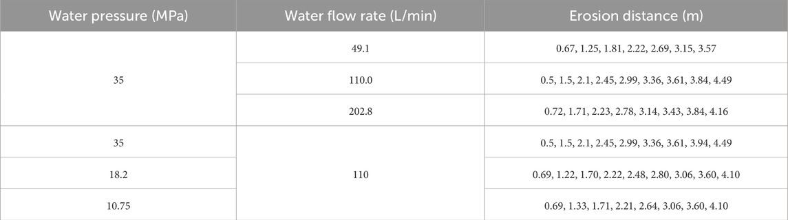
TABLE 2. Overview of the testing conditions.
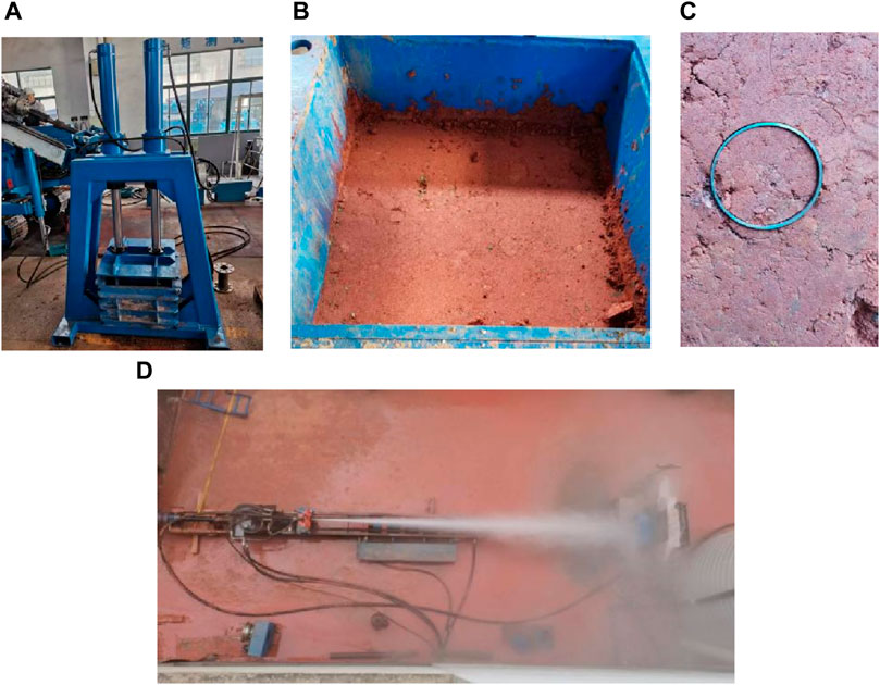
FIGURE 5. Main experimental steps of high-pressure water jetting: (A) compressing soil, (B) completion of one layer of compaction, (C) cutting ring sampling, and (D) cutting mud cake.
4 Experimental results
4.1 Variation in high-pressure water jet cutting capability at different erosion distances
Figure 6 illustrates the variations in both cutting width and cutting depth of mud cake in relation to the erosion distance when a nozzle of 3-mm diameter and 18.2-MPa water pressure was used. At shorter erosion distances, when the distance increased, the cutting width of the mud cake first increased and then gradually decreased to 0, while the cutting depth progressively decreased. At an erosion distance of 2–3 m, the cutting width reached its maximum value of 20 cm. As the cutting width decreased, the depth of cutting also gradually decreased. The reduced cutting effectiveness of the high-pressure water jet made its penetration into the mud cake insufficient.
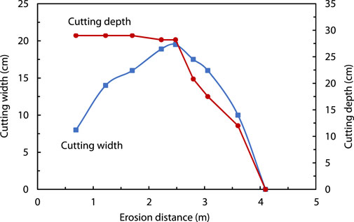
FIGURE 6. Variation in cutting width and depth with distance.
4.2 Variation in high-pressure water jet cutting capability under constant water pressure
When the water pressure was set to 35 MPa, the flow rates for nozzles with the diameters of 2.0 mm, 3.0 mm, and 4.0 mm were 49.1 L/min, 110 .0L/min, and 202.8 L/min, respectively. The variations in cutting width and cutting depth with erosion distance under these working conditions are illustrated in Figure 7. Under constant water pressure and a flow rate of 49.1 L/min, as the erosion distance increased, the cutting width first reached the upper limit and then gradually decreased. At an erosion distance of approximately 3.5 m, the cutting width essentially decreased to zero. At a flow rate of 110 L/min, the maximum cutting width of 23 cm was attained around an erosion distance of approximately 2.5 m, gradually decreasing thereafter. At a flow rate of 202.8 L/min, the maximum cutting width was achieved at an erosion distance of 2.5–3 m. Although the maximum cutting width for this diameter was not the largest among the three nozzles with different sizes, the cutting width for this diameter decreased relatively slowly and was maintained at a certain erosion distance. When the erosion distance d was ≤3 m, at the same erosion distance, the cutting width was the maximum at a flow rate of 110 L/min. When the erosion distance was in the range of 3–4 m, the cutting width achieved with the 4.0-mm nozzle at a flow rate of 202.8 L/min was greater than that achieved with the 3.0-mm nozzle.
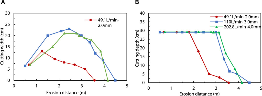
FIGURE 7. Variations in (A) width and (B) depth of high-pressure water jet cutting with erosion distance at constant water pressure.
In terms of cutting depth, as the cutting aperture width gradually decreased, the cutting depth still remained relatively large, almost penetrating through the mud cake, at a flow rate of 49.1 L/min and an erosion distance of 2 m. Moreover, the cutting depth at a flow rate of 202.8 L/min exceeded by those at the flow rates of 49.1 L/min and 110 L/min. Thus, an increase in the flow rate can cause an enhancement in the cutting depth of the mud cake.
4.3 Variation in high-pressure water jet cutting capacity at the same water flow rate
In the constant water flow rate experiments, the jet flow rate was maintained at 110 L/min. However, the 2.0-mm nozzle, even under maximum pressure, could not attain a flow rate of 110 L/min. As a result, nozzles with diameters of 3.0 mm, 3.5 mm, and 4.0 mm were employed, which exhibited the jet pressures of 35 MPa, 18.2 MPa, and 10.75 MPa, respectively, at the flow rate of 110 L/min. Variations in mud cake cutting width and depth with erosion distance under a constant jet flow rate and diverse jet pressures are shown in Figure 8. As shown in the graph depicting changes in cutting width with erosion distance (Figure 7A), nozzles of varying apertures exhibited similar patterns of cutting width variations. Cutting width initially increased to reach the peak and subsequently decreased with increasing distance from the nozzle, which signifies the decrease in the cutting efficiency. At the same flow rate, the smaller the cutting nozzle aperture of the three types of nozzles, the greater was the corresponding pressure, and the higher was their cutting efficiency. Simultaneously, under the same flow rate, jets with higher pressure also achieved a greater maximum cutting distance.
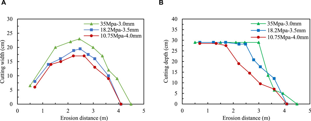
FIGURE 8. Variations in (A) cutting width and (B) cutting depth of high-pressure water jet with erosion distance under the same water flow rate.
Comparison of cutting depths (Figure 7B) showed that the ultimate breakthrough distances for pressures of 10.75 MPa, 18.2 MPa, and 10.75 MPa were 1.7 m, 2.6 m, and 3.2 m, respectively. These results indicated that under the same flow rate conditions, nozzles with higher pressure values attained greater ultimate breakthrough distances when penetrating the mud cake.
5 Discussion on the mechanism of high-pressure water jet cutting of mud cakes
The high-pressure water jet was divided into four segments after it exited the nozzle: the initial segment, transition segment, basic segment, and dissipation segment (Figure 9). In the initial stage, despite intense turbulence and diffusion with the release of water jet into the ambient medium, the velocity of the water jet remained essentially unchanged. The density and dynamic pressure along the axis of the jet also remained constant despite the vigorous energy exchange that occurred because of its interaction with the surrounding environment. After the initial segment, in a brief section, referred to as the transition segment, the outermost water flow expanded outward because of the diffusion of water jet pressure. After the transition segment, there was still a relatively long jet segment in the middle of the water column. Because of natural velocity attenuation and under the influence of friction, both the dynamic pressure and axial velocity of the jet gradually decreased. However, in the cross-section perpendicular to the axis, the dynamic pressure and axial velocity of the jet exhibited a Gaussian distribution. The final section of the high-pressure water jet was the dissipation segment, in which the jet was completely merged with the surrounding environment, and both the jet pressure and axial velocity were very low. The initial, transition, and basic segments exhibit fairly high energy and are commonly used for cutting metals or rock and soil. In contrast, the dissipation segment has relatively low energy and is often used for cleaning purposes.
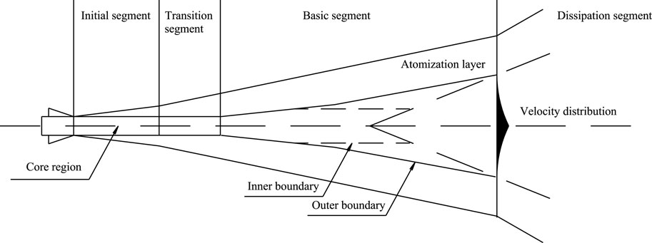
FIGURE 9. Structure schematic diagram of high-pressure water jet.
As depicted in Figure 10, with an increase in the erosion distance, the high-pressure water jet exhibited different forms after cutting through the mud cake. When the cutting distance was small, the jet was in the initial segment, where the velocity and pressure of the inner and outer layers of the jet were nearly equal. Consequently, after the water jet cut through the mud cake, the overall shape of the erosion hole appeared cylindrical. During the up-and-down movement of the water flow, it presented a uniformly wide strip-like cutting pattern (Figure 10A). At this stage, the cutting width was comparatively narrow. As the erosion distance increased, the jet, which was situated at either the transition or the front-end of basic section, exhibited higher water velocity and pressure in its inner layer than those in its outer layer. This differential pattern allowed the inner layer of the jet to effectively penetrate the mud cake, while hindering the penetration of the outer layer. Consequently, the erosion hole, which was aligned with the erosion axis, assumed a truncated-cone form. The width of the hole was larger near the surface of the mud cake and decreased toward its interior (Figure 10B); thus, the cutting width surpassed that of the initial segment. With further increase in the erosion distance, the jet was positioned at the terminal part of the basic segment. The inability of both the inner and outer layers of the water flow to penetrate through the mud cake resulted in the absence of penetrability erosion holes (Figure 10C), which caused a reduction in the cutting width. Additional increment in the erosion distance led to the jet transitioning to the dissipation segment. Consequently, the water flow failed to generate an effective cutting impact, but it manifested an erosion action on the mud cake (Figure 10D), and the cutting width decreased to zero.
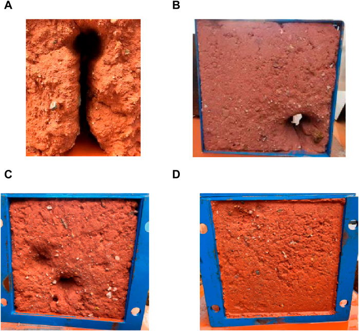
FIGURE 10. Cutting effect at different water jet segments. (A) Uniformly wide strip-like cutting pattern. (B) Truncated-cone form. (C) Absence of penetrability erosion holes. (D) Erosion action on the mud cake.
6 Conclusion
This study developed a self-designed mud cake compaction apparatus and a high-pressure water jet device. The effect of parameters such as jet pressure and flow rate on the cutting width and depth of mud cakes was investigated. The main findings are as follows:
(1) With the increase in erosion distance, the cutting width of the mud cake first increased and then gradually diminished to zero, while the cutting depth decreased from 30 cm to eventually zero.
(2) Under identical jet pressure conditions, an increase in the flow rate from 49.1 L/min to 110 L/min increased the cutting width by the high-pressure water jet. However, as the flow rate continued to increase from 110 L/min to 202.8 L/min, the cutting width decreased. Simultaneously, the cutting depth increased with the increasing flow rate.
(3) At a constant jet flow rate, high water pressure corresponded to the increased cutting width and depth. Essentially, under identical flow rates, a smaller nozzle diameter enhanced the cutting efficiency.
(4) When the mud cake was in the initial segment of the water jet, the erosion hole formed after cutting through the cake assumed a cylindrical shape. Furthermore, when the mud cake was in the transition segment of the jet and the front section of the basic segment, the erosion hole along the erosion axis was in a truncated-cone form. The width of hole was greater near the surface of the mud cake and exhibited a gradual decrease toward the interior. However, when the mud cake was in the latter segment of the basic segment, non-penetrative erosion holes emerged. In the dissipation segment, the water flow primarily manifested erosive effects on the mud cake. These results indicated that the cutting capabilities of the high-pressure water jet were primarily concentrated in the initial and basic segments.
Data availability statement
The original contributions presented in the study are included in the article/Supplementary material, further inquiries can be directed to the corresponding author.
Author contributions
FJ: Investigation, Conceptualization, Writing–review and editing. PL: Supervision, Investigation, Funding acquisition, Data curation, Writing–original draft. ZY: Software, Formal Analysis, Data curation, Writing–review and editing. BW: Validation, Supervision, Software, Resources, Writing–review and editing. QH: Visualization, Validation, Formal Analysis, Writing–review and editing.
Funding
The author(s) declare financial support was received for the research, authorship, and/or publication of this article. The financial supports from the China Postdoctoral Science Foundation (Grant No. 2022M723536) and open fund project of Key Laboratory of Safe Construction and Intelligent Maintenance for Urban Shield Tunnels of Zhejiang Province (Grant No. HZCU-UST-23-03) are acknowledged and appreciated.
Acknowledgments
The authors are also grateful to the help from Shihong Zhai, Xiaofeng Tan, Guanjun You, Haijiang Xu, Gang Li, Qing Yang, Heng Sun, Chao Xu, Zhiyong Yang, and Jun Yu in CCCC Second Harbor Engineering Company Ltd.
Conflict of interest
Authors FJ, PL, ZY, and BW were employed by CCCC Second Harbor Engineering Company Ltd.
The remaining author declares that the research was conducted in the absence of any commercial or financial relationships that could be construed as a potential conflict of interest.
Publisher’s note
All claims expressed in this article are solely those of the authors and do not necessarily represent those of their affiliated organizations, or those of the publisher, the editors and the reviewers. Any product that may be evaluated in this article, or claim that may be made by its manufacturer, is not guaranteed or endorsed by the publisher.
References
Cheng, J., Yang, S., Han, W., Zhang, Z., Jiang, Z., and Lu, J. (2022). Experimental and numerical study on the indentation behavior of tbm disc cutter on hard-rock precutting kerfs by high-pressure abrasive water jet. Arch. Civ. Mech. Eng. 22 (1), 37. doi:10.1007/s43452-021-00360-x
Ciccu, R., and Grosso, B. (2014). Improvement of disc cutter performance by water jet assistance. Rock Mech. rock Eng. 47, 733–744. doi:10.1007/s00603-013-0433-4
Ding, X., Xie, A. Y., Yang, H., and Li, S. (2023). Quantifying multifactor effects on mud cake formation risk for a tunnel boring machine with the analytical hierarchy process. Buildings 13, 355. doi:10.3390/buildings13020355
Du, C., Zhu, H., Wang, S., and Zhang, J. (2022). Test and application study on dispersion and disintegration of mud cake on slurry shield. Tunn. Constr. 42 (5), 847–853. (In Chinese). doi:10.3973/j.issn.2096-4498.2022.05.011
Fang, Y., Yao, Y., Song, T., Wei, L., Liu, P., and Zhuo, B. (2022). Study on disintegrating characteristics and mechanism of cutterhead mud-caking in cohesive strata. Bull. Eng. Geol. Environ. 81, 510. doi:10.1007/s10064-022-03018-x
Ge, Z., Zhang, H., Zhou, Z., Cao, S., Zhang, D., Liu, X., et al. (2023). Experimental study on the characteristics and mechanism of high-pressure water jet fracturing in high-temperature hard rocks. Energy 270, 126848. doi:10.1016/j.energy.2023.126848
Hagan, P. C. (1992). “The cuttability of rock using a high pressure water jet. Western Australia conference on mining geomechanics,” in Proceedings of the Western Australian conference on mining geomechanics, Australia, 8-10 June 1992 (IEEE), 8–10.
Han, J., Wang, J., Yang, W., Wang, X., Ma, R., Wang, W., et al. (2023). Experimental study on the properties of a polymer-modified superfine cementitious composite material for waterproofing and plugging. Case Stud. Constr. Mater. 19, e02552. doi:10.1016/j.cscm.2023.e02552
Hollmann, F. S., and Thewes, M. (2013). Assessment method for clay clogging and disintegration of fines in mechanised tunnelling. Tunelling Undergr. Space Technol. 37, 96–106. doi:10.1016/j.tust.2013.03.010
Langmaack, L., and Lee, K. F. (2016). Difficult ground conditions? Use the right chemicals! Chances–limits–requirements. Tunn. Undergr. Space Technol. 57, 112–121. doi:10.1016/j.tust.2016.01.011
Li, T., Zhao, W., Liu, R., Han, J., Jia, P., and Cheng, C. (2023). Visualized direct shear test of the interface between gravelly sand and concrete pipe. Can. Geotechnical J. 61, 361–374. doi:10.1139/cgj-2022-0007
Li, X., Yang, Y., Li, X., and Liu, H. (2022). Criteria for cutting head clogging occurrence during slurry shield tunneling. Appl. Sci. 12, 1001. doi:10.3390/app12031001
Liu, P., Wang, S., Ge, L., Thewes, M., Yang, J., and Xia, Y. (2018). Changes of Atterberg limits and electrochemical behaviors of clays with dispersants as conditioning agents for EPB shield tunnelling. Tunn. Undergr. Space Technol. 73, 244–251. doi:10.1016/j.tust.2017.12.026
Liu, Z., Ma, Z., Liu, K., Zhao, S., and Wang, Y. (2023). Coupled CEL-FDEM modeling of rock failure induced by high-pressure water jet. Eng. Fract. Mech. 277, 108958. doi:10.1016/j.engfracmech.2022.108958
Luo, X., Zhang, J., Yang, F., He, F., and Xia, Y. (2023). Research on the hard rock cutting characteristics of disc cutter under front-mounted water jet precutting kerf conditions. Eng. Fract. Mech. 287, 109330. doi:10.1016/j.engfracmech.2023.109330
Min, F., Zhu, W., Lin, C., and Guo, X. (2015). Opening the excavation chamber of the large-diameter size slurry shield: a case study in Nanjing Yangtze River Tunnel in China. Tunn. Undergr. Space Technol. 46, 18–27. doi:10.1016/j.tust.2014.10.002
Oliveira, D. (2018). EPB excavation and conditioning of cohesive mixed soils: clogging and flow evaluation. Kingston: Queen's University.
Wang, B., Zhang, H., Li, D., and Li, F. (2021). “Chamber opening under pressure technology of shield,” in Shield tunneling technology in hard-soft uneven stratum and extremely-soft stratum. Key technologies for tunnel construction under complex geological and environmental conditions. Editor K. Hong (Singapore: Springer).
Wang, S., Liu, P., Gong, Z., and Yang, P. (2022). Auxiliary air pressure balance mode for EPB shield tunneling in water-rich gravelly sand strata: feasibility and soil conditioning. Case Stud. Constr. Mater. 6, e00799. doi:10.1016/j.cscm.2021.e00799
Wang, S., Qu, T., Fang, Y., Fu, J., and Yang, J. (2019). Stress responses associated with earth pressure balance shield tunneling in dry granular ground using the discrete-element method. Int. J. Geomechanics 19 (7), 04019060. doi:10.1061/(asce)gm.1943-5622.0001434
Wang, Z., and Feng, H. (2017). Clay cake prevention for a slurry shield cutterhead in argillaceous siltstone stratum. Mod. Tunn. Technol. 54, 217–222. (In Chinese). doi:10.13807/j.cnki.mtt.2017.06.029
Xiao, X., Xia, Y., Mao, X., Wang, Y., Fang, Z., Wang, F., et al. (2020). Effect of the nozzle structure of the large-diameter slurry shield cutterhead on the scouring characteristics. J. Braz. Soc. Mech. Sci. Eng. 42, 157. doi:10.1007/s40430-020-2255-0
Yang, Z., Liu, P., Chen, P., Li, S., and Ji, F. (2023). Clogging prevention of slurry–earth pressure balance dual-mode shield in composed strata with medium–coarse sand and argillaceous siltstone. Appl. Sci. 13, 2023. doi:10.3390/app13032023
Zhang, J., Li, Y., Zhang, Y., Yang, F., Liang, C., and Tan, S. (2020). Using a high-pressure water jet-assisted tunnel boring machine to break rock. Adv. Mech. Engng 12 (10), 168781402096229–16. doi:10.1177/1687814020962290
Keywords: cohesive strata, shield tunneling, mud cake treatment, high-pressure water jet, mud cake cutting
Citation: Ji F, Liu P, Yang Z, Wen B and Hu Q (2024) Experimental study and mechanism analysis of high-pressure water jet for mud cake cutting during shield tunneling. Front. Earth Sci. 12:1371212. doi: 10.3389/feart.2024.1371212
Received: 16 January 2024; Accepted: 05 March 2024;
Published: 19 March 2024.
Edited by:
Jianyong Han, Shandong Jianzhu University, ChinaReviewed by:
Jingqiang Yuan, Chinese Academy of Sciences (CAS), ChinaYongfeng Deng, Southeast University, China
Copyright © 2024 Ji, Liu, Yang, Wen and Hu. This is an open-access article distributed under the terms of the Creative Commons Attribution License (CC BY). The use, distribution or reproduction in other forums is permitted, provided the original author(s) and the copyright owner(s) are credited and that the original publication in this journal is cited, in accordance with accepted academic practice. No use, distribution or reproduction is permitted which does not comply with these terms.
*Correspondence: Pengfei Liu, pfliu0229@foxmail.com