Research on the widths of protective coal pillars in main roadway based on the damaged foundation beam model
 Xinglan Yu
 Tianxin Feng
 Guoqiang Cheng
- College of Energy and Mining Engineering, Shandong University of Science and Technology, Qingdao, China
Long-term stability of the protective coal pillars in coal mines can ensure normal and safe use of roadways; in turn, the integrity of the roadway plays an important role in safe and efficient mining in coal mines. The initial damage and rheological damage caused by coal-seam excavation disturbance have important influences on the selection of reasonable widths of the protective coal pillars. Based on damage mechanics and the theory of elastic foundation beams, a coupled damage constitutive relationship of rock-like materials is proposed in this work by considering the influence of threshold and residual strength to establish the mechanical model of the elastic damage foundation beam. By theoretical analysis and numerical calculation, the differential equation of the deflection curve of the beam is solved, the influence range of the advance abutment pressure under the condition of coupling damage is obtained, and the width of the protective coal pillar is determined. The results show that compared with the elastic foundation beam model, after considering the coupling damage of coal, the influence range of the advance abutment pressure increases with time over a certain duration. At the end of this duration, the influence range of the advance abutment pressure remains almost unchanged. For the case considered in this paper, the long-term stability of the roadway is guaranteed when the width of the coal pillar is 120 m. The potential interference or change related to the specific situation of the site can be studied by changing the relevant parameters in the model to study different working conditions, or the damage of the roof rock beam during the mining process of the working face can be considered, which will be the subject of further research in the future.
1 Introduction
Retaining coal pillars is a common method of roadway protection in coal mines, and a reasonable width of the protective coal pillar in the main roadway is of great significance for improving the resource recovery rate and ensuring safe production (Idris et al., 2015; Rafiei Renani and Martin, 2018; He et al., 2020; Zhang et al., 2021).The main factor determining the width of the protective coal pillar in the main roadway is the influence range of the advance abutment pressure. Many experts have carried out research on the distribution law of the advance abutment pressure of the working face through various practical projects using field measurements, numerical simulations, and similar material model tests (Zhang et al., 2023; Sun et al., 2023). Ren and Ning (2014) carried out numerical simulations, similarity simulations, and field measurements on the distribution law of the advance abutment pressures in shallow buried working faces and found that it was similar to that in the conventional buried coal seam. Using theoretical analyses and numerical simulations, Chang et al. (2017) obtained the relationship between the distribution law of the advance abutment pressure and buried depth of a fully mechanized caving stope in an extra-thick coal seam with a large mining height. Using comprehensive physical similarity simulations, numerical simulations, and theoretical analyses, Huang et al. (2021) and Huang et al. (2023) studied the evolution law of the advance abutment pressure of a large-mining-height working face in a shallow buried coal mine as well as the working face passing through the back channel and two coal pillars. Yu and Wang (2019) used numerical simulations to analyze the distribution law of the advance abutment pressure of a high-cutting fully mechanized working face under the influence of mining. Jiang et al. (2016) conducted a numerical simulation of the working face of a fully mechanized caving stope in an extra-thick coal seam and obtained the influence range of its advance abutment pressure. Li et al. (2023) established a mechanical model of the stress arch under a non-linear load, deduced the morphological equation, and obtained the analytical formula of the influence range of the advance abutment pressure. The relationships between span, buried depth, arch height, concentrated stress coefficient, and influence range of the advance abutment pressure were found via numerical simulations and field measurements. Based on numerical simulations, Zhao et al. (2010) studied the dynamic evolution of the abutment pressure distribution and range of the plastic zone to formulate the relationship between abutment pressure and damage of the front coal-rock.
The above studies mainly focus on the relationships between the distribution law of the advance abutment pressure of the working face and factors influencing the buried depth and mining height mostly through numerical simulations. At present, there is still a lack of a mechanical model and related equations that can be adapted to engineering applications after considering the influences of coal seam damage and rheology. In this paper, the influences of the overlying load and rheology are considered and the elastic coupling damage foundation beam model is used to numerically calculate the deflection differential equation of the beam under the condition of coal-seam damage. The relationship between the influence range of the advance abutment pressure and coal-seam damage is analyzed to provide a theoretical basis for the selection of a reasonable width of the protective coal pillar in the roadway.
2 Establishment of the coupling damage constitutive model
2.1 Coupling damage constitutive model
During the underground engineering excavation, the surrounding rock will inevitably experience an initial damage under the disturbance, resulting in a damaged area with poor mechanical properties (Nick et al., 2023; Wang et al., 2023). At the same time, under the long-term effect of a constant load, the surrounding rock with different kinds of damage in the damaged areas will show more obvious rheological phenomena, which results in the gradual decrease of the elastic modulus and strength of the surrounding rock. In this process, the rheological damage is coupled to the initial damage of the rock, which affects each other.
According to the strain equivalence hypothesis of Lemaitre (1984) and continuous damage mechanics, a damage variable is introduced to describe the damage. The initial damage variable for the excavation disturbance is expressed as D0, rheological damage variable is expressed as D1, and coupling damage variable is expressed as D. The constitutive model of rock coupling damage can thus be obtained as
where σ is the stress of the coupling damage, MPa; E is the elastic modulus of the rock material before damage, MPa; and ε is the strain of the coupling damage.
Then, the coupling damage can be expressed as follows:
2.2 Initial damage constitutive model based on Weibull distribution
The composition of the rock medium is very complex, and it is usually very difficult to describe it mathematically. However, if the rock medium is discretized, it can be approximately described using statistical methods. Tang (1993) divided rock samples into several primitives, and it was assumed that the distribution of mechanical properties of these micro units was statistical, so the Weibull statistical distribution function was used to describe them as follows:
where a is the mechanical property parameter (strength, elastic modulus, etc.) of the rock medium element; a0 is the average value of the mechanical properties of the micro units; m is the shape parameter of the distribution function whose physical meaning reflects the homogeneity of rock medium, which is defined as the uniformity coefficient of the rock medium; and φ(a) is the statistical distribution density of the mechanical property a of the rock primitives, MPa−1.
The damage parameter D0 is a measure of the degree of material damage, and the degree of damage is related to the defects contained in each of the micro units that directly affect their strengths. Therefore, the relationship between the damage parameter D0 and statistical distribution density of the micro unit damage is as follows:
where ε0 is the strain of initial damage.
The damage parameters can be obtained by combining Eqs (3, 4) as
By substituting Eq. (5) into Eq. (1), the initial damage constitutive model of the rock can be obtained as
where σ0 is the stress of initial damage; the material parameters m and a can be obtained from the peak point (εc, σc) in the uniaxial compression stress–strain curve of the rock.When the stress state of the rock specimen is located at the peak stress value, according to the geometric conditions of the curve, the slope of the stress–strain curve at this point is 0. Therefore, the value of the derivative function is 0, and Eq. (6) can be used to derive
At the same time, the point is located on the stress–strain curve, thereby satisfying Eq. (6). Thus, the damage constitutive relationship at the peak point can be obtained by substituting the peak strength point (εc, σc) into Eq. (6) to obtain
According to Eqs (7, 8), the material parameters can be obtained as
Thus, the expression of the foundation damage variable is
2.3 Rheological damage constitutive model
The damage from deterioration of the rock mass parameters over time can be considered by introducing non-constant parameters. From the uniaxial compression creep test of soft rock, Xu, 1997 (Tang, 1993) found that the strength and elastic modulus of the rock decreased with time; the elastic parameter E(t) is gradually attenuated by the elastic modulus E before damage to the long-term elastic modulus E∞, and the damage attenuation curve of E(t) is as shown in Figure 1.
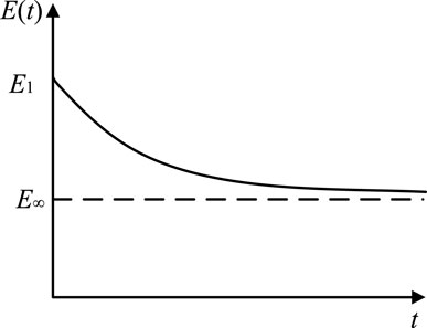
Figure 1. Damage attenuation degradation curve of the rock mass elastic modulus.
The change in the elastic modulus is caused by damage inside the rock, which implies that the rheological damage is also a function of time, and the relationship of the rheological damage variable of the rock over time is obtained as
where E∞ is the final elastic modulus of the rock, MPa; α is the attenuation parameter of the elastic modulus, d−1; and t is the time, d.
When the initial condition t is 0, the damage variable D1 is 0, and there is no damage to the rock; when the time tends toward infinity, the damage variable D1 is 1−E∞/E.
The constitutive model of rock rheological damage is given as follows:
where σ1 is the stress of rheological damage, MPa; ε1 is the strain of rheological damage.
2.4 Damage model considering threshold and residual strength
The above analysis shows that the rock-like material will be damaged as long as it is subjected to a load, and the problem that the damage has a starting point is not considered; that is, the rock-like material has a damage threshold (Zhou et al., 2016). The rock damage threshold refers to the deformation value of the rock subjected to an external load when its internal cracks develop to the stage of instability and expansion. According to rock fracture mechanics, so long as the external load does not exceed a certain critical value, the fracture will not change; however, when this critical value is exceeded, the cracks will expand unstably, at which time the damage continues to accumulate until the rock is destroyed because the rock is still under the action of the external load.
According to rock fracture mechanics, when the rock is damaged and deformed, the internal damage threshold should remain unchanged. Therefore, the damage threshold of the rock is independent of the timeliness, implying that the damage thresholds of the coupling damage variable and initial damage variable are the same. It is assumed that the maximum axial stress σa and maximum axial strain εa corresponding to the non-damage are the starting points of damage; this means that when the stress is σ > σa or the strain is ε > εa, the rock structure starts getting damaged. The strain value in this critical state is defined as the damage strain threshold, and the damage variable is 0.
When the loaded rock starts being damaged, its strength does not immediately become 0, and there is still a residual strength caused by friction. From Eq. (1), it is seen that when the rock is destroyed (when the damage variable is 1), the residual strength is 0. At this time, the rock has no bearing capacity, which is not in line with actual research results, and the residual strength of the rock after destruction cannot be reflected.
Therefore, the Lemaitre strain equivalence hypothesis is modified using the residual strength (Cao et al., 2012), and the revised rock damage constitutive model is as follows:
where σr is the residual strength, MPa.
It can be seen that when the rock is destroyed, it still has a residual strength, which does not change with increase of the rock strain. Obviously, the damage constitutive model at this time not only reflects the deformation process characteristics of the rock residual strength deformation stage but also better reflects engineering practice.
In summary, the damage constitutive model of rock considering the threshold and residual strength is as follows:
When only considering the initial damage, the damage variable is as follows:
When considering coupling damage, the damage variable is as follows:
3 Mechanical model of the elastic damage foundation beam
3.1 Modeling
During advancement of the working face, the immediate roof collapses with mining, so the coal seam will be damaged and surrounding stress is redistributed. To facilitate this study, based on the theory of elastic foundation beam, the main roof is regarded as a rock beam of unit width, and the coal seam and direct roof are regarded as the foundation to establish the semi-infinite model. Considering the pressure of the overlying strata, reaction force of the foundation, and elastic damage of the foundation, the stress analysis of the foundation beam is carried out for the working face side, as shown in Figure 2.
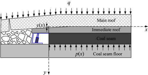
Figure 2. Schematic of the mechanical model of the damaged foundation beam.
According to the theory of beams, the differential equation of the deflection curve of a beam on an arbitrary foundation is as follows:
where Er is the elastic modulus under plane strain condition,
Assuming that the deformation of coal seam in the y direction is uniform,
According to Eqs (15, 18), the differential equation of the deflection curve of the damaged foundation beam considering threshold and residual strength is
where
Only the initial damage is considered here, such that when the model is the initial damage foundation beam model, the damage variable expression is as follows:
Considering the coupling damage, such that when the model is the coupling damage foundation beam model, the expression of the damage variable is as follows:
3.2 Boundary conditions
3.2.1 At the origin
The rock weight of the suspended span of the rock beam is equivalent to the concentrated bending moment M0 and shear force Q0 at the end of the rock beam:
3.2.2 At infinity
According to the boundary conditions of the rock beam, when the rock beam is infinitely far from the recovery working face, its deflection is q/k1, such that
4 Design of the reasonable width of the protective coal pillar
The advance abutment pressure changes during mining of the working face. To ensure long-term stability of the roadway, when designing the reasonable width of the protective coal pillar of the roadway, it is necessary to avoid the influence ranges of the advance abutment pressure after mining of the working face and surrounding rock stress after excavation of the roadway (Li et al., 2022), as shown in Figure 3.
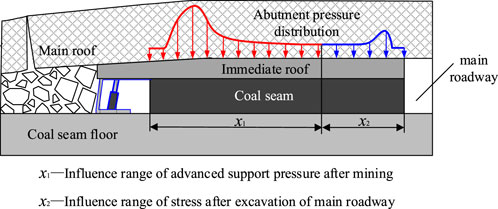
Figure 3. Stress distribution of the reasonable coal pillar width.
If the width of the coal pillar in the roadway is too small, the superposition of the advance abutment pressure and stress influence area after excavation of the roadway may affect the normal use of the roadway. Accordingly, the width range of the coal pillar is as follows:
where x is the width range of the coal pillar, m; x1 is the influence range of the advance abutment pressure, m; and x2 is the influence range of the stress after roadway excavation, m.
The influence range x1 of the advance abutment pressure of the mining face in Eq. (25) is usually calculated as per the empirical formula. The influence range x2 of the surrounding rock stress after excavation of the main roadway is mostly calculated by selecting six times the radius of the outer circle of the roadway (Feng et al., 2019). In this paper, by solving the differential equation of the deflection curve of the mechanical model of the elastic damage foundation beam and based on relevant theoretical knowledge of rock mechanics, more than 5% of the original rock stress is considered the stress disturbance boundary, i.e., the boundary between the elastic zone and original rock stress. The influence range x1 of the advance abutment pressure of the mining face is thus obtained, which provides a new mechanical method for selection of the reasonable width of the protective coal pillar in the roadway.
5 Examples and analysis
In the actual stope of a mine, the structure and properties of the rock are more complex. The rock will inevitably be damaged during mining, and the abutment pressure changes accordingly; however, the ideal model in Figure 2 cannot be completely replaced. Therefore, the application of the foundation beam model is intended to obtain the regularity of the bending moment, deflection, and foundation reaction force of the foundation beam given the coal damage variable from the example to reasonably derive a qualitative judgment on the bending moment and subsidence of the roof as well as the influence range of the advance abutment pressure in the actual stope.
Based on the following data, MATLAB was used for the calculations and plots. According to Eqs (19–24), the bending moment, deflection, and foundation reaction force of the foundation beam in front of the mining face are studied when the coal damage variable changes. The baseline data are as follows (Li et al., 2022): the length of the cantilever beam is 20 m, average volume force of the overlying strata is
5.1 Elastic initial damage foundation beam model
Under the premise of coal elasticity, the deformation characteristics of a foundation beam under elastic and elastic damage conditions are studied. The influences of the initial damage on the deflection, foundation reaction force, and bending moment of the foundation beam are analyzed, and the results are compared with those without damage, as shown in Figure 4.
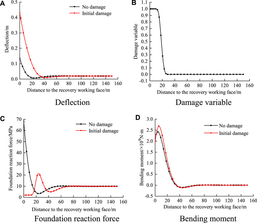
Figure 4. Influences of foundation elasticity and elastic damage on the foundation beam. (A) Defection; (B) damage variable; (C) foundation reaction force/m; and (D) bending moment.
It can be seen from Figure 4 that the effect of coal damage is not considered in the elastic foundation beam model, and the result does not conform to the actual situation where coal in front of the mining face has a certain failure zone range. In contrast, after using the elastic initial damage model, it can be clearly seen from Figure 4B that the damage variable value is 1 in the range of 0–8 m from the mining face and that this area is the complete damage zone. In Figure 4C, the basic reaction force in the complete damage zone reflects the residual strength that does not change with increase in deformation. Stress concentration occurs in the damage zone, and the foundation reaction force reaches its maximum value. In the elastic zone, the beam deflection tends to be stable; that is, the coal deformation tends to be stable with a small value, which does not reach the deformation amount at which damage occurs. The damage value is 0, and the foundation reaction force decreases gradually to finally tend toward the original rock stress value.
Compared with the elastic foundation beam model and considering the coal damage, in Figure 4A and Figure 4D the deflection of the foundation beam on the side near the mining face increases, the peak value of the bending moment increases, the peak value of the foundation reaction force decreases, and the peak positions of the foundation reaction force and bending moment shift toward the deep parts. The influence range of the foundation reaction force increases from 60 m to 75 m in the non-destructive state, and the changes to these variables in the deep part beyond 75 m from the mining face are very small and almost negligible.
5.2 Coupling damage foundation beam model
Considering rheological damage under the premise that the initial damage of the coal has occurred; that is, the force analysis of the foundation beam is carried out under the condition of coupling damage, and the law of deflection, bending moment, and foundation reaction force of the foundation beam over time changes within 1 year are as shown in Figure 5. It can be concluded from Figures 5A, B and Figure 5D that the coupling damage greatly influences the foundation beam. With the increase in rheological time, the deflection of the foundation beam increases gradually, especially in the range close to the mining face, and the changes to the bending moment are relatively small. The variation of the foundation reaction force is large, and the peak value of the foundation reaction force moves toward the depth of the coal seam with increasing time along with increasing influence range.
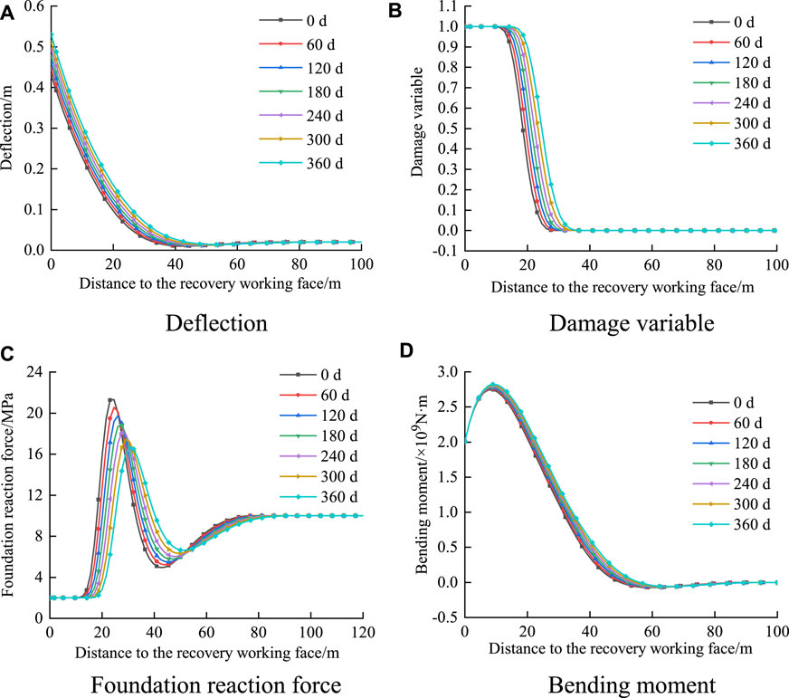
Figure 5. Influence of coupling damage on the foundation beam. (A) Deflection; (B) damage variable; (C) foundation reaction force/m; and (D) bending moment.
It can be seen from Figure 5B that the damage to the coal is unevenly distributed; the damage is more serious within a certain range near the working face, while parts farther away from the working face do not reach the damage threshold, indicating that the damage is more serious with increasing deflection. With increasing creep time, the scope of the failure zone increases, and the scope of the damage zone also increases. In the damage zone, at the same distance from the mining face, the damage to coal is more serious as the creep time increases.
The comprehensive analysis shows that the initial damage and rheological damage of coal will increase the damage range of coal near the mining face, increasing the vertical stress of the coal in the original rock stress part such that the coal may become unstable due to excessive load. Therefore, when selecting the width of the protective coal pillar, the determination of the influence range of the advance abutment pressure should consider not only the initial damage caused by excavation disturbance but also the damage caused by coal rheology so as to ensure long-term stability of the roadway. In this case, the influence range of the advance abutment pressure is approximately 90 m over 1 year.
5.3 Selection of reasonable width of the protective coal pillar
In the above example, the distribution law of the foundation reaction force under varying rheological time is analyzed by considering the coupling damage to determine the reasonable width of the main roadway protection coal pillar. As the rheological time varies, the distribution curve of the foundation reaction force is as shown in Figure 6. From Figure 6, it is seen that before 25 months, the range of the foundation reaction force increases with time; after 25 months, the influence range of the foundation reaction force remains almost unchanged. It can be determined that the influence range of the advance abutment pressure in this case is approximately 100 m.
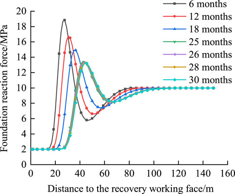
Figure 6. Foundation reaction curves with respect to rheological time.
Based on the parameters selected for the above foundation beam, the size of the roadway is 5.6 m × 3.6 m. Based on the circumcircle of the roadway, the influence range of the surrounding rock stress of the roadway is less than 20 m, so x2 is 20 m. According to Eq. (25), the reasonable width of the protective coal pillar in this case is 120 m, which is consistent with the results obtained through field monitoring and numerical simulation optimization as reported by Li et al. (2022). The practical application shows that the results of the elastic coupling damage foundation beam mechanical model established in this paper are reliable and practical, providing a scientific basis for selecting the width of the main roadway protection coal pillar.
6 Discussion
(1) Zhang established a coupled damage constitutive model of loaded rock under freeze–thaw cycles (Zhang and Yang, 2013), and the infiltration damage variable based on the macro-benchmark variable (stress damage variable) based on creep timeliness and total damage variable under coupling action are defined (Zhang H. et al., 2023). Feng et al. (2018) and Jiang and Wen (2011) established the rock coupling damage expression by considering chemical damage and stress damage. In this paper, the coupled damage equation comprising the initial damage and rheological damage of rock is established, which can be used to study the long-term deformation characteristics of damaged rock after loading. Because the modeling process is not based on any tests, the model applicability is good and reflects the long-term deformation and failure characteristics of different damaged rocks after acceptance. In this model, only the material parameters need to be substituted for the corresponding rock; these parameters are easily obtained from conventional experiments and can provide a theoretical basis for the safety of underground engineering.
(2) In this paper, the elastic damage foundation beam is analyzed through theoretical derivations and numerical calculations. A set of data in the actual working condition was considered for comparison and verification, which proved the correctness of the model while providing a new theoretical basis for the reasonable width selection of the protective coal pillar in the roadway. The potential interference from or changes related to specific situations on-site can be studied by changing the relevant parameters in the model for different working conditions, such as buried depth, elastic modulus of the coal seam, and cantilever beam length, or by considering the damage of the roof rock beam during mining of the working face. These topics will need further research in the future.
7 Conclusion
(1) Based on the theory of damage mechanics and strain equivalence hypothesis, considering the initial damage and rheological damage of the coal seam, the initial damage foundation beam model and coupling damage foundation beam model are established in this study.
(2) Compared with the elastic foundation beam model, once the elastic damage foundation beam model is solved by considering the damage threshold and residual strength, the maximum deflection and bending moment of the foundation beam on the side near the mining face are increased significantly, and the peak positions of the foundation reaction force and bending moment are transferred toward the deep part of the rock. The foundation reaction force reaches its maximum value in the damage zone, and this maximum value decreases thereafter, while the influence range increases under the influence of the initial damage.
(3) According to the analysis of the elastic coupling damage foundation beam model, the deflection of the beam near the mining face increases with time, along with increases to the ranges of the failure and damage zones; furthermore, the peak value of the foundation reaction force decreases, with the peak position shifting toward the deep part, and the bending moment changes minimally.
(4) According to the analysis of the elastic coupling damage foundation beam model, the influence range of the foundation reaction force increases gradually with the rheological time, but the influence range remains almost unchanged after a certain point in time. Therefore, the long-term stability of the roadway can be guaranteed when the width of the protective coal pillar is 120 m as per the engineering application selected in this paper this is consistent with the results obtained from field monitoring and numerical simulations. Therefore, it can be considered that the mechanical model established in this paper is correct and can provide a theoretical basis for the selection of an appropriate coal pillar size.
Data availability statement
The original contributions presented in the study are included in the article/Supplementary Material; further inquiries can be directed to the corresponding author.
Author contributions
XY: data curation, software, and writing–original draft. TF: formal analysis, investigation, validation, and writing–review and editing. GC: writing–review and editing.
Funding
The author(s) declare that financial support was received for the research, authorship, and/or publication of this article. This work was supported by the General Program of the National Natural Science Foundation of China (No. 52074167) and the Shandong Province Graduate Education Quality Curriculum Project Construction Project (No. SDYKC21064).
Conflict of interest
The authors declare that the research was conducted in the absence of any commercial or financial relationships that could be construed as a potential conflict of interest.
Publisher’s note
All claims expressed in this article are solely those of the authors and do not necessarily represent those of their affiliated organizations, or those of the publisher, the editors, and the reviewers. Any product that may be evaluated in this article or claim that may be made by its manufacturer is not guaranteed or endorsed by the publisher.
References
Cao, W., Zhao, H., Li, X., and Zhang, L. (2012). A statistical damage simulation method for rock full deformation process with consideration of the deformation characteristics of residual strength phase. China Civ. Eng. J. 45 (06), 139–145. doi:10.15951/j.tmgcxb.2012.06.001
Chang, W., Ji, C., Yang, Y., Kang, T., and Hou, Y. (2017). Buried depth effect of pressure characteristics of fully-mechanized caving stope in super high seam. Saf. Coal Mines 48 (7), 220–223. doi:10.13347/j.cnki.mkaq.2017.07.059
Feng, G., Wang, G., Wang, P., Guo, J., Yan, Y., and Ren, Y. Study on rational width of the end-mining coal pillar of extra-thickmining panel in permo-carboniferous igneous rock intrusion area[J]. J. Min. Saf. Eng.,2019, 36(1): 87–94. doi:10.13545/j.cnki.jmse.2019.01.013
Feng, X., Wang, W., Wang, R., Yuan, S., and Zhu, Q. (2018). A rheological damage model of sandstone under water-rock chemical interaction. Rock Soil Mech. 39 (09), 3340–3346+3354. doi:10.16285/j.rsm.2017.1819
Geng, Z. (2020). Experimental study on the effect of liquid nitrogen on mechanical properties of coal. Hebei University of Science and Technology.
He, W., He, F., Chen, D., and Chen, Q. (2020). Pillar width and surrounding rock control of gob-side roadway with mechanical caved mining in extra-thick coal seams under hard-thick main roof. J. Mining& Saf. Eng. 37 (02), 349–358+365. doi:10.13545/j.cnki.jmse.2020.02.015
Huang, Q., Gao, X., He, Y., and Wei, B. (2023). Research on strata structure and dynamic load transfer of under coal pillars of last mining section in shallow and close coal seams. J. Min. Saf. Eng. 40 (03), 517–524. doi:10.13545/j.cnki.jmse.2021.0666
Huang, Q., Li, F., He, Y., Gao, B., and Li, J. (2021). Evolution law of the peak of front abutment pressure of large mining height working face in shallow buried. J. Xi'an Univ. Sci. Technol. 41 (01), 1–7. doi:10.13800/j.cnki.xakjdxxb.2021.0101
Idris, M., Saiang, D., and Nordlund, E. (2015). Stochastic assessment of pillar stability at Laisvall mine using artificial neural network. Tunn. Undergr. Space Technol. 49, 307–319. doi:10.1016/j.tust.2015.05.003
Jiang, J., Li, X., Ouyang, Z., Zhao, S., and Feng, Y. (2016). Numerical simulation research on abutment pressure distribution in extra-thick coal seam fully-mechanized caving stope. Saf. Coal Mines 47 (1), 208–211. doi:10.13347/j.cnki.mkaq.2016.01.058
Jiang, L., and Wen, Y. (2011). Damage constitutive model of sandstone during corrosion by AMD. J. Central South Univ. Technol. 42 (11), 3502–3506.
Lemaitre, J. (1984). How to use damage mechanics. Nucl. Eng. Des. 80 (2), 233–245. doi:10.1016/0029-5493(84)90169-9
Li, J., Ma, C., Zhang, C., Ren, Q., Yu, F., Ji, P., et al. (2022). Optimization of protective pillar width of main roadway in weakly cemented soft rock stratum. J. Heilongjiang Univ. Sci. Technol. 32 (05), 582–587.
Li, L., He, F., Xu, X., Qin, B., Lyu, K., Zhai, W., et al. (2023). Study on the evolution of stress arch shape and abutment pressure distribution in close distance coal seams. J. Min. Saf. Eng. 40 (02), 295–303. doi:10.13545/j.cnki.jmse.2022.0146
Nick, B., Wang, C., and Rui, Y. Advances in joint roughness coefficient (JRC) and its engineering applications. J. Rock Mech. Geotechnical Eng., 2023, 15(12): 3352–3379. doi:10.1016/j.jrmge.2023.02.002
Rafiei Renani, H., and Martin, C. (2018). Modeling the progressive failure of hard rock pillars. Tunn. Undergr. Space Technol. 74, 71–81. doi:10.1016/j.tust.2018.01.006
Ren, Y., and Ning, Y. (2014). Changing feature of advancing abutment pressure in shallow long wall working face. J. China Coal Soc. 39 (S1), 38–42. doi:10.13225/j.cnki.jccs.2012.1280
Sun, L., Ding, B., Li, W., Chen, Z., Shang, D., Zhang, Y., et al. (2023). Width optimization and application of narrow coal pillar in gob-side entry driven in thick coal seam in Luzigou Mine. J. Min. Saf. Eng. 40 (06), 1151–1160. doi:10.13545/j.cnki.jmse.2022.0251
Tang, C. (1993). Catastrophes in the process of rock fracture. Beijing: China Coal Industry Publishing House.
Wang, C., Rui, Y., Luo, Z., Du, S., Karakus, M., and Huang, C. (2023). A novel method for determining the three-dimensional roughness of rock joints based on profile slices. Rock Mech. Rock Eng. 56 (6), 4303–4327. doi:10.1007/s00603-023-03274-7
Xu, H. (1997). Study on time effect of soft rock strength and elastic modulus. Chin. J. Rock Mech. Eng. 16 (3), 246.
Yu, X., and Wang, K. (2019). Research on rib spalling prevention technology using deep-hole grouting in advance abutment pressure zone in high cutting working face. Coal Eng. 51 (05), 105–109.
Zhang, B., Wang, P., Cui, S., Fan, M., and Qiu, Y. (2021). Mechanism and surrounding rock control of roadway driving along gob in shallow-buried, large mining height and small coal pillars by roof cutting. J. China Coal Soc. 46 (07), 2254–2267. doi:10.13225/j.cnki.jccs.2021.0234
Zhang, H., Wang, F., Li, H., Yang, G., Shen, Y., Liu, H., et al. Study on creep damage model of coal-rock under different infiltration time and stress level[J]. J. Min. Saf. Eng.,2023b, 40(02): 399–407. doi:10.13545/j.cnki.jmse.2022.0095
Zhang, H., and Yang, G. Damage constitutive model of loaded rock under freeze-thaw condition[J]. J. Wuhan Univ. Technol.,2013,35(07): 79–82.
Zhang, Z., Xu, G., Gao, X., Huang, Z., Liu, Q., and Li, Z. (2023a). Characteristics and mechanism of stope abutment pressure during the whole process. J. Min. Saf. Eng. 40 (06), 1219–1230. doi:10.13545/j.cnki.jmse.2022.0312
Zhao, T., Zhang, H., Chen, Y., and Tan, Y. (2010). Evolution of abutment pressure distribution and impact on coal-rock damage. J. Liaoning Tech. Univ. Sci. 29 (03), 420–423.
Keywords: rheological damage, coupling damage, elastic foundation beam, advance abutment pressure, roadway pillar width
Citation: Yu X, Feng T and Cheng G (2024) Research on the widths of protective coal pillars in main roadway based on the damaged foundation beam model. Front. Earth Sci. 12:1387310. doi: 10.3389/feart.2024.1387310
Received: 17 February 2024; Accepted: 08 April 2024;
Published: 02 May 2024.
Edited by:
Tianshou Ma, Southwest Petroleum University, ChinaReviewed by:
Lei Zhou, Sichuan University, ChinaChangshuo Wang, Ningbo University, China
Jianguo Wang, China University of Mining and Technology, China
Copyright © 2024 Yu, Feng and Cheng. This is an open-access article distributed under the terms of the Creative Commons Attribution License (CC BY). The use, distribution or reproduction in other forums is permitted, provided the original author(s) and the copyright owner(s) are credited and that the original publication in this journal is cited, in accordance with accepted academic practice. No use, distribution or reproduction is permitted which does not comply with these terms.
*Correspondence: Guoqiang Cheng, 1336720578@qq.com