Stable operating limits and improvement methods for hydropower and photovoltaic integration through MMC-HVDC systems
 Maolan Peng1*
  Wei Zhao
- 1Electric Power Research Institute, China Southern Power Grid Joint Laboratory of DC Transmission Equipment and Submarine Cable Safety Operation, Guangzhou, China
- 2State Key Laboratory of Alternate Electrical Power System with Renewable Energy Sources, Beijing, China
This paper addresses the critical need to determine the stable operating limit of modular multilevel converter-based high voltage direct current (MMC-HVDC) systems, particularly concerning the integration of extensive renewable energy sources. To achieve this, the steady-state mathematical model and state-space model of bundled hydropower and photovoltaic integration through MMC-HVDC systems are established. A novel methodology considering steady-state and small-signal stability constraints is proposed to compute the stable operating region of the system. The quantitative assessment reveals that diminishing AC system short-circuit capacities amplify restrictions from small-signal stability constraints, thereby reducing the system's stable operating region. Eigenvalue and participation factor analyses shed light on the pivotal factors affecting small-signal stability in weak AC systems. To expand the system's stable operating region, a supplementary frequency damping control strategy is proposed. The theoretical analysis and calculation results are validated by building a simulation model for the bundled hydropower and photovoltaic integration through MMC-HVDC systems in PSCAD/EMTDC.
1 Introduction
With the green and low-carbon transformation of the power industry, clean energy sources like hydroelectric, wind, and photovoltaic (PV) have witnessed significant development (Sun et al., 2017). While new energy sources like photovoltaics offer advantages in terms of being clean and cost-effective, they come with drawbacks such as being stochastic and intermittent, and showing high variability of power generation (Shafiullah et al., 2022). These characteristics pose challenges to the safe and stable operation of the power grid. Hydroelectric power, as a high-quality and controllable clean energy source, can help mitigate the fluctuations in photovoltaic power output. The complementary operation of hydroelectric and photovoltaic power is a crucial approach to enhancing photovoltaic integration and improving the overall stability of the power grid (Yan et al., 2022).
The flexible control methods offered by the modular multilevel converter-based high-voltage direct current (MMC-HVDC) allow for independent control of active and reactive power. This technology can provide AC voltage support to new energy stations and dynamically compensate for reactive power, making it a viable option for large-scale exports of renewable energy (Yang et al., 2023).
However, the stable operating range of bundled hydro and photovoltaic integration through MMC-HVDC systems remains unclear, especially when various combinations of hydro and photovoltaic capacities are considered. When traditional power sources like hydropower are available to support the system, the grid-following control strategy is available for MMC-HVDC systems. It should be noted that the proportion of hydropower capacity in relation to the total capacity influences the short-circuit capacity that the sending-end system can provide. When the sending-end AC system strength reduces, the power transmission capability of the system becomes limited, and it might even experience operational instability. Such limitations could significantly impact the integration capacity of renewable energy sources. Hence, it is imperative to investigate the stable operating limits and influencing factors of bundled hydropower and photovoltaic integration through MMC-HVDC systems.
For the study of the stable operation region of MMC-HVDC, Zhang et al. (2016) used the point-seeking calibration method to analyze the steady-state operation area under different short-circuit ratios, considering the stability constraints of capacity, voltage, and modulation ratio. Zhou et al. (2014) and Huang and Wang (2018) used the maximum transfer power to illustrate the effect of phase-locked loops (PLLs) and short-circuit ratios on the stable operating region of the system. Zhang et al. (2021) used a graphical approach to analyze the steady-state operating area, considering the voltage stability constraints, which illustrates the influence of short-circuit ratios on the steady-state operational region. Zhang et al. (2011) synthesized voltage and current constraints and used space-vector theories to obtain the power operation point with the minimum voltage offset or the maximum output power. Li et al. (2023) investigated the influence of LCC-HVDC on the steady-state operation area of VSC-HVDC under different control modes and AC system intensities. Zhao et al. (2023) analyzed the key factors affecting the power quality and safety of the system and proposed a calculation method for the steady-state operation area of the system. The above literature reports have analyzed the stable operation region of MMCs connected to Thevenin-equivalent AC systems under active or passive operating conditions but have not considered the system characteristics and constraints associated with integrated renewable energy.
In terms of enhancing the small-signal stability of VSC-HVDC when connecting to weak AC systems, the existing literature reports have proposed some control methods. In Arani and Mohamed (2017) the concept of virtual impedance is introduced to improve the small-signal stability of VSC systems connected to weak AC grids. Suul et al. (2016) expanded the stable operating range of phase-locked loops by introducing impedance compensation terms. Guo et al. (2017) presented a frequency-based synchronization control (FSC) method that combines the characteristics of Vector Current Control (VCC) and phase-locked synchronization control (PSC) with favorable steady-state and transient control effects. To explore the factors influencing the stability limits of the bundled hydro and photovoltaic integration through MMC-HVDC and to propose the method for improving its stable operation capability, the paper developed the mathematical model of the system and conducted research.
The remainder of the paper is organized as follows: In Section 2, the steady-state mathematical model and state-space model of the bundled hydro and photovoltaic integration through MMC-HVDC systems are established. In Section 3, the steady-state operation constraints and small-signal stability constraints of the system are illustrated. Based on these two types of constraints, a method for calculating the stable operating region of MMC-HVDC systems is proposed. In Section 4, the variation characteristics of the steady-state operation constraints and the small-signal stability constraint boundaries under different AC system short-circuit capacities are quantitatively evaluated. In addition, the key influencing factors that limit the stable operating region of the system in weak AC systems are revealed. Furthermore, a supplementary frequency damping control (SFDC) strategy based on the phase-locked loop output frequency of MMCs is introduced to enhance the small-signal stability of the system in weak AC systems. In Section 5, a simulation model for bundled hydro and photovoltaic integration through MMC-HVDC systems is developed in PSCAD/EMTDC to validate the correctness of the theoretical analysis and computational results. Section 6 presents the conclusion of the paper.
2 Bundled hydropower and photovoltaic integration through MMC-HVDC system modeling
2.1 System structure
The unipolar structure of the bundled hydropower and photovoltaic integration through MMC-HVDC systems studied in this paper is shown in Figure 1, where the hydropower at the sending end can provide the AC voltage and frequency support to the system. The PV plants and hydropower are connected to the point of common coupling (PCC) of MMC-HVDC.
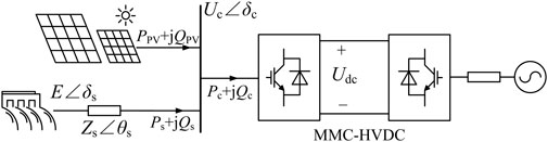
FIGURE 1. Schematic diagram of bundled hydropower and photovoltaic integration through the MMC-HVDC system.
2.2 Steady-state mathematical model
The steady-state equivalent circuit of the bundled hydropower and photovoltaic integration through MMC-HVDC systems studied in this paper is shown in Figure 2. Here Rline, Xline, and Cline are the transmission line parameters of the PV plant; Xt_PV is the equivalent reactance of the step-up transformer of the PV plant; UPV∠δPV and Pt_PV+jQt_PV are the voltage and power of point of connection (POC) of the PV plant, respectively; Rs and Xs are the resistance and reactance of the hydropower system, respectively; Uline∠δline and Uc∠δc are the voltage of the line capacitance and PCC, respectively; E∠δs is the hydroelectric unit terminal voltage; PPV+jQPV and Ps+jQs are the power flowing into PCC from PV and hydropower, respectively; Pc+jQc is the power flowing into MMC, and Udc is the DC voltage of the MMC converter station.
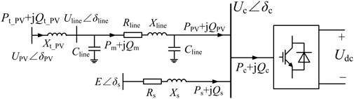
FIGURE 2. Steady-state equivalent circuit of the rectifier of bundled hydropower and photovoltaic integration through the MMC-HVDC system.
Based on the voltage drop in the outgoing line of the hydropower, the power flowing from the hydropower into PCC can be expressed as follows:
Similarly, the power flowing relationship between the converging bus of the PV plant and PCC can be expressed as
In (2), YC denotes the capacitive admittance of the line capacitor Cline.
According to the power balance relationship, the following relationship Eq. 3 exists between the power flowing into the MMC converter station and the power flowing into PCC from the PV plant and the hydropower:
2.3 State-space model
2.3.1 State-space modeling of PV, hydropower, and MMC subsystems
The PV plant studied in this paper adopts the controlled source aggregation equivalent model, and the control method adopts the fixed unit power factor control, with the topology shown in Figure 3. nPV is the aggregation number of photovoltaic generating units. Zline_PV = Rline+jXline is the line impedance between POC and PCC. kt1_PV and kt2_PV are the turns ratios of the two-stage boost transformer. ugabc_PV is the three-phase AC voltage of the point of connection, and igabc_PV is the three-phase AC current flowing out from the point of connection. Udc_PV is the voltage across the DC capacitor. The modeling method for extracting power from the PV array and controlling the PV inverter is based on the work of Liu et al. (2016), which provided a 28-order state-space model of the PV plant as follows:
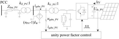
FIGURE 3. Structural diagram of the equivalent PV station.
In Eq. 4, the input variable UPV = [Udcref_PV, igqref_PV]T. Here, Udcref_PV and igqref_PV are the DC voltage outer loop and q-axis current inner loop reference values of the PV inverter.
The hydropower system is divided into the electrical part of the generator and the control part of the hydropower unit. Based on the convex pole effect of the hydraulic turbine, the generator body adopts the classical rotor three-winding model, which takes into account the role of the excitation winding and the cross and straight axis damping windings. According to the voltage equation and magnetic chain equation, the seven-order state space model of the generator is established.
In the control part of the hydroelectric unit, the exciter is considered a first-order inertial system, and the regulator-type governor consists of three parts: the regulator, the electro-hydraulic servo system, and the prime mover. Among them, the regulator adopts a parallel PID controller, and the prime mover adopts a rigid water strike model and a classical linear hydraulic turbine model, as shown in Figure 4.
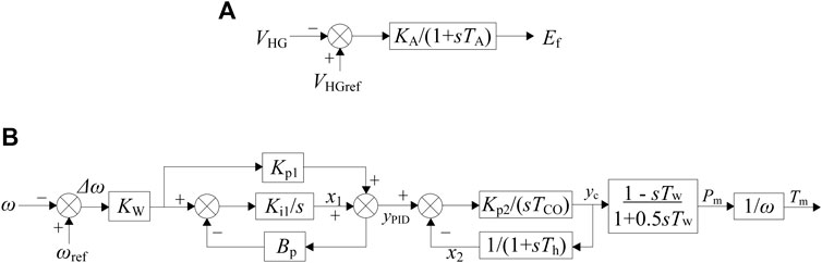
FIGURE 4. Hydropower generator controllers. (A) Hydroelectric generator exciter. (B) Hydroelectric generator governor.
The state-space model is as follows:
In Eq. 5, the exciter gain and amplification time constant are denoted as KA and TA, respectively. Kw represents the amplification coefficient of frequency deviation. Bp is the permanent speed droop. Kp1 and Ki1 are the gain values of the proportional and integral components of the regulator, respectively. Kp2 is the gain of the proportional component of the electro-hydraulic servo system. Tco and Th are the switching time constants of the hydraulic servo motor and the travel feedback time constant, respectively, and Tw is the time constant of the water hammer effect. The deviation of the hydraulic turbine output AC voltage VHG from its reference value VHGref goes through the exciter to generate the excitation no-load electromotive force Ef. The deviation of the frequency Δω goes through the parallel PID control regulator to obtain the command value of the guide vane opening signal yPID, and the electro-hydraulic servo system keeps the guide vane opening yc the same as the command value yPID. The linear model of the prime mover obtains the hydroelectric output active power PHG and mechanical torque Tm.
The MMC converter station adopts a small-signal model that considers the internal dynamic characteristics, and MMC adopts a classical current vector controller with constant active and reactive power control. The converter station can be modeled by referring to Guo et al. (2023), and the state-space model is as follows:
In Eq. 6, the input variable UMMC = [Pref, Qref]T, where Pref and Qref are the active and reactive outer loop reference values of MMC.
2.3.2 Modeling of the interface between PV, hydropower, and MMC systems
The control systems of the PV field station, hydropower generator, and MMC converter station are based on different dq rotational coordinate systems, so when establishing the mathematical model of the system, it is necessary to establish the interface between the three state-space models. The relative positions of the dq rotational coordinate systems of the PV plant, hydropower generator, and MMC converter station are shown in Figure 5.
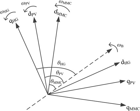
FIGURE 5. Relative position of the coordinate system of each system.
The dashed line in Figure 5 represents the synchronous rotation coordinate axis, and the rotation frequency is the rated angular frequency ωB. The frequency and phase of the phase-locked loops of the PV field station and the MMC converter station are represented by ωPV, θPV, ωMMC, and θMMC, respectively, and the conversion expressions between the two state variables are shown in (7).
The output frequency and phase of the hydropower generator are ωHG and θHG, respectively, and the conversion expressions between the two state variables are shown in (8).
3 Stable operation constraints
3.1 Steady-state operation constraints
The system current constraints are composed of (1)–(3), and the operating points that satisfy the system current constraints can be obtained by association. In addition to the current constraints of the system, other steady-state operation constraints of the converter need to be considered as follows.
3.1.1 Voltage modulation constraint
MMC uses the nearest level modulation (NLM) method. In order to prevent the system from being in an over-modulated state during operation, it is necessary to constrain the valve-side voltage Uc of MMC within a certain range so that it complies with the modulation ratio constraints:
where Uc is the effective value of the base wave line voltage on the valve side, Udc is the DC voltage, and m is the modulation ratio.
3.1.2 Overcurrent constraint
During the operation of the MMC-HVDC system, the current input to the converter should be kept within the allowable tolerance of the device; otherwise, it may lead to damage in the IGBT components and other devices. Therefore, the MMC-HVDC system should fulfill the following current overload constraints:
where Immc represents the current flowing into MMC, Imax stands for the maximum value of the fundamental current on the AC side of MMC, Smax is the maximum value of the capacity of the MMC converter station, and Ubase is the AC voltage reference value.
3.1.3 Submodule capacitor voltage ripple constraint
The submodule capacitor voltage ripples need to be controlled within the engineering allowable range, like 5%–10%. According to Qin et al. (2021), the specific expression for the submodule capacitance voltage constraint is
3.1.4 Voltage of the PCC constraint
Considering the actual operation of the project, the voltage of PCC is limited to ±5%, i.e.,
3.1.5 Voltage of the POC constraint
The voltage deviation of POC in the PV plant is limited to −3% to +7%, i.e.,
3.2 Small-signal stability constraint
In order to ensure the small-signal stability of the bundled hydropower and photovoltaic integration through MMC-HVDC systems, it is necessary to satisfy the small-signal constraints, which require linearizing the state-space model of the system to obtain the 55th-order small-signal model, whose expression is shown in (14).
where X is a state vector of order 66 × 1, A is the state matrix of order 66 × 66, B is the input matrix of order 66 × 4, and U is the input vector, U = [Udcref_PV, igqref_PV, Pref, Qref]T.
The unipolar simulation model of bundled hydropower and photovoltaic integration through MMC-HVDC systems shown in Figure 1 is built in PSCAD/EMTDC, and the main parameters are shown in Table 1.
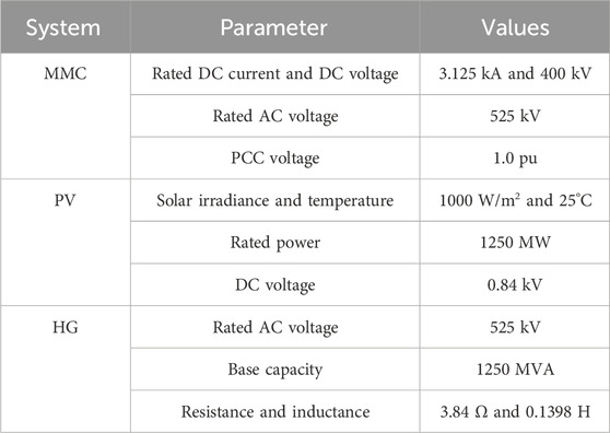
TABLE 1. Main parameters of the system.
The eigenvalues of the system state matrix A are solved based on the given system operating point; if the real part of all the eigenvalues is negative, the small-signal stability constraint is satisfied, implying
3.3 Stable operating region calculation method
Procedures to determine the stable operating region of the system are described as follows, and the flowchart of these procedures is shown in Figure 6:
(i) Step 1: consider a set of operating points and calculate (PPV, QPV), (Ps, Qs), and (Pc, Qc) using (1)–(3).
(ii) Step 2: if the operating point satisfies the stability constraints of (9)–(13), then calculate the eigenvalues of the system at the operating point using (14). If the operating point satisfies the small-signal stability constraint of (15), the system can operate stably at this operating point.
(iii) Step 3: check whether all operating points are judged. If not, repeat steps 1 and 2.

FIGURE 6. Flowchart for the steady-state operation area.
4 Influential factors and enhancement methods for the stable operating limit of MMC-HVDC
4.1 Impact of short-circuit capacity on the stable operating region
To investigate the changing characteristics of the stable operating region under different short-circuit capacities (Sd) of sending-end AC systems, the stable operating regions of the system were computed. Maintaining a constant photovoltaic output ensures that only the strength of the sending-end AC system affects the stable operating region of the system during operation. Here, taking a photovoltaic output of 0.7 pu as an example, the stable operating regions of the system are illustrated in Figures 7A, B, C for sending-end AC system short-circuit capacities of 4500, 3500, and 2500 MVA, respectively. The short-circuit capacity Sd can be calculated using (16):
where Zs is the impedance of the hydroelectric system and UN is the rated voltage.
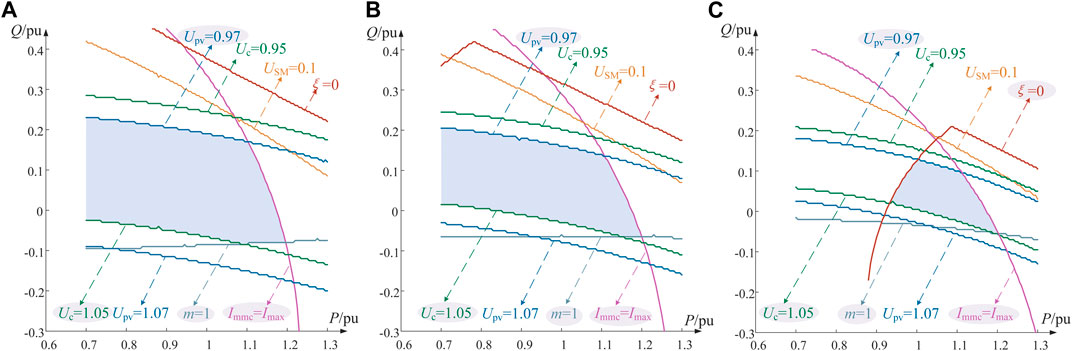
FIGURE 7. Stable operation area under different short-circuit capacities. (A) Sd=4500MVA, (B) Sd=3500MVA, (C) Sd=2500MVA.
In Figure 7, P and Q represent the active and reactive power flow into the MMC converter, respectively, the solid lines of different colors depict the boundaries of various constraint conditions, and the blue region represents the stable operating region that satisfies all constraint conditions. From Figure 7, it is evident that the system’s stable operating region is primarily constrained by the voltage constraint of POC, voltage constraint of PCC, overcurrent constraint, modulation ratio constraint, and small-signal stability constraint. As the AC system’s short-circuit capacity decreases, the voltage of PCC and POC constraints progressively limits the reactive power stability operating range of the system. Under the condition of a short-circuit capacity of 2500 MVA, as shown in Figure 7C, it is evident that the small-signal stability constraint notably restricts the system’s stable operating region.
4.2 Key factors influencing the stable operating region in weak AC systems
With the decrease in the short-circuit capacity of the sending-end AC system, small-signal stability constraints notably restrict the system’s stable operating region. In the context of weak AC systems, small-signal stability constraints become one of the key limiting conditions governing the stable operating limits of MMC-HVDC systems.
To further analyze the factors influencing the system's small-signal stability, characteristic value analysis and sensitivity analysis methods can be employed to investigate the effects of short-circuit capacity on the system’s small-signal stability. Based on the established small-signal model of photovoltaics through MMC-HVDC systems, at a photovoltaic output of 0.7 pu, the AC system’s short-circuit capacity was reduced from 7500 MVA to 2000 MVA, resulting in the system’s root locus depicted in Figure 8.
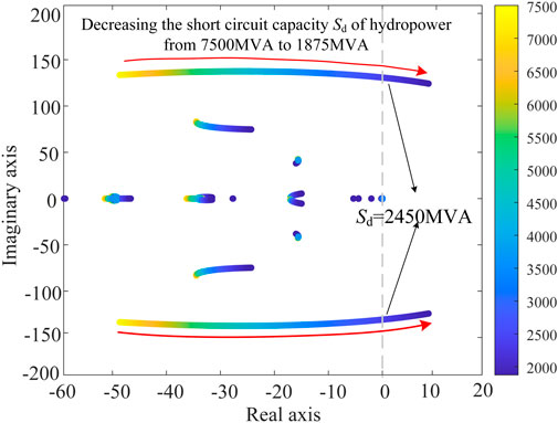
FIGURE 8. Loci of the eigenvalues when the short-circuit capacity of hydropower changes.
From Figure 8, it is evident that as the short-circuit capacity provided by hydroelectric decreases, the system’s dominant modes gradually approach the imaginary axis, resulting in a reduction in small-signal stability. When the short-circuit capacity decreases to 2450 MVA, the dominant mode crosses the imaginary axis, leading to a small-signal instability within the system.
In order to investigate the critical control factors affecting the dominant mode, an analysis of the system’s dominant mode was conducted using the participation factor analysis approach. The participation factors of various state variables within the system are illustrated in Figure 9, where the horizontal axis represents the state variables and the vertical axis represents the degree of participation of each variable.
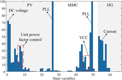
FIGURE 9. Participation factor analysis of the dominant mode.
From Figure 9, it is evident that the dominant mode of the system is associated with control elements related to the phase-locked loop control and inner/outer loop control of MMC and a photovoltaic grid-connected inverter. Notably, the participation factor of the phase-locked loop control significantly exceeds that of other control elements.
4.3 Methods to enhance system stability limits in weak AC systems
In weak AC systems, the small-signal instability of MMC-HVDC systems is significantly influenced by the PLL control of MMC. This highlights the importance of the observability and controllability of state variables related to MMC’s PLL in governing the dominant mode. To enhance system stability, this section proposes a supplementary frequency damping control based on the output frequency of MMC’s PLL. The aim is to mitigate system instability caused by PLL control, thus improving the stable operating limit of MMC-HVDC systems under weak AC system conditions.
As depicted in Figure 10, the deviation Δω in the angular frequency of PLL from the rated angular frequency in MMC, after passing through the rate feedback loop, is compensated for the outer loop of active power control in the form of a supplementary damping component. This compensation aims to suppress small-signal instability caused by PLL of MMC. Kf represents the differential gain, with a value of 0.003, and Tf represents the filtering time constant, with a value of 1s. When the supplementary damping control is activated within the grid-connected inverter, S1 is set to 1. Under the operating conditions with a short-circuit capacity of 2000 MVA, the parameter feasible region for Kf and Tf is illustrated in Figure 11. A comparison of the damping ratio of the dominant mode with and without supplementary damping control under various short-circuit capacities is shown in Figure 12.
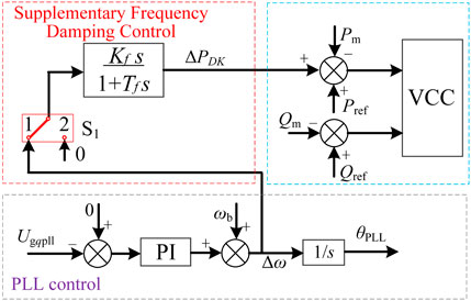
FIGURE 10. Supplementary frequency damping controller.
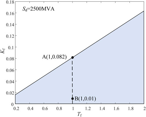
FIGURE 11. Feasible region of KDF and TF.
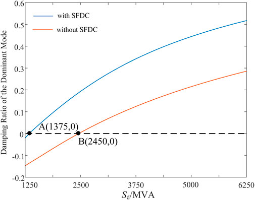
FIGURE 12. Damping ratio of the dominant mode under different short circuit capacities.
At a short-circuit capacity of 2500 MVA and under the condition of photovoltaic-rated active power output, the calculated stable operating region of the system with supplementary damping control is depicted in Figure 13A, while the comparison of stable operating regions before and after the introduction of damping control is illustrated in Figure 13B.
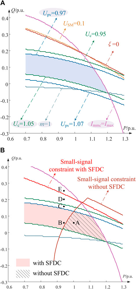
FIGURE 13. Steady-state operation area with a supplementary frequency–voltage damping controller. (A) Stable operating region of the system with SFDC. (B) Comparison of stable operating regions with and without SFDC.
Figure 13 shows that compared to the scenario without damping control, the introduction of damping control increases the stable operating limit for active power transmission in MMC-HVDC systems from 0.7 pu to 1.2 pu The supplementary frequency damping control enhances the stable operating limit of MMC-HVDC systems under weak AC conditions, consequently improving the system’s capacity to integrate renewable energy sources.
5 Simulation validation
To validate the accuracy of the aforementioned calculations and theoretical analysis, a simulation model of a bundled hydroelectric and photovoltaic integration through MMC-HVDC systems was developed in PSCAD/EMTDC. The AC system had a short-circuit capacity of 2500 MVA with a photovoltaic output of 875 MW, and the system parameters are listed in Table 1. The following scenarios were set: at the initial state, the system operated at point A, as shown in Figure 14B (Pref = 1.0 pu; Qref = 0.06 pu). At t = 2 s, the system transitioned from point A to point B (Pref = 0.94 pu; Qref = 0.06 pu). At t = 4 s, supplementary damping control was activated. At t = 6 s, the system transitioned from point B to point C (Pref = 0.94 pu; Qref = 0.16 pu). At t = 8 s, the system transitioned from point C to point D (Pref = 0.94 pu, Qref = 0.20 pu). At t = 10 s, the system transitioned from point D to point E (Pref = 0.94 pu; Qref = 0.26 pu). The system’s dynamic response characteristics are depicted in Figure 14.
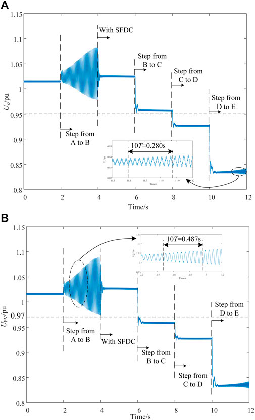
FIGURE 14. Simulation verification of stability constraints under different operating points. (A) Voltage of POC. (B) Voltage of PCC.
Figure 14 shows that the system transitioned from point A to B at 2 s. Without the introduction of supplementary damping control, the power operating point jumped from inside the small-signal stability constraint boundary to outside, leading to a small-signal instability in the system. The proposed supplementary damping control was activated at 4 s, effectively suppressing system oscillations. At this point B, the system operated within the small-signal stability constraint boundary after the control was implemented.
The system transitioned from point B to C at 6 s, and the power operating point jumped from within the voltage of the POC constraint boundary to outside. The voltage of PCC changed from 1.03 pu to 0.96 pu, exceeding the constraint range of 0.97 pu to 1.07 pu. The system transitioned from point C to D at 8 s, and the power operating point jumped from within the voltage of the PCC constraint boundary to outside. The PCC voltage changed from 0.96 pu to 0.93 pu, with a voltage deviation exceeding ±5%. The system transitioned from point D to E at 10 s, and the power operating point jumped from within the small-signal constraint boundary to outside, resulting in a small-signal instability.
These results demonstrate that the proposed supplementary frequency damping control effectively enhances the system’s small-signal stability margin. The PSCAD/EMTDC simulation results at different operating points align with the theoretical analysis’s constraint boundaries, providing strong validation of the accuracy of the proposed method for calculating the stable operating region of the MMC-HVDC system and the accompanying theoretical analysis.
6 Conclusion
In this paper, steady-state mathematical models and state-space models for the bundled hydroelectric and photovoltaic integration through MMC-HVDC systems are established. In addition, the variations in the stable operating region of MMC-HVDC systems under different short-circuit capacities are quantitatively evaluated. The following conclusions were drawn:
1) A method that comprehensively takes into account both the steady-state constraints and small-signal stability constraints for bundled hydroelectric and photovoltaic integration through MMC-HVDC systems is introduced. This method allows for the calculation of stable operating regions under varying short-circuit capacities of the sending-end AC system.
2) A supplementary frequency damping control method is proposed in this paper, which compensates the phase-locked loop output frequency for the active power outer loop of MMC through the rate feedback loop. This control method enhances the small-signal stability of the bundled hydroelectric and photovoltaic integration through MMC-HVDC systems in cases of low short-circuit capacities. Consequently, it improves the stable operating limit of the system.
Data availability statement
The original contributions presented in the study are included in the article/Supplementary Material; further inquiries can be directed to the corresponding author.
Author contributions
MP: formal analysis, project administration, writing–original draft, and writing–review and editing. LF: data curation, methodology, and writing–review and editing. SZ: writing–original draft. WZ: writing–review and editing.
Funding
The author(s) declare that financial support was received for the research, authorship, and/or publication of this article. This work is supported by the Science and Technology Project of China Southern Power Grid EHV Power Transmission Company, China Southern Power Grid Joint Laboratory of DC transmission Equipment and Submarine Cable Safety Operation (Research on Key Technologies to improve Enhance the New Energy Integration Capability of Flexible HVDC Transmission System, No. 0120002022030301SJ00046).
Conflict of interest
The authors declare that the research was conducted in the absence of any commercial or financial relationships that could be construed as a potential conflict of interest.
Publisher’s note
All claims expressed in this article are solely those of the authors and do not necessarily represent those of their affiliated organizations, or those of the publisher, the editors, and the reviewers. Any product that may be evaluated in this article, or claim that may be made by its manufacturer, is not guaranteed or endorsed by the publisher.
References
Arani, M., and Mohamed, Y. (2017). Analysis and performance enhancement of vector-controlled VSC in HVDC links connected to very weak grids. IEEE Trans. Power Syst. 32 (1), 684–693. doi:10.1109/TPWRS.2016.2540959
Guo, C., Liu, W., Zhao, C., and Iravani, R. (2017). A frequency-based synchronization approach for the VSC-HVDC station connected to a weak AC grid. IEEE Trans. Power Deliv. 32 (3), 1460–1470. doi:10.1109/TPWRD.2016.2606495
Guo, C., Xu, L., Yang, S., and Jiang, W. (2023). A supplementary damping control for MMC-HVDC system to mitigate the low-frequency oscillation under low inertia condition. IEEE Trans. Power Deliv. 38 (1), 287–298. doi:10.1109/TPWRD.2022.3186940
Huang, Y., and Wang, D. (2018). Effect of control-loops interactions on power stability limits of VSC integrated to AC system. IEEE Trans. Power Deliv. 33 (1), 301–310. doi:10.1109/TPWRD.2017.2740440
Li, T., Li, Y., and Zhu, Y. (2023). Research on the voltage supporting capability of multi-VSC-HVDC subsystems operation strategy to receiving-end LCC-HVDC network in weak AC grid. CES Trans. Electr. Mach. Syst. 7 (1), 11–20. doi:10.30941/CESTEMS.2023.00007
Liu, S., Liu, P., and Wang, X. (2016). Stochastic small-signal stability analysis of grid-connected photovoltaic systems. IEEE Trans. Industrial Electron. 63 (2), 1027–1038. doi:10.1109/TIE.2015.2481359
Qin, S., et al. (2021). Study on the safe and stable operation area for the converter station under the scenarios of renewable energy generation sending through islanded MMC-HVDC. Power Syst. Technol. 45 (02), 785–793. doi:10.13335/j.1000-3673.pst.2020.0290a
Shafiullah, M., Ahmed, S., and Al-Sulaiman, F. (2022). Grid integration challenges and solution strategies for solar PV systems: a review. IEEE Access 10, 52233–52257. doi:10.1109/ACCESS.2022.3174555
Sun, J., Li, M., Zhang, Z., Xu, T., He, J., Wang, H., et al. (2017). Renewable energy transmission by HVDC across the continent: system challenges and opportunities. CSEE J. Power Energy Syst. 3, 353–364. doi:10.17775/CSEEJPES.2017.01200
Suul, J., Arco, S., Rodríguez, P., and Molinas, M. (2016). Impedance-compensated grid synchronisation for extending the stability range of weak grids with voltage source converters. IET Generation, Transm. Distribution 10 (6), 1315–1326. doi:10.1049/iet-gtd.2015.0879
Yan, R., Yao, X., Liu, D., Qiao, R., Zhang, L., Zhang, K., et al. (2022). Optimal design of hydro-wind-PV multi-energy complementary systems considering smooth power output. Sustain. Energy Technol. Assessments 50, 101832. doi:10.1016/j.seta.2021.101832
Yang, R., Shi, G., Zhang, C., Li, G., and Cai, X. (2023). Internal energy based grid-forming control for MMC-HVDC systems with wind farm integration. IEEE Trans. Industry Appl. 59 (1), 503–512. doi:10.1109/TIA.2022.3205569
Zhang, L., Nee, H., and Harnefors, L. (2011). Analysis of stability limitations of a VSC-HVDC link using power-synchronization control. IEEE Trans. Power Syst. 26 (3), 1326–1337. doi:10.1109/TPWRS.2010.2085052
Zhang, Z., Chen, D., Givaki, K., and Xu, L. (2021). A less-intrusive approach to stabilize VSC transmission against highly variable grid strength. IEEE J. Emerg. Sel. Top. Power Electron. 9 (6), 7199–7211. doi:10.1109/JESTPE.2020.3030362
Zhang, Z., Xu, Z., Jiang, W., and Bie, X. (2016). Operating area for modular multilevel converter based high-voltage direct current systems. IET Renew. Power Gener. 10 (6), 776–787. doi:10.1049/iet-rpg.2015.0342
Zhao, H., Chen, W., He, G., and Wang, J. (2023). A new shared module soft open point for power distribution network. IEEE Trans. Power Electron. 38 (3), 3363–3374. doi:10.1109/TPEL.2022.3224972
Keywords: hydropower, photovoltaic, MMC-HVDC, stable operating limit, supplementary frequency damping control
Citation: Peng M, Feng L, Zhang S and Zhao W (2024) Stable operating limits and improvement methods for hydropower and photovoltaic integration through MMC-HVDC systems. Front. Electron. 4:1342795. doi: 10.3389/felec.2023.1342795
Received: 22 November 2023; Accepted: 26 December 2023;
Published: 16 January 2024.
Edited by:
Wenjie Liu, Northwestern Polytechnical University, ChinaReviewed by:
Fei Li, Hefei University of Technology, ChinaLujie Yu, Tianjin University, China
Moke Feng, Chongqing University, China
Copyright © 2024 Peng, Feng, Zhang and Zhao. This is an open-access article distributed under the terms of the Creative Commons Attribution License (CC BY). The use, distribution or reproduction in other forums is permitted, provided the original author(s) and the copyright owner(s) are credited and that the original publication in this journal is cited, in accordance with accepted academic practice. No use, distribution or reproduction is permitted which does not comply with these terms.
*Correspondence: Maolan Peng, pml1081170912@163.com