Fabrication methods and performance in fuel cell and steam electrolysis operation modes of small tubular solid oxide fuel cells: a review
 Victor M. Orera
 Miguel A. Laguna-Bercero
 Angel Larrea
- Instituto de Ciencia de Materiales de Aragón, CSIC-Universidad de Zaragoza, Zaragoza, Spain
Higher energetic density, better resistance to thermal stresses, and smaller starting times as compared with conventional planar stacks, make the so-called microtubular SOFC (mT-SOFCs with diameters in the millimeter size region) devices suitable for portable applications in the sub kilowatt energy range. However, fabrication of mT-SOFCs is a challenging process, where a number of ceramic layers with different compositions and characteristics have to be placed together in the cylindrical device. Several co-sintering processes have to be performed at different temperatures and using distinct atmospheres to complete cell fabrication. In this review, we summarize recent activity in the field of fabrication and characterization of mT-SOFCs, including the use of mT-SOFCs for steam electrolysis.
Introduction
High temperature ceramic solid oxide fuel cells (SOFCs) are well-known electrochemical devices that directly convert, in a very efficient way, the chemical energy of hydrogen-enriched fuels, including hydrocarbons, into electricity and heat power (Singhal and Kendall, 2003; Cooley, 2009). They are promising energy conversion devices due to their fuel flexibility, good electricity generation efficiency, and high efficiency for total power generation.
These devices have been proposed for different stationary, mobile, and military applications (Singhal, 2002). In SOFCs, heat losses can be used to heat the system, thus increasing total energy efficiency. Moreover, SOFC devices are silent, clean, and efficient. They can also be a part of a distributed generation network, significantly reducing electricity transmission losses.
Solid oxide fuel cells are also foreseen for high temperature steam electrolysis (HTSE) devices or solid oxide electrolysis cells (SOECs) (Laguna-Bercero, 2012). SOEC operation was first reported in the 1980s by Doenitz and Erdle (1985) and by Isenberg (1981). In the meantime, a rapidly increasing interest in these systems has developed. The reason is that HTSEs need less electric energy demand than low temperature electrolysis devices because a part of the total energy can be supplied by the heat resulting from system losses or by waste heat from other power sources. In addition to steam electrolysis, SOEC devices have also been proposed for different applications (Graves et al., 2011). In particular, Martínez-Frias et al. (2003) described a natural gas-steam assisted electrolyzer (NGASE). As in the case of SOFCs, the chemical flexibility of SOEC is a pluspoint for applications. Steam and CO2 co-electrolysis to produce syngas using nuclear or renewable electricity and waste heat is a promising way of reusing CO2 in the energy cycle (Fu et al., 2010; Jensen et al., 2010).
Solid oxide fuel cell technology is based on ceramic electrolytes made of oxygen ion conductors or proton conductors. Conventional SOFCs consist of an anode made of a Ni–YSZ (Yttria Stabilized Zirconia) porous cermet, an YSZ electrolyte and a lanthanum strontium manganite, La1−xSrxMnO3 (LSM) cathode. They are manufactured in planar or tubular geometries, and the structural cell component can be any of the electrodes or the YSZ electrolyte itself. In general, these SOFCs are large devices used for stationary applications that present long start-up and shutdown times, as well as extremely low thermal shock resistance. The relatively thick electrolyte, especially when the electrolyte acts as the support (>100 μm), leads to operation temperatures above 900°C.
Nowadays, research in SOFCs seeks to reduce the SOFC operating temperature down to 500–750°C (intermediate temperature solid oxide fuel cells, ITSOFC) to avoid many of the inconveniences related to a high operation temperature. The relevant parameter here is the electrolyte electrical resistance Relect or, more specifically, the area specific resistance (ASR) that should be as small as possible, ≈0.1 Ω cm2. Relect depends on the material ionic conductivity σi (Ω−1 cm−1) and on the electrolyte thickness. Thin film SOFCs with 100 nm thick YSZ electrolyte have been reported to be operative at temperatures as low as 350°C with an output power density of 400 mW cm−2 at 400°C (Huang et al., 2007). Another innovative design is to use self-supporting electrolyte membranes prepared by laser machining. In this approach, a laser beam is used to machine the surface of a sintered electrolyte membrane to produce thin areas (<10 μm), but maintaining a thicker support surrounding area to ensure the structural strength of the membrane. Thus, intermediate temperature electrolyte-supported cells can be prepared (Larrea et al., 2011).
Another strategy is to look for better ionic conductors than YSZ, for example, scandia and ceria stabilized zirconia (10Sc1CeSZ), doped gallates (La0.9Sr0.1Ga0.8Mg0.2O3−δ, LSGM), and doped ceria Gd0.2Ce0.8O2−δ (GDC) electrolytes have been used for ITSOFC manufacturing. New chemical systems, some of them presenting much higher ionic conductivity than YSZ, have been explored for SOFC electrolytes, as described in a recent review by Orera and Slater (2010). However, manufacture of gas-tight electrolyte layers with good mechanical and chemical stability is still the unsolved problem for the applicability of these new electrolyte materials.
In the case of the electrodes, the aim is to reduce the overpotential associated to the chemical reactions taking place at the electrode–electrolyte interfaces. The relevant parameters describing electrode performance are oxygen diffusivity and the surface exchange coefficient, together with the electrical conductivity. Doped manganites, LSM, are thermo-chemically stable materials at the sintering temperatures, but present low diffusivity and surface exchange values. As a consequence, conventional SOFC cathodes are made of LSM/YSZ mixed porous composites. The oxygen reduction reactions take place at the so-called triple-phase boundaries (TPB), where the ionic conductor, electronic conductor, and pores meet. In addition, the activity of conventional cathodes decreases when the operation temperature is lowered; thus, the overpotential at the oxygen electrode is high at low temperatures, and different cathode materials have to be used for low temperature operation (Shao and Haile, 2004). The most frequently used cathodes for low temperature SOFC are mixed ionic electronic conductors (MIEC) with perovskite crystal structure such as the La0.6Sr0.4Co0.2Fe0.8O3−δ (LSCF) cobalt-ferrite (Tai et al., 1995; Wang and Mogensen, 2005; Tiez et al., 2006). However, LSCF cannot be heated at T > 800°C in contact with YSZ because it reacts producing zirconate insulating phases. Protective thin layers, generally GDC layers, have to be inserted between the YSZ electrolyte and the cathode to prevent such reactions. In addition to the favorable situation derived from low temperature operation, it is worth noting that reducing the operation temperature is detrimental to the direct use of hydrocarbon fuels. The internal fuel reforming is not active below 700°C and external heated reformers will be necessary in this case.
The most frequently used anode material is the porous Ni/YSZ cermet (Zhu and Deevi, 2003). Conventional anode compositions are 50/50 Ni/YSZ with >40 vol% open porosity. This material shows a good performance in the whole temperature range, but when used with hydrocarbon fuels, carbon deposition in the Ni catalyzer is detrimental for cell operation. Steam has to be added to the fuel to induce a water–gas reaction to avoid the problem. Copper and ceria catalyzers also seem to improve the anode performance when carbon fuels are used (Atkinson et al., 2004). Another matter of concern with Ni anodes is their relatively high intolerance to sulfur impurities (Singhal and Kendall, 2003; Yang et al., 2009) and their poor resistance to re-oxidation events when fuel flow is accidentally interrupted (Pihlatie et al., 2009). Moreover, the elevated cost of current SOFC devices and poor cell durability (Yokokawa et al., 2008) are the fundamental issues limiting the general application of this technology.
As for cell geometries, the tendency in SOFC design is to facilitate weight reduction and to increase resistance to thermal cycles. As a result, new lightweight SOFC configurations are emerging for applications in mobile systems (Lang et al., 2008), for example, the application of SOFCs as auxiliary power units (APU) up to powers of 5 kW is foreseen (Lamp et al., 2003). Among the different SOFC geometries proposed for portable applications, the microtubular SOFC (mT-SOFC), first developed by Kendall (1993) is probably the preferred configuration. mT-SOFCs are defined as tubular cells with diameters in the millimeter range. The first generation of mT-SOFCs was electrolyte-supported on thin YSZ tubes (100–200 μm) produced by extrusion (Kendall, 1992). Details of this initial development of mT-SOFCs were recently collected by Kendall (2010).
Development of electrode-supported mT-SOFCs allows fabrication of a thin electrolyte layer, thus lowering the cell operation temperature (Sammes et al., 2005). As volumetric power density (VPD) scales with the inverse of the tube radius, small tubular SOFCs reaches VPD values around 2.5 W cm−3, higher than those of large diameter tubular SOFC and planar SOFCs (Kendall et al., 2003). Another advantage of mT configuration derives from the low mechanical constraints of the tubular geometry, when compared with planar cells. As a result, an exclusive characteristic of mT-SOFCs is the rapid start-up time (Kendall and Sales, 1994). In fact, Bujalski et al. (2007) demonstrated that individual YSZ-supported mT-SOFCs could be switched on in <1 min, stacks will need much longer start-up times. In a recent paper, Kendall and Meadowcroft (2013) discussed the benefits of reducing tube diameter, both in fast cell thermal response and in the increase of cell mechanical strength. They conclude that even though reducing cell diameter dramatically increases cell strength and makes cell start-up times much smaller, thermal inertia and other balance of plant (BoP) problems related with stack management are now the limiting aspects which remain unsolved for mobile applications.
Efforts are being made to overcome the difficulties found for mT-SOFC use (Mori et al., 2009; Kanawka et al., 2011; Wang et al., 2011; de la Torre et al., 2013) and interest in mT-SOFCs has risen over recent years, as indicated by the increase of scientific contributions in this area. However, there are only a few review papers devoted to mT-SOFCs. Here, we would like to point out those of Lawlor et al. (2009), Howe et al. (2011) and the very recent and comprehensive paper by Lawlor (2013). Recently, mT-SOFCs have also been proposed for high temperature solid oxide electrolyzers (Hashimoto et al., 2009) and a reversible FC-HTSE behavior has been reported (Laguna-Bercero et al., 2010, 2011b).
Some basic studies of mT-SOFCs related, for example, to the influence of microstructure on fuel cell performance (Suzuki et al., 2009), mechanical strength (Sammes and Du, 2003), operation under hydrocarbon fuels (Buchinger et al., 2006; Dhir and Kendall, 2008; Calise et al., 2011), resistance to anode redox-cycling (Kendall et al., 2007; Monzón and Laguna-Bercero, 2012), and thermal cycling (Sarkar et al., 2007; Du et al., 2008), have also been reported. Recent advances in mT-SOFC technology include development of hollow fibers (HF) (Othman et al., 2011a), metal-supported cells (Suzuki et al., 2011a), infiltrated cells (Torabi et al., 2012), and stack modeling and design (García-Camprubí and Fueyo, 2010; Watanabe et al., 2012b).
Nevertheless, there are a few companies, summarized in Table 1, offering devices based on small or mT-SOFCs. Other companies and research centers developing mT-SOFC stacks are Adelan and University of Birmingham, National Institute of Advanced Industrial Science and Technology in Japan (AIST), Alberta Research Council and Korea Institute of Technology.
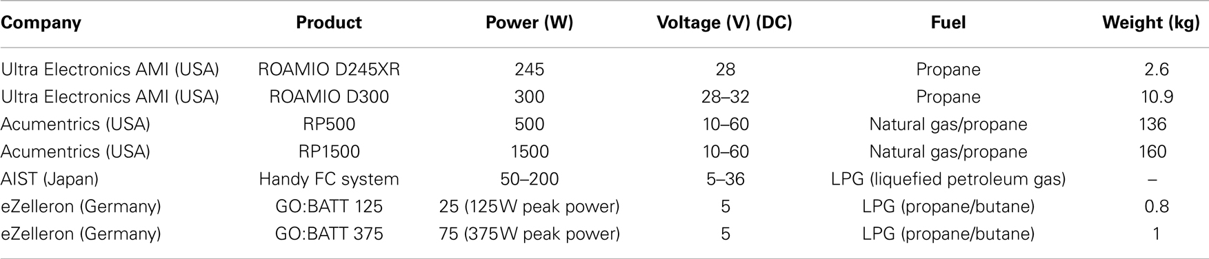
Table 1. Summary of mT-SOFC based products fabricated by different companies.
In the present review, we will focus on mT-SOFCs cell manufacturing methods and recent advances in cell performance, both in SOFC and SOEC operation modes.
Basics of Cell Operation
As an illustrative example, we are going to describe the behavior of a Ni–YSZ/YSZ/LSM–YSZ mT-cell operated at 950°C in the reversible FC and SOEC mode (Laguna-Bercero et al., 2011b). In Figure 1 we represent the current density–voltage (j–V) measured at 950°C fueled with 120 ml min−1 humidified pure hydrogen (3% H2O). The polarization curve was carried out down to 0.6 V, 600 mW cm−2, which correspond to a small 7% fuel utilization value (Uf). Uf is defined as the ratio between the spent fuel flow versus the inlet fuel flow. In SOEC mode, the curve has been recorded up to −0.4 mA cm−2 (1.55 V). Analysis of the polarization contributions to the j–V curve in FC mode operation can be made using the model given by Kim et al. (1999) for anode-supported YSZ-based cells. The current dependent voltage is given by:
E0 is the Nernst potential, which depends on temperature and gas partial pressures, F = 96485.3 C mol−1 is the Faraday constant, and R = 8.3145 J mol−1 K−1 is the gas constant. a and b parameters describe the activation polarization in the high current limit (Tafel limit). Electrode activity depends on material properties, microstructure, gas partial pressure, current density, and electrode microstructure. For anode-supported cells, the anode-limiting current, jas, is the limiting parameter defining concentration polarization. jas is defined as the current density at which all the fuel has been starved and its partial pressure is zero. jas, which should be as high as possible, is directly proportional to the effective anode diffusivity (Da) and inversely proportional to the anode thickness. Anode gas permeability increases with pore volume fraction, Vap, and decreases with the tortuosity factor, τa, and anode thickness. Both volume fraction and tortuosity factor are parameters that depend on anode microstructure.
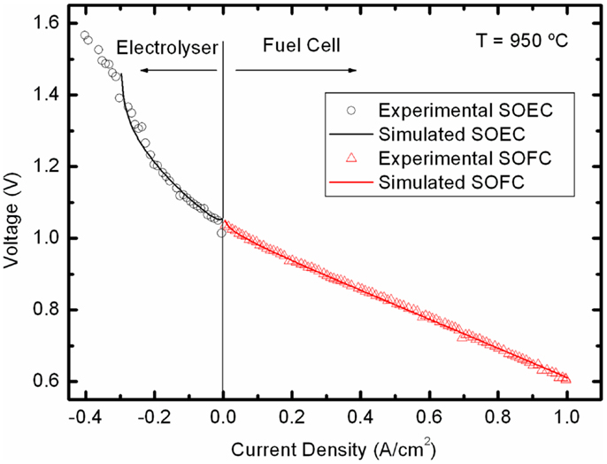
Figure 1. Experimental j-V curves in both SOFC and SOEC modes of a Ni-YSZ/YSZ/LSM-YSZ mT-SOFC and their corresponding fitting using Eqs 1 and 2. Operation conditions: 950°C using humidified pure hydrogen as fuel Laguna-Bercero et al. (2011b).
Comparison of the measured voltage in open circuit, OCV, and the Nernst potential is an excellent test of the electrolyte gas-tightness and electronic leaks. In fact, when there is no electronic current leak through electrolyte, the measured OCV should be equal to E0:
where U0(T) is the standard voltage and the logarithmic term stands for the equilibrium constant of the oxidation reaction. If there is an electronic current leak I = jL, OCV = V0 − jLRT, OCV drops, and there is water production at the anode side, jL(A)/2F mol H2O/s.
It is interesting to note that in a tubular cell there is a variation in gas concentration along the tube axis associated to the parallel flow of fuel and air. In anode-supported tubes, variable concentrations of fuel and water are found, with the former being higher at the inlet and the latter being higher at the outlet. For high values of fuel utilization, the cell potential may change significantly along the tube axis.
For SOEC mode operation, the following equation derived from Eq. 1 is proposed:
Fitting the experimental j–V data of Figure 1 to Eq. 3, the four parameters Ri, a, b, and jas can be obtained (see Table 2) for both FC and SOEC modes. The ohmic resistance Ri includes ionic electrolyte resistance as well as other ohmic contributions from electrodes, current collectors, and interfaces. In FC mode, the total resistance values are slightly higher than those around 0.1 Ω cm2 obtained in the best planar SOFCs at this temperature, but also similar to those of other microtubular and SOEC cells (Serincan et al., 2009). The fitting value of jas = 2 A cm−2 for the saturation current is about two times smaller than typical SOFCs values (Kim et al., 1999). For SOEC operation, the most striking feature is the very low value of the limiting current and the increase of ohmic resistance. Both effects can be related to the low steam concentration used in the experiment represented in Figure 1, which produces gas diffusion limitation. The increase in the Ri is a clear indication that important contributions to the ohmic resistance values come from electrode reactions. Note that for the used steam concentration, a current density of 0.4 A cm−2 corresponds, in this case, to a steam-to-hydrogen conversion rate of around 85%.
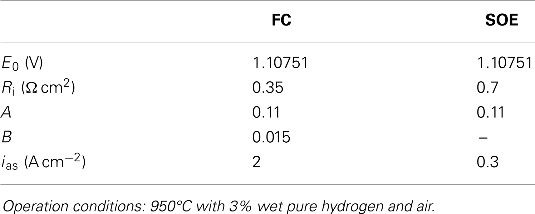
Table 2. Nernst potential and fitted parameters of a microtubular anode-supported cell operated both in SOFC and SOEC mode.
As we have seen, there are several trade-off situations between the parameters described above that hinder cell performance. For example, good cell performance implies low ohmic resistances. Thus, thin electrolyte layers are preferred but we also have to pay attention to electrolyte gas-tightness. Furthermore, current pathways along current collectors can significantly contribute to the ohmic resistance, and they should be as short as possible. Low electrode polarization means a wise choice of the materials involved, in particular, cathode materials whose activity is highly dependent on temperature. Reactants and product diffusion contribute to electrode polarization. Nevertheless, increasing pore volume to improve diffusivity hampers both the mechanical performance and the electronic resistance of electrodes. Furthermore, in order to increase the specific surface area of the catalyzer, we should search for the smaller catalyzer particles, but finer microstructure may give rise to an increase in the tortuosity then deteriorating gas diffusivity. All these factors have to be taken into account when mT-SOFCs are fabricated.
Cell Fabrication
Usually, mT-SOFCs have diameters <10 mm. One of the cell components is used as structural material to support the rest of the component layers. Consequently, mT-SOFCs can be electrolyte-, anode-, or cathode-supported. The cells are fabricated using the typical materials of SOFC technology (Wincewicz and Cooper, 2005; Menzler and Tietz, 2010). Typical materials for the electrolyte are fluorites (YSZ, GDC, and SDC), perovskites (LSGM), or apatites (LSO and LGO). As for anodes, the most frequently used materials are cermets, where the metallic part is typically nickel and the ceramic component is generally the same material as the electrolyte. Finally, LSM, LSCF, LSC (La0.8Sr0.2CoO3), or LSF (La0.8Sr0.2FeO3) are the most frequently used cathode materials. All the acronyms are summarized in Table 3, including other most-used additives in mT-SOFC fabrication, with the electrochemical performance of these materials being critical for cell design and operation conditions. For example, pioneering work on mT-SOFCs was performed on cells supported on YSZ tubes. These electrolyte-supported cells benefit from the outstanding thermo-mechanical performance of YSZ which is also a relatively cheap material, extensively used by the car industry as a part of combustion gas sensors. As YSZ is not a particularly good ionic conductor, a relatively thick electrolyte forces us to operate YSZ-supported cells at temperatures of 900°C and above.
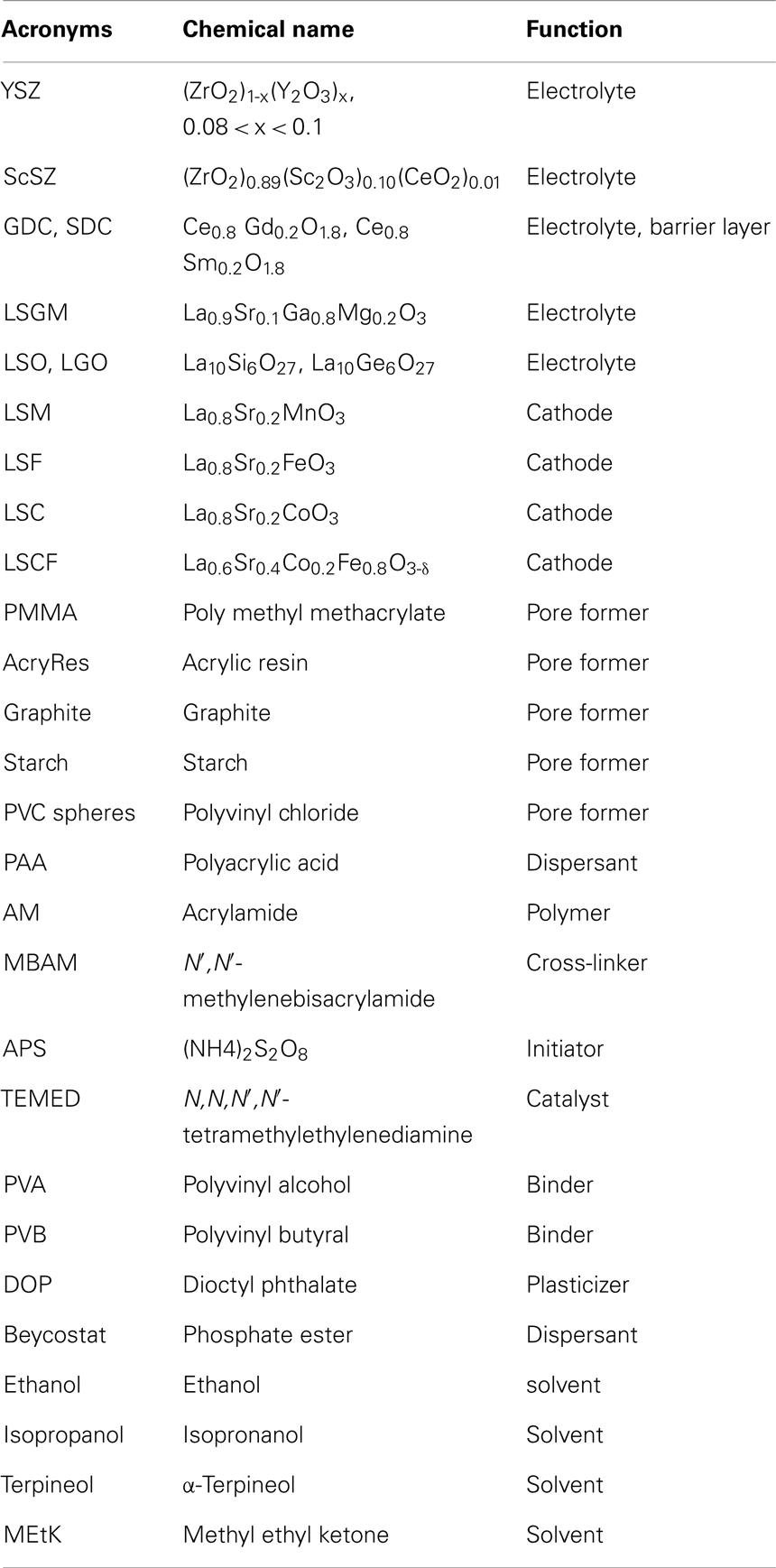
Table 3. Most frequently used components of mT-SOFCs.
This is not the case for electrode-supported cells, where thin electrolyte layers of about 10 μm can be obtained. Anode-supported cells are preferred to cathode-supported cells because the anode materials are much cheaper than cathode materials. The most frequently used SOFC anode is the porous cermet composite of electrolyte and Ni. Higher porosity and lower tortuosity means better gas permeation values. However, high values of pore volume and low values of tortuosity have to be harmonized with mechanical integrity and good resistance to thermal variations. In terms of the total pore volume, gas permeability starts to increase above the percolation limit of 30%, reaching a saturation value at about 50%. A volumetric pore volume around 40%, giving a permeability of about 10−4 mol m−2 s Pa, can ensure a reasonable value for a good anode (Campana et al., 2008). For anode supports, the optimal tortuosity can be between 1 and 20 (Singhal and Kendall, 2003). For example, standard Ni/YSZ anodes are made of a 50/50 volume of Ni/YSZ of solid phase with about 40 vol% open porosity. In order to determine the amount of pore former in the green tube, it is worth remembering that nickel is introduced in the form of NiO. Its subsequent reduction to Ni induces an extra porosity of about 20%.
In addition, the anode has to be a good electronic conductor, which implies Ni particle concentrations well above the percolation threshold. Catalyzer particles should be as small and disperse as possible but resistant to coarsening under operation. The YSZ scaffold helps to keep coarsening under control. A good strategy is to build a double anode consisting of a thick support with coarser microstructure and high gas permeation values in contact with the fuel channel. On this support, a thin anode layer of a few microns in thickness is built. The microstructure of this functional layer is denser and smaller to improve catalytic activity. The electrolyte and cathode layers are deposited on the anode and co-sintered to obtain the ultimate ceramic body. Co-sintering is a delicate process in which all the ceramic components have to match their contractions to avoid cracking or delamination. This is particularly critical in the case of small tubes because of a higher surface area and high curvatures. It is worse in the present case where electrode-supported cells with a dense uncracked thin electrolyte layer have to be produced. In any case, it might be favorable that the outer layer undergoes densification at a slightly lower temperature than the support. Tailoring the density of the green bodies and adjusting sintering temperatures are necessary to get this matching. For example, dilatometer experiments were performed on a NiO/YSZ composite and on YSZ samples of different grain sizes to adjust sintering conditions (Monzón et al., 2014). In fine-grained YSZ, sintering takes place at lower temperatures than in coarser-grained YSZ, but this might not be favorable in terms of contraction matching with the anode.
Fabrication of Support Tubes
mT anode supports are usually fabricated by either extrusion or cold isostatic pressing (CIP) of NiO, YSZ, and pore former powders, but new ceramic processing technologies such as gel casting or the phase inversion method are being incorporated into the field.
Cold isostatic pressing
Cold isostatic pressing is a method of compacting powders into green bodies and near-net shaped in a pressure vessel. The ceramic powder, which has been previously conditioned for the appropriate grain size and shape, is sealed in a flexible mold formed as in the end product, using a ceramic or metallic rod core in the case of tubes. High pressure is then applied up to 400 MPa for few minutes. The demolded green body presents a high and uniform density, resulting in simpler handling and easier machining. As an example in Figure 2 we give the steps for the fabrication of a NiO/YSZ anode tube. The first step consists of powder conditioning to obtain powder grain sizes to a maximum size of about 1–2 μm. Commercial powders may need to be ball milled for this purpose. The components are mixed in the right proportions and after adding pore former and binder (see Table 3 for a listing of the most common pore formers and binders), the powders are introduced into the mold and pressed at RT.
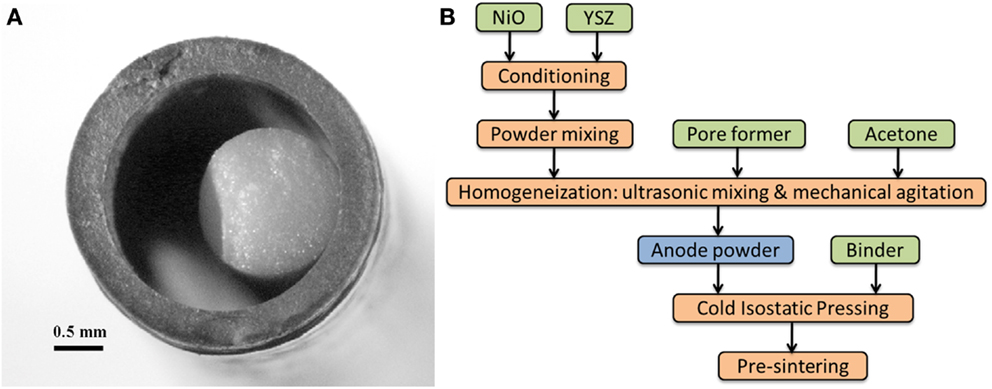
Figure 2. (A) Cross-section of a NiO/YSZ tube fabricated by CIP. (B) CIP production scheme.
The CIP technique is simple, uses small amounts of products, and is relatively quick. It is more appropriate for laboratory scale experiments, for optimization of the final product or for exploring new materials. However, it is difficult to reproduce the shape, size, and other characteristics of the green body exactly, and it is not easily scalable, thus not appropriate for high production rates.
Extrusion
This is about the most frequently used technique for mT production (Du and Sammes, 2004; Lee et al., 2008; Dikwal et al., 2009). As an example, for the fabrication of support tubes by extrusion process, a powder mix of NiO (Hart Materials) and YSZ (Tosoh) powders and corn starch as pore former is used. The binder is polypropylene (supplied by Repsol YPF), paraffin wax (Panreac), and stearic acid (Panreac). Final composition of the anode is Ni:YSZ ratio of 50:50 (in % volume of solid phase), with porosity close to 50%. The feedstock was compounded in a Haake Rheocord 252 mixer with a pair of roller rotor blades at 170°C and 40 rpm (Monzón et al., 2014).
Anode tubes were extruded using a single screw extruder (Haake Polylab) with a home-designed extrusion die connected to the extruder (Jardiel et al., 2009). The ceramic slurry with the plasticizer incorporated is pushed or drawn through a die with the desired annular cross-section at the temperature when the plasticizer induces the easy slipping of the suspension. The suspension is then extruded into an external coagulation bath. The tubes present an excellent surface finish and can be produced on an industrial scale (see Figure 3). The most crucial issue is that of the suspension stability with a solid charge as high as possible to induce large density values of the green tube. Critical extrusion parameters are the screw speed and the temperature profile to obtain a self-sustaining plastic rod. Co-extrusion is a novel procedure for dual layer production, usually anode and electrolyte, which is performed using a dual die. After sintering, the quality of the interface obtained in this case is superior (Othman et al., 2011a).
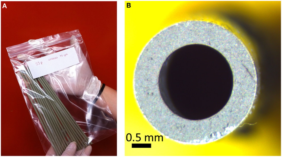
Figure 3. (A) NiO/YSZ tubes produced by extrusion. (B) Cross-section of a tube.
Gel casting
This is a wet technique, which allows shaping of tubes and a fine control of nanometer-sized powders and pore formers avoiding grain agglomeration. The technique involves the preparation of suspensions with polyacrylic acid (PAA) as dispersant, an organic polymer (acrylamide, AM) and a cross-linker [N,N′-methylenebisacrylamide (MBAM)]. After adding the initiator [(NH4)2S2O8, APS] and catalyst [N,N,N′,N′-tetramethylethylenediamine (TEMED)], gel is cast into the mold, then dried under controlled humidity and sintered (Dong et al., 2007; Morales et al., 2012).
Hollow fibers
This is quite a novel and economical design for mT-SOFCs, fabricated using HF supports. The membranes are prepared by an immersion-induced inversion method. The main difference with fibers produced by extrusion is that the HF technique provides good control of the microstructure of the tube that can, for example, be graded from the outside to inside surfaces. In this way, a low porosity anode functional layer can be placed near the electrolyte (outside), whereas a high porosity layer is placed inside, close to the fuel channel. The fibers are very thin, <1 mm in diameter and with a wall of 200 μm in thickness, thereby increasing the specific surface area of the electrodes and increasing the VPD. Details of the preparation of anode HFs can be seen in a recent report (Droushiotis et al., 2009). This technique can also be used to produce dual layers of anode and electrolyte (Othman et al., 2011b). A scheme demonstrating the fabrication process is shown in Figure 4. The overall view (a) and the microstructure of a GDC/NiO–GDC dual layer HF (b) is also shown in this figure.
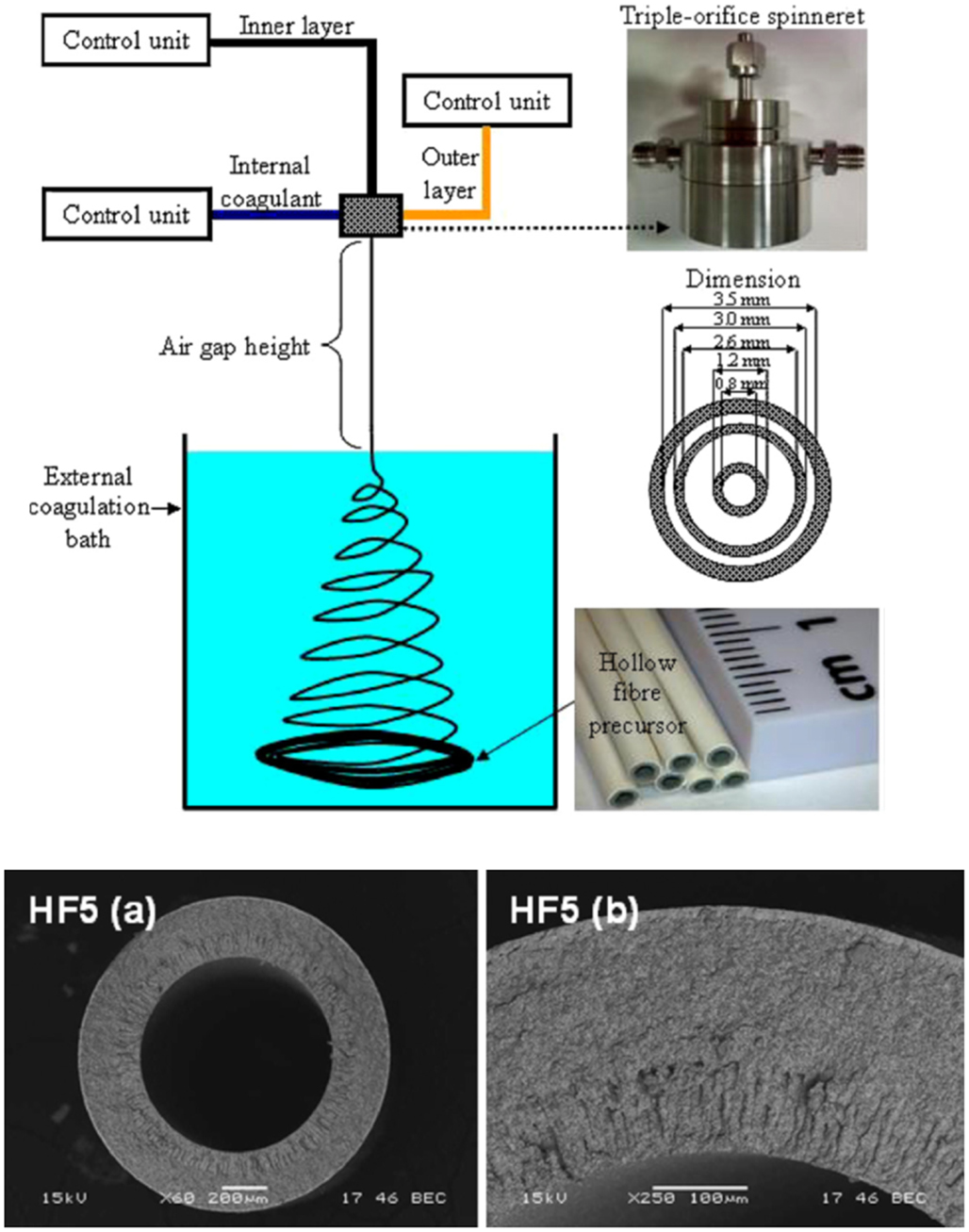
Figure 4. (Above) schematic representation of the phase inversion-based co-extrusion process; (below) SEM images of the (a) overall view and (b) cross-section of the CGO/Ni–CGO dual-layer HF. Reprinted with kind permission from Othman et al. (2011a,b).
Electrolyte and Cathode Fabrication
Prior to electrolyte and cathode thin layer deposition, a dilatometry test has to be performed in order to determine the best co-sintering conditions. Then, a suspension for the electrode deposition is prepared with TZ-8YS powders in an isopropanol ethanol azeotropic mixture, using polyvinyl butyral (PVB) as binder and Beycostat as dispersant agent. For a conventional anode-supported mT-SOFC, the electrolyte is deposited by wet power spraying coating (WPS) or dip-coating. Furthermore, the anode and electrolyte are co-sintered in an air atmosphere. For YSZ-based cells, co-sintering is performed at 1400–1450°C.
Cathode deposition
Then, typical oxygen electrodes such as LSCF or LSM are deposited by dip-coating and sintered at 1150°C in air. In some cases, reactivity between the cathode material and electrolyte, for example, in the case of LSCF and YSZ at sintering temperatures, requires the use of barrier layers, in this case made of a GDC thin film. Wet deposition techniques start with the preparation of the solutions. In general, improving the sintering process requires highly reactive layers made of small-sized particles. On the other hand, highly reactive particles tend to produce agglomerates leading to porous sintered bodies. To overcome this problem, concentrated and stable colloidal suspensions have to be produced. This can be achieved by manipulating the interparticle forces by the use of dispersants. An example of the study of the colloidal stability of GDC powder suspensions prepared for barrier layer fabrication can be found in reference (López-Robledo et al., 2013).
In the case of WPS, the suspension is sprayed over the tube by a computer-controlled aerograph. The thickness of the coating is adjusted by controlling the deposition rate and the solution density. Evaporation of the solvents leaves a thin layer of coating. In the case of dip-coating, the substrate is immersed in the solution of the coating material at constant speed, it remains inside the solution for a while and is then pulled out at constant speed. The speed of withdrawal determines the thickness of the coating. As in the case of WPS, evaporation of the solvents leads to the deposition of the green thin film. Thicknesses of 5–10 μ/dip are usually achieved.
Infiltration Techniques
Infiltration of porous electrodes with precursor metal salt solutions (nitrates), and further calcination is a useful technique for incorporating very fine and well dispersed metal catalyst particles in mT-SOFC anodes. In addition, incorporation of some oxide nanoparticles to the electrode porous structure may also increase the cell performance (Vohs and Gorte, 2009). This is the case of infiltration with GDC nanoparticles that results in increases in output power by a factor of 2, as has been described in conventional Ni–YSZ/YSZ/LSM mT-cells when both anode and cathode are infiltrated with GDC nanoparticles. Power densities as high as 1100 and 770 mW cm−2 have been reported for GDC infiltrated mT-cells fueled with wet H2 and CH4, respectively (Zhang et al., 2009).
Using infiltration techniques, we can also decrease or even eliminate some of the problems encountered when we use conventional co-sintering techniques for cell fabrication. These problems are more frequently observed during the fabrication of the cathode layer and are produced from the chemical instability of the catalyzer or from the reactivity of the catalyzer with other cell components at the firing temperature. As an example of the advantages of the infiltration over the conventional co-sintering fabrication procedures, we report on the case of nickelate cathodes. These compounds are unstable at high temperatures and difficult to use in SOFC fabricated by conventional sintering processes. It has been reported recently that infiltration of nickelate salt precursors followed by calcination avoids high temperature sintering of the nickelate phase with the electrolyte and, as a consequence, prevents their reaction. Figure 5 shows the microstructure of a Nd-nickelate/YSZ composite cathode fabricated by this procedure (Laguna-Bercero et al., 2014). As can be seen, one of the advantages of infiltration is the increased length of TPB compared with the standard cathode, due to the smaller size of the catalyzer particles.
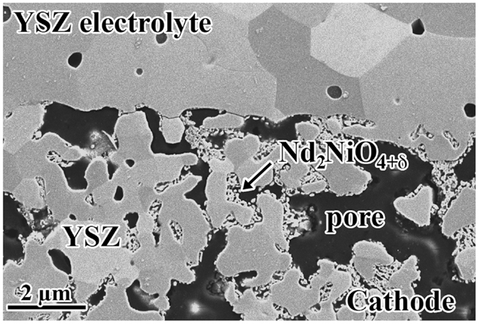
Figure 5. SEM image of a mT-SOFC cathode/electrolyte interface showing ND-nickelate particles infiltrated into porous YSZ.
Using infiltration techniques, it is possible to fabricate mT-cells made of a single monolith, for example, of an YSZ scaffold. In that case, a tube consisting of a more or less symmetrical sequence of porous-dense-porous YSZ layers can be fabricated. The YSZ body is the support for infiltration of anode and cathode materials in the inner and outer porous layers. The method used for the fabrication of these cells has been developed at the University of Alberta (Torabi and Etsell, 2013). This technique secures good interfaces between electrolyte and electrodes, although the main problem remains in the control of the infiltration process for correct catalyzer incorporation.
mT-SOFC Performance and Durability
In Table 4 we summarize the characteristics and performances of some of the mT-SOFCs fabricated in different groups. As can be seen, most realizations are on anode-supported cells, as they include advantages in terms of the low temperature operation, price, and performance. However, anode-supported cells encompass some problems in terms of durability and resistance to accidental oxidation processes.
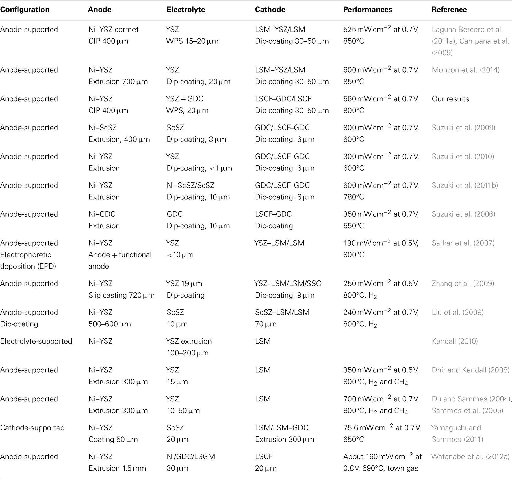
Table 4. Description of cells produced by different groups working in mT-SOFC.
In fact, durability and reliability are crucial aspects for SOFC application and depend on the thermo-chemical and thermo-mechanical compatibility of the cell materials, which also depend on cell processing. Yokokawa et al. (2008) reviewed the fundamental mechanisms behind SOFC durability. In the case of anode-supported cells for portable applications, the dimensional changes associated with redox-cycling are of critical concern for the integrity of the cell (Sarantaridis and Atkinson, 2007). Kendall and Dikwal (2009) performed several cycling studies of anode-supported mT-SOFC (Ni/YSZ–YSZ–LSM/YSZ from Adaptive Materials Inc.), including rapid thermal and redox-cycling studies (Kendall et al., 2007; Howe and Kendall, 2011). They observed an initial drop of about 1% over the first 40 h of operation, and estimated a long-term degradation of <5%/1000 h. Du et al. (2008) also studied the thermal stability of portable mT-SOFCs and stacks. They demonstrated 0% power degradation against thermal cycling for single cells, and also 0% power degradation under load for a period of 1000 h for the stack, assuring that the devices (developed at NanoDynamics Energy) are suitable for portable applications (see Figure 6).
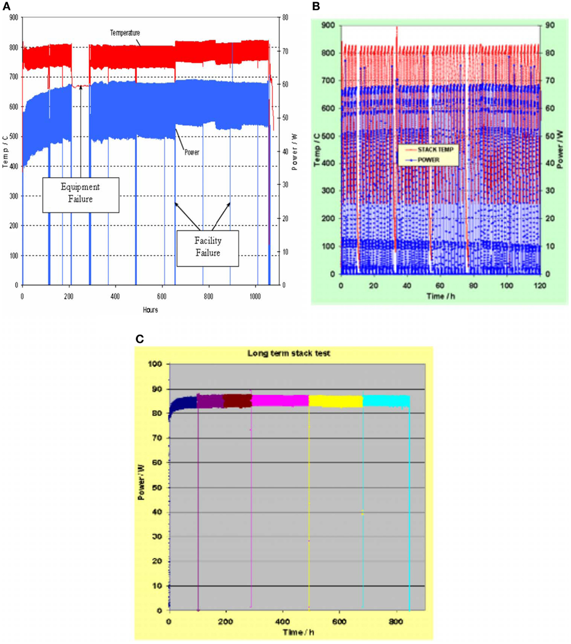
Figure 6. ND energy rev 50 stack 1000 h test (A), 50 thermal cycling test (B), and new Rev 50 stack 845 h test with a higher power output (C). Reprinted with kind permission from Du et al. (2008).
Almutairi et al. (2012) also performed durability studies of different tubes from the integrated-planar solid oxide fuel cell (IP-SOFC) of Rolls Royce Fuel Cell Systems Ltd. The experiments were performed for more than 1200 h at a constant current of 1 A at 900°C. They found an average voltage degradation rate of around 1.5%/1000 h. Recently, a long-term stability study of an anode-supported NiO/YSZ–YSZ–LSM/YSZ microtubular cell has been reported. An initial galvanometric test was performed at 766°C with a density current of 200 mA cm−2. At this temperature, the cell power output at 0.5 V is about 250 mW cm−2 and the ohmic resistance 0.32 Ω cm−2. After an initial period of 325 h, the cell performance remains unchanged. Then, the cell temperature was raised to 873°C, and the current density was increased to 500 mA cm−2 for an additional period of 329 h. The cell power output at 0.5 V was about 600 mW cm−2, and the ohmic resistance was 0.185 Ω cm−2. Several partial re-oxidation events due to disturbances in fuel supply occurred at this stage, but no apparent degradation of the microtubular cell was observed. On the contrary, a small overall increase in the cell output power of about 4%/1000 h after 654 h of fuel cell operation under current load was obtained (Laguna-Bercero et al., 2013).
mT-SOEC Performance
Initial SOEC experiments using mT-SOFC cells were performed by Toshiba Co. Ltd. (Matsunaga et al., 2006). They reported 1.25 V at −0.1 A cm−2 and 700°C. Hashimoto et al. (2009) also reported a microtubular SOEC based on the scandia-stabilized zirconia electrolyte. They showed modest performance of -0.1 A cm−2 at 700°C and an operation voltage of 1.37 V, with an ASR of 4.3 Ω cm2. Highly efficient reversible microtubular cells were reported from our group in collaboration with Imperial College London using Ni–YSZ/YSZ/LSM–YSZ cells, where current densities of -1 A cm−2 using 70% H2O/15% H2/15% N2 as a fuel at 1.3 V and 850°C were reported (Laguna-Bercero et al., 2010). Further experiments confirmed that operation of anode-supported YSZ-based microtubular cells in SOEC mode under high voltages (>1.8 V) produces irreversible degradation of the electrolyte, caused by YSZ electroreduction of the thin electrolyte (Laguna-Bercero et al., 2010, 2011a). Finally, Wang et al. (2010) studied the IT-SOEC range with a Ni–ScSZ/ScSZ/GDC/LSCF cell. They obtained reasonable performances at 650°C (1.32 V at −0.57 A cm−2). Additional SOEC results using mT-SOFCs can be found in the following references (Kato et al., 2009; Wang and Mori, 2010; Jin et al., 2011; Shao et al., 2013). As for planar configuration, HTSE using mT-SOC is still an immature technology. Although the understanding of the structure and electrochemistry of the materials is essential to ensure the durability of future mT devices, the concept of mT-cells for HTSE has been demonstrated and the technology has huge potential.
Final Remarks and Conclusion
The use of hydrogen as an energy carrier requires the implementation of hydrogen infrastructures comprising hydrogen storage and transport. In the meantime, high temperature operating SOFCs may fill the gap as they may use hydrocarbons as a fuel. In general, SOFCs are large and heavy devices which will be mainly used for static applications. On the other hand, mT-SOFCs come into view as an appealing alternative to planar and conventional tubular cells, specifically for low power applications. In general, mT-SOFCs are relatively easy and low-cost to manufacture. In addition, sealing of individual cells can be performed outside the hot cell area, which greatly simplifies cell testing under operation conditions. This makes mT-SOFCs to be a suitable test laboratory for exploratory studies of new SOFC components.
However, there are still some problems to be solved prior to full application of this technology. As for all the SOFC systems, cell operation temperatures lower than the current 800°C are considered necessary. Lowering cell temperature requires implementation not only of new and better ionic conducting materials for electrolytes but also of better cathodes to decrease the electrode overpotentials. In addition, these new materials have to resist the manufacturing processes, being thermally and chemically stable in the presence of the other cell components. Liquid hydrocarbon fuels are optimum for portable applications. However, carbon production at the fuel electrode deteriorates catalyzer activity. Moreover, there are some critical aspects of this cell geometry that should be taken into account. Current collection is challenging in this geometry due to the large distance that electrons must cover from reaction areas to electrical terminals. As metal resistance increases with temperature, high ohmic resistance associated with long current collector metal wires weaken the electrical performance of mT stacks. On the other hand, mass transport limitations inside the narrow tube hinder fuel feeding and product evacuation.
For all these reasons, searching for new SOFC materials and for the improvement of stacks is a very active field of research worldwide. Moreover, HTSE have also opened a novel research area for mT-SOFC devices, including the investigation of other applications such as CO2 electrolysis and co-electrolysis of CO2 and steam. These applications could be of great interest for small scale production of fuel gases in remote locations.
Nevertheless, stack fabrication using mT-SOFCs still demands improving some technical aspects such as the fuel utilization rate and the ohmic losses associated to electrical collection and gas management. New and original device designs are being explored to solve these problems.
In this paper, we give some tutorial information about fabrication, properties, and applications, which may be helpful for those researchers interested in entering the field. The state of the art in mT-research, including the most recent findings, is also reviewed and referred to. Easy fabrication and low-cost investment needed to produce mT-SOFC cells may also be motivating for researchers working in the field of the chemistry of materials, and who are interested in testing these materials under SOFC and SOEC operating conditions using these microtubular devices.
Conflict of Interest Statement
The authors declare that the research was conducted in the absence of any commercial or financial relationships that could be construed as a potential conflict of interest.
Acknowledgments
The authors thank grant MAT2012-30763, financed by the Spanish Government (Ministerio de Economía y Competitividad) and Feder program of the European Community.
References
Almutairi, G., Kendall, K., and Bujalski, W. (2012). Cycling durability studies of IP-SOFC. Int. J. Low Carbon Technol. 7, 63–68. doi: 10.1093/ijlct/ctr020
Atkinson, A., Barnett, S., Gorte, R. J., Irvine, J. T. S., McEvoy, A. J., Mogensen, M., et al. (2004). Advanced anodes for high-temperature fuel cells. Nat. Mater. 3, 17–27. doi:10.1038/nmat1040
Buchinger, G., Hinterreiter, P., Raab, T., Griesser, S., Claassen, R., Claassen, D. P., et al. (2006). Operating microtubular SOFCS with hydrogen chloride and hydrogen sulfide containing fuels and synthetic wood gas. J. Fuel Cell Sci. Technol. 3, 280–283. doi:10.1115/1.2205361
Bujalski, W., Dikwal, C. M., and Kendall, K. (2007). Cycling of three solid oxide fuel cell types. J. Power Sources 171, 96–100. doi:10.1016/j.jpowsour.2007.01.029
Calise, F., Restucccia, G., and Sammes, N. (2011). Experimental analysis of performance degradation of micro-tubular solid oxide fuel cells fed by different fuel mixtures. J. Power Sources 196, 301–312. doi:10.1016/j.jpowsour.2010.06.010
Campana, R., Larrea, A., Merino, R. I., Villarreal, I., and Orera, V. M. (2008). SOFC mini-tubulares basadas en YSZ. Bol. Soc. Esp. Ceram. Vidrio 47, 189–195. doi:10.3989/cyv.2008.v47.i4.173
Campana, R., Merino, R. I., Larrea, A., Villarreal, I., and Orera, V. M. (2009). Fabrication, electrochemical characterization and thermal cycling of anode supported microtubular solid oxide fuel cells. J. Power Sources 192, 120–125. doi:10.1016/j.jpowsour.2008.12.107
Cooley, N. (2009). NexTech materials demonstrates world’s largest SOFC platform. Int. J. Hydrogen Energy 34, 8454. doi:10.1016/j.ijhydene.2009.07.108
de la Torre, R., Avila-Paredes, H. J., and Sglabo, V. M. (2013). Comparative performance analysis of anode-supported micro-tubular SOFCs with different current-collection architectures. Fuel Cells 13, 729–732. doi:10.1002/fuce.201300010
Dhir, A., and Kendall, K. (2008). Microtubular SOFC anode optimisation for direct use on methane. J. Power Sources 181, 297–303. doi:10.1016/j.jpowsour.2007.11.005
Dikwal, C. M., Bujalski, W., and Kendall, K. (2009). The effect of temperature gradients on thermal cycling and isothermal ageing of micro-tubular solid oxide fuel cells. J. Power Sources 193, 241–248. doi:10.1016/j.jpowsour.2009.01.097
Doenitz, W., and Erdle, E. (1985). High-temperature electrolysis of water vapor status of development and perspectives for application. Int. J. Hydrogen Energy 10, 291–295. doi:10.1016/0360-3199(85)90181-8
Dong, D., Gao, J., Liu, X., and Meng, G. (2007). Fabrication of tubular NiO/YSZ anode-support of solid oxide fuel cell by gelcasting. J. Power Sources 165, 217–223. doi:10.1016/j.jpowsour.2006.10.098
Droushiotis, N., Doraswami, U., Kanawka, K., Kelsall, G. H., and Li, K. (2009). Characterization of NiO-yttria stabilised zirconia (YSZ) hollow fibres for use as SOFC anodes. Solid State Ionics. 180, 1091–1099. doi:10.1016/j.ssi.2009.04.004
Du, Y., Finnerty, C., and Jiang, J. (2008). Thermal stability of portable microtubular SOFCs and stacks. J. Electrochem. Soc. 155, B972–B977. doi:10.1149/1.2953590
Du, Y., and Sammes, N. M. (2004). Fabrication and properties of anode-supported tubular solid oxide fuel cells. J. Power Sources 136, 66–71. doi:10.1016/j.jpowsour.2004.05.028
Fu, Q. X., Malibat, C., Zahid, M., Brisse, A., and Gautier, L. (2010). Syngas production via high-temperature steam/CO2 co-electrolysis: an economic assessment. Energy Environ. Sci. 3, 1382–1397. doi:10.1039/c0ee00092b
García-Camprubí, M., and Fueyo, N. (2010). Mass transfer in hydrogen-fed anode-supported SOFCs. Int. J. Hydrogen Energy 35, 11551–11560. doi:10.1016/j.ijhydene.2010.04.085
Graves, C., Ebbesen, S. D., Mogensen, M., and Lackner, K. S. (2011). Sustainable hydrocarbon fuels by recycling CO2 and H2O with renewable or nuclear energy. Renew. Sustain. Energ. Rev. 15, 1–23. doi:10.1016/j.rser.2010.07.014
Hashimoto, S., Liu, Y., Mori, M., Funashashi, Y., and Fujishiro, Y. (2009). Study of steam electrolysis using a microtubular ceramic reactor. Int. J. Hydrogen Energy 34, 1159–1165. doi:10.1016/j.ijhydene.2008.11.037
Howe, K., and Kendall, K. (2011). Transient performance of micro-tubular solid oxide fuel cells and stacks. ECS Trans. 35, 419–423. doi:10.1149/1.3570017
Howe, K. S., Thompson, G. J., and Kendall, K. (2011). Micro-tubular solid oxide fuel cells and stacks. J. Power Sources 196, 1677–1686. doi:10.1016/j.jpowsour.2010.09.043
Huang, H., Nakamura, M., Su, P., Fasching, R., Saito, Y., and Prinz, F. (2007). High-performance ultrathin solid oxide fuel cells for low-temperature operation. J. Electrochem. Soc. 154, B20–B24. doi:10.1149/1.2372592
Isenberg, A. O. (1981). Energy conversion via solid oxide electrolyte electrochemical cells at high temperatures. Solid State Ionics. 3-4, 431–437. doi:10.1016/0167-2738(81)90127-2
Jardiel, T., Levenfeld, B., Jimenez, R., and Varez, A. (2009). Fabrication of 8-YSZ thin-wall tubes by powder extrusion moulding for SOFC electrolytes. Ceram. Int. 35, 2329e35. doi:10.1016/j.ceramint.2009.01.008
Jensen, S. H., Sun, X., Ebbensen, S. D., Knibbe, R., and Mogensen, M. (2010). Hydrogen and synthetic fuel production using pressurized solid oxide electrolysis cells. Int. J. Hydrogen Energy 35, 9544–9549. doi:10.1016/j.ijhydene.2010.06.065
Jin, C., Yang, C. H., and Chen, F. L. (2011). Novel micro-tubular high temperature solid oxyde electrolysis cells. ECS Trans. 35, 2987–2995. doi:10.1149/1.3570299
Kanawka, K., Othman, M. H. D., Droushiotis, N., Wu, Z., Kelsall, G., and Li, K. (2011). NI/NI-YSZ current collector/anode dual layer hollow fibers for micro-tubular solid oxide fuel cells. Fuel Cells 11, 690–696. doi:10.1002/fuce.201000174
Kato, T., Sakaki, N., Negishi, A., Honda, T., Nguyen, L., and Tanaka, Y. (2009). Development of tubular solid oxide electrolysis cells for hydrogen production. ECS Trans. 25, 1015. doi:10.1149/1.3205626
Kendall, K. (1992). “Novel ceramic designs for fuel cells,” in Proceedings of the International Forum on Fine Ceramics (Nagoya: Japan Fine Ceramics Centre), 143–148.
Kendall, K. (2010). Progress in microtubular solid oxide fuel cells. Int. J. Appl. Ceram. Technol. 7, 1–9. doi:10.1111/j.1744-7402.2008.02350.x
Kendall, K., and Dikwal, C. M. (2009). Cycling studies of microtubular SOFCs. ECS Trans. 25, 899–906. doi:10.1149/1.3205610
Kendall, K., Dikwal, C. M., and Bujalski, W. (2007). Comparative analysis of thermal and redox cycling for microtubular SOFCs. ECS Trans. 7, 1521–1526. doi:10.1149/1.2729257
Kendall, K., and Meadowcroft, A. (2013). Improved ceramics leading to microtubular solid oxide fuel cells (mSOFCs). Int. J. Hydrogen Energy 38, 1725–1730. doi:10.1016/j.ijhydene.2012.08.094
Kendall, K., Minh, N. Q., and Singhal, S. C. (2003). “Cell and stacks designs, Chapter 8,” in High Temperature Solid Oxide Fuel Cells: Fundamentals, Design and Applications. eds S. C. Singhal and K. Kendall (Oxford: Elsevier), 197–225.
Kendall, K., and Sales, G. (1994). “A rapid heating ceramic fuel cell,” in Proceedings of the 2nd International Conference on Ceramics in Energy Applications. eds S. C. Singhal and K. Kendall (London: Institute of Energy), 55–63.
Kendall, M. (1993). Tubular Cells: A Study of a Tubular SOFC. Final Year Project Report, No. 1-86. Middlesex University, London.
Kim, J.-W., Virkar, A. V., Fung, K.-Z., Mehta, K., and Singhal, S. C. (1999). Polarization effects in intermediate temperature, anode-supported solid oxide fuel cells. J. Electrochem. Soc. 146, 69. doi:10.1021/am5003662
Laguna-Bercero, M. A. (2012). Recent advances in high temperature electrolysis using solid oxide fuel cells: a review. J. Power Sources 203, 4–16. doi:10.1016/j.jpowsour.2011.12.019
Laguna-Bercero, M. A., Campana, R., Larrea, A., Kilner, J. A., and Orera, V. M. (2010). Steam electrolysis using a microtubular solid oxide fuel cell. J. Electrochem. Soc. 6, B852–B855. doi:10.1149/1.3332832
Laguna-Bercero, M. A., Campana, R., Larrea, A., Kilner, J. A., and Orera, V. M. (2011a). Performance and aging of microtubular YSZ-based solid oxide regenerative fuel cells. Fuel Cells 11, 116–123. doi:10.1002/fuce.201000069
Laguna-Bercero, M. A., Campana, R., Larrea, A., Kilner, J. A., and Orera, V. M. (2011b). Electrolyte degradation in anode supported microtubular yttria stabilized zirconia-based solid oxide steam electrolysis cells at high voltages of operation. J. Power Sources 196, 8942–8947. doi:10.1016/j.jpowsour.2011.01.015
Laguna-Bercero, M. A., Férriz, A., Larrea, A., Correas, L., and Orera, V. M. (2013). Long-term stability studies of anode-supported microtubular solid oxide fuel cells. Fuel Cells 13, 1116–1122. doi:10.1002/fuce.201300063
Laguna-Bercero, M. A., Hanifi, A. R., Monzón, H., Cunningham, J., Etsell, T. H., and Sarkar, P. (2014). High performance of microtubular solid oxide fuel cells using Nd2NiO4+δ-based composite cathodes. J. Mater. Chem. A. doi:10.1039/C4TA00665H
Lamp, P., Tachtler, J., Finkenwirth, O., Mukerjee, S., and Shaffer, S. (2003). Development of an auxiliary power unit with solid oxide fuel cells for automotive applications. Fuel Cells 3, 146–152. doi:10.1002/fuce.200332107
Lang, M., Auer, C., Eisman, A., Szabo, P., and Wagner, N. (2008). Investigation of solid oxide fuel cell short stacks for mobile applications by electrochemical impedance spectroscopy. Electrochim. Acta 53, 7509–7513. doi:10.1016/j.electacta.2008.04.047
Larrea, A., Sola, D., Laguna-Bercero, M. A., Peña, J. I., Merino, R. I., and Orera, V. M. (2011). Self-supporting thin yttria-stabilised zirconia electrolytes for solid oxide fuel cells prepared by laser machining. J. Electrochem. Soc. 158, B1193–B1197. doi:10.1149/1.3619759
Lawlor, V. (2013). Review of the micro-tubular solid oxide fuel cell (part II: cell design issues and research activities). J. Power Sources 240, 421–441. doi:10.1016/j.jpowsour.2013.03.191
Lawlor, V., Griesser, S., Buchinger, G., Olabi, A. G., Cordiner, S., and Meissner, D. (2009). Review of the micro-tubular solid oxide fuel cell: part I. Stack design issues and research activities. J. Power Sources 193, 387–399. doi:10.1016/j.jpowsour.2009.02.085
Lee, S.-B., Lim, T.-H., Song, R.-H., Shin, D.-R., and Dong, S.-K. (2008). Development of a 700 W anode-supported micro-tubular SOFC stack for APU applications. Int. J. Hydrogen Energy 33, 2330–2336. doi:10.1016/j.ijhydene.2008.02.034
Liu, R. Z., Wang, S. R., Bo Huang, J. H., Zhao, C. H., Li, J. L., Wang, Z. R., et al. (2009). Dip-coating and co-sintering technologies for fabricating tubular solid oxide fuel cells. J. Solid State Electrochem. 13, 1905–1911. doi:10.1007/s10008-008-0752-7
López-Robledo, M. J., Silva-Treviño, J., Molina, T., and Moreno, R. (2013). Colloidal stability of gadolinium-doped ceria powder in aqueous and non-aqueous media. J. Eur. Ceram. Soc. 33, 297–303. doi:10.1016/j.jeurceramsoc.2012.08.027
Martínez-Frias, J., Pham, A. Q., and Aceves, S. M. (2003). A natural gas-assisted steam electrolyzer for high-efficiency production of hydrogen. Int. J. Hydrogen Energy 28, 483–490. doi:10.1016/S0360-3199(02)00135-0
Matsunaga, K., Hoashi, E., Fujiwara, S., Yoshino, M., Ogawa, T., and Kasai, S. (2006). “Hydrogen production system with high temperature electrolysis for nuclear power plant,” in Proceedings of ICAPP06 (Reno, NV: Curran Associates, Inc.), 4–8.
Menzler, N. H., and Tietz, F. (2010). Materials and manufacturing technologies for solid oxide fuel cells. J. Mater. Sci. 45, 3109–3135. doi:10.1007/s10853-010-4279-9
Monzón, H., and Laguna-Bercero, M. A. (2012). Redox-cycling studies of anode-supported microtubular solid oxide fuel cells. Int. J. Hydrogen Energy 37, 7262–7270. doi:10.1016/j.ijhydene.2011.10.026
Monzón, H., Laguna-Bercero, M. A., Larrea, A., Arias, B. I., Várez, A., and Levenfeld, B. (2014). Design of industrially scalable microtubular solid oxide fuel cells based on an extruded support. Int. J. Hydrogen Energy 39, 5470–5476. doi:10.1016/j.ijhydene.2014.01.010
Morales, M., Navarro, M. E., Capdevila, X. G., Roa, J. J., and Segarra, M. (2012). Processing of graded anode-supported micro-tubular SOFCs based on samaria-doped ceria via gel-casting and spray-coating. Ceram. Int. 38, 3713–3722. doi:10.1016/j.ceramint.2012.01.015
Mori, M., Liu, Y., and Itoh, T. (2009). La0.6Sr0.4Co0.2Fe0.8O3-δ current collectors via Ag infiltration for microtubular solid oxide fuel cells with intermediate temperature operation. J. Electrochem. Soc. 156, B1182–B1187. doi:10.1149/1.3184149
Orera, A., and Slater, P. R. (2010). New chemical systems for solid oxide fuel cells. Chem. Mater. 22, 675–690. doi:10.1021/cm902687z
Othman, M. H. D., Droushiotis, N., Wu, Z., Kelsall, G., and Li, K. (2011a). High-performance, anode-supported, microtubular SOFC prepared from single-step-fabricated, dual-layer hollow fibers. Adv. Mater. 23, 2480–2483. doi:10.1002/adma.201100194
Othman, M. H. D., Droushiotis, N., Wu, Z., Kelsall, G., and Li, K. (2011b). Novel fabrication technique of hollow fibre support for micro-tubular solid oxide fuel cells. J. Power Sources 196, 5035–5044. doi:10.1016/j.jpowsour.2011.02.006
Pihlatie, M., Kaiser, A., and Mogensen, M. (2009). Redox stability of SOFC: thermal analysis of Ni-YSZ composites. Solid State Ionics. 180, 1100–1112. doi:10.1016/j.ssi.2009.04.011
Sammes, N. M., and Du, Y. (2003). The mechanical properties of tubular solid oxide fuel cells. J. Mater. Sci. 38, 4811–4816. doi:10.1023/B:JMSC.0000004400.95156.dc
Sammes, N. M., Du, Y., and Bove, R. (2005). Design and fabrication of a 100 W anode supported microtubular SOFC stack. J. Power Sources 145, 428–434. doi:10.1016/j.jpowsour.2005.01.079
Sarantaridis, D., and Atkinson, A. (2007). Redox cycling of NI-based solid oxide fuel cell anodes: a review. Fuel Cells 3, 246–258. doi:10.1002/fuce.200600028
Sarkar, P., Yamarte, L., Rho, H., and Johanson, L. (2007). Anode-supported tubular micro-solid oxide fuel cell. Int. J. Appl. Ceram. Technol. 4, 103–108. doi:10.1111/j.1744-7402.2007.02129.x
Serincan, M. F., Pasaogullari, U., and Sammes, N. M. (2009). Effects of operating conditions on the performance of a micro-tubular solid oxide fuel cell (SOFC). J. Power Sources 192, 414–422. doi:10.1016/j.jpowsour.2009.03.049
Shao, L., Qian, J., Ye, X., and Wen, T. (2013). Optimization of the electrode-supported tubular solid oxide cells for application on fuel cell and steam electrolysis. Int. J. Hydrogen Energy 38, 4272–4280. doi:10.1016/j.ijhydene.2012.12.144
Shao, Z., and Haile, S. M. (2004). A high-performance cathode for the next generation of solid-oxide fuel cells. Nature 431, 170–173. doi:10.1038/nature02863
Singhal, S. C. (2002). Solid oxide fuel cells for stationary, mobile, and military applications. Solid State Ionics. 15, 405–410. doi:10.1016/S0167-2738(02)00349-1
Singhal, S. C., and Kendall, K. (2003). High Temperature SOFCs: Fundamentals, Design and Applications. Oxford: Elsevier.
Suzuki, T., Hasan, Z., Funahashi, Y., Yamaguchi, T., Fujishiro, Y., and Awano, M. (2009). Impact of anode microstructure on solid oxide fuel cells. Science 325, 852–855. doi:10.1126/science.1176404
Suzuki, T., Hasan, Z., Yamaguchi, T., Fujishiro, Y., Awano, M., and Sammes, N. (2010). Fabrication of micro-tubular solid oxide fuel cells with a single-grain-thick yttria stabilized zirconia electrolyte. J. Power Sources 195, 7825–7828. doi:10.1016/j.jpowsour.2009.11.149
Suzuki, T., Liang, B., Hamamoto, K., Yamaguchi, T., Fujishiro, Y., and Awano, M. (2011a). Development of bi-metal anode microtubular supports for solid oxide fuel cells. J. Fuel Cell Sci. Technol. 8, 61013–61067. doi:10.1115/1.4004467
Suzuki, T., Sugihara, S., Hamamoto, K., Yamaguchi, T., and Fujishiro, Y. (2011b). Energy efficiency of a microtubular solid-oxide fuel cell. J. Power Sources 196, 5485–5489. doi:10.1016/j.jpowsour.2011.02.052
Suzuki, T., Yamaguchi, T., Fujishiro, Y., and Awano, M. (2006). Fabrication and characterization of micro tubular SOFCs for operation in the intermediate temperature. J. Power Sources 160, 73–77. doi:10.1016/j.jpowsour.2006.01.037
Tai, L. W., Nasrallah, M. M., Anderson, H. U., and Sparlin, D. M. (1995). Structure and electrical properties of La1-xSrxCo1-yFeyO3. Part 1. The system La0.8Sr0.2Co1-yFeyO3. Part 2. The system La1-xSrxCo0.2Fe0.8O3. Solid State Ionics 76, 259–283.
Tiez, F., Haanappel, V. A. C., Mai, A., Mertens, J., and Stöver, D. (2006). Performance of LSCF cathodes in cell tests. J. Power Sourc. 156, 20–22. doi:10.1016/j.jpowsour.2005.08.015
Torabi, A., and Etsell, T. H. (2013). Electrochemical behavior of solid oxide fuel cell anodes based on infiltration of Y-doped SrTiO3. J. Power Sources 225, 51–59. doi:10.1016/j.jpowsour.2012.09.109
Torabi, A., Hanifi, A. R., Etsell, T. H., and Sarkar, P. (2012). Effects of porous support microstructure on performance of infiltrated electrodes in solid oxide fuel cells. J. Electrochem. Soc. 159, B201–B210. doi:10.1149/2.068202jes
Vohs, J. M., and Gorte, R. J. (2009). High-performance SOFC cathodes prepared by infiltration. Adv. Mater. 21, 943–956. doi:10.1002/adma.200802428
Wang, C., Xin, X., Xu, Y., Ye, X., Yu, L., Wang, S., et al. (2011). Performance of a novel La(Sr)MnO3-Pd composite current collector for solid oxide fuel cell cathode. J. Power Sources 196, 3841–3845. doi:10.1016/j.jpowsour.2010.12.099
Wang, W. G., and Mogensen, M. (2005). High-performance lanthanum-ferrite-based cathode for SOFC. Solid State Ionics. 176, 457–462. doi:10.1016/j.ssi.2004.09.007
Wang, Z., and Mori, M. (2010). Intermediate-temperature micro-tubular ceramic reactor using AG for current collecting. Electrochemistry 78, 601–605. doi:10.5796/electrochemistry.78.601
Wang, Z., Mori, M., and Araki, T. (2010). Steam electrolysis performance of intermediate-temperature solid oxide electrolysis cell and efficiency of hydrogen production system at 300 Nm3 h-1. Int. J. Hydrogen Energy 5, 4451–4458. doi:10.1016/j.ijhydene.2010.02.058
Watanabe, N., Ooe, T., Akagi, Y., and Ishihara, T. (2012a). Estimation of heat generation rate in solid oxide fuel cell module from single cell performance and module performance based on impedance analysis. Int. J. Hydrogen Energy 37, 8562–8571. doi:10.1016/j.ijhydene.2012.02.059
Watanabe, N., Ooe, T., and Ishihara, T. (2012b). Design of thermal self supported 700 class, solid oxide fuel cell module using, LSGM thin film micro tubular cells. J. Power Sources 199, 117–123. doi:10.1016/j.jpowsour.2011.10.071
Wincewicz, K. C., and Cooper, J. S. (2005). Taxonomies of SOFC material and manufacturing alternatives. J. Power Sources 140, 280–296. doi:10.1016/j.jpowsour.2004.08.032
Yamaguchi, T., and Sammes, N. (2011). Anode performance control of microtubular SOFC via wet coating method. Int. J. Hydrogen Energy 36, 7656–7660. doi:10.1016/j.ijhydene.2011.03.125
Yang, L., Wang, S., Blinn, K., Liu, M., Liu, Z., Cheng, Z., et al. (2009). Enhanced sulfur and coking tolerance of a mixed ion conductor for SOFCs: BaZr0.1Ce0.7Y0.2-xYbxO3-δ. Science 326, 126–129. doi:10.1126/science.1174811
Yokokawa, H., Tu, H., Iwanschitz, B., and Mai, A. (2008). Fundamental mechanisms limiting solid oxide fuel cell durability. J. Power Sources 182, 400–412. doi:10.1016/j.jpowsour.2008.02.016
Zhang, L., He, H. Q., Kwek, W. R., Ma, J., Tang, E. H., and Jiang, S. P. (2009). Fabrication and characterization of anode-supported tubular solid-oxide fuel cells by slip casting and dip coating techniques. J. Am. Ceram. Soc. 92, 302–310. doi:10.1111/j.1551-2916.2008.02852.x
Keywords: SOFC, SOEC, microtubular, YSZ, portable application
Citation: Orera VM, Laguna-Bercero MA and Larrea A (2014) Fabrication methods and performance in fuel cell and steam electrolysis operation modes of small tubular solid oxide fuel cells: a review. Front. Energy Res. 2:22. doi: 10.3389/fenrg.2014.00022
Received: 07 January 2014; Accepted: 04 June 2014;
Published online: 25 June 2014.
Edited by:
Reginaldo Muccillo, Energy and Nuclear Research Institute, BrazilReviewed by:
Dachamir Hotza, Federal University of Santa Catarina, BrazilSukhvinder P. S. Badwal, Commonwealth Scientific and Industrial Research Organisation, Australia
Copyright: © 2014 Orera, Laguna-Bercero and Larrea. This is an open-access article distributed under the terms of the Creative Commons Attribution License (CC BY). The use, distribution or reproduction in other forums is permitted, provided the original author(s) or licensor are credited and that the original publication in this journal is cited, in accordance with accepted academic practice. No use, distribution or reproduction is permitted which does not comply with these terms.
*Correspondence: Victor M. Orera, CSIC-Universidad de Zaragoza, C/Pedro Cerbuna 10, Zaragoza 50009, Spain e-mail: orera@unizar.es