Numerical Simulation of Flow and Heat Transfer Characteristics of CuO-Water Nanofluids in a Flat Tube
 Luchao She
 Guangming Fan
- Fundamental Science on Nuclear and Simulation Technology Laboratory, Harbin Engineering University, Harbin, China
In this paper, water and CuO-water nanofluids are selected as working fluids. The characteristics of fluid flow and heat transfer in a heat transfer tube are analyzed by means of numerical simulation. The effect of nanofluid concentration on the flow and heat transfer characteristics of the flat tube under the condition with a Reynolds number of 6,000~10,000 is analyzed and compared with that of the circular tube. The results show that the addition of nanoparticles in the nanofluid has little effect on the velocity and temperature distribution in the flow channel. With the increase of nanofluid concentration, the heat transfer coefficient and flow resistance of the fluid increased. And the comprehensive evaluation factor was 2.51~3.29, which had the effect of enhancing heat exchange. There is a similar trend in the same concentration with different Reynolds numbers. Compared with the circular tube, the nanofluid has a better ability to enhance heat transfer when it flows in the flat tube. Under conditions with the same fluid concentration, the effect of the application of the nanofluids on the flat tube is better.
Introduction
Nanoparticles are particles in the 1–100 nm, between the microscopic system and macroscopic system, and consist of a group of few atoms or molecules (Choi, 1995). Conventional fluids have poor thermal conductivity. An effective way to improve the heat transfer performance of conventional fluids is to suspend fine solids, such as metals and non-metallic particles. Nanofluids are fluids that add nanoparticles with diameters <100 nm in a conventional fluid (Ganvir et al., 2016). The main objective of the application of nanofluids is to achieve the highest thermal conductivity at the lowest possible concentration of nanoparticles. Due to the molecular chain behavior of nanofluids, the suitable dispersed nanoparticles in the base liquid have the advantages of high thermal conductivity, microchannel cooling, no blockage, reducing erosion probability, and increasing pump power (Solangi et al., 2015). Due to the effect of their small size, the coefficient of resistance is not increased significantly as the coefficient of fluid heat transfer increases. And this makes the nanofluid heat transfer technology become a hot research topic in the field of thermal science in recent years. The application of nanofluid in shell-and-tube heat exchanger can increase the heat transfer performance of the tube, without causing large resistance loss, wear, blockage and other undesirable consequences (Eastman and Choi, 2001). This characteristic endows the nanofluids with a wide application prospect in the field of enhanced heat transfer and a potential application in nuclear engineering. Heat exchanger elements are important parts of heat exchangers, and the main form of them is a variety of heat transfer tubes. In recent years, many new heat transfer tubes have been developed to meet the requirements of high efficiency and compact heat exchanger, and the flat tube is one of them. Compared with the circular tube, the flat tube has a higher ratio of surface area and flow area, which can enhance the heat transfer rate and improve the efficiency of the heat exchanger. Moreover, the volume of the flat tube is relatively small, which makes the compact of the heat exchanger greatly improved. Therefore, it is necessary to study the flow and heat transfer performance of the nanofluid in a flat tube.
In recent years, various aspects of nanotechnology have been described as emphasizing applications in energy systems, such as nuclear energy, geothermal energy, and solar energy (Banerjee, 2017). In previous studies, nanofluids have been used as working fluids in the plate heat exchangers (Kumar et al., 2015), micro-channel heat exchangers (Qiang and Yi-Min, 2004; Hwang et al., 2009; Liu and Yu, 2010), Serpentine heat exchanger (Khoshvaght-Aliabadi et al., 2016). However, the application of flat tube heat exchanger is mainly based on experimental research (Li and Xuan, 2002; Wen and Ding, 2004; Chen et al., 2013; Ji et al., 2014), while numerical simulations are relatively rare. It is concluded that under the condition with the same Reynolds number, the convective heat transfer coefficient of the nanofluid in the flat tube is larger than that of the pure liquid, and increases with the increase of the particle volume fraction. Interestingly, the resistance coefficient of the nanofluid is not obviously increased. The addition of nanoparticles under laminar flow conditions has improved the heat transfer andpressure loss of the base fluids in all the flat tubes under various Reynolds numbers and temperatures (Zhao et al., 2016). All these conclusions are obtained under the condition of small channel or laminar flow, and the results are relatively few in the turbulent conditions of ordinary flat tubes. In this paper, the flow and heat transfer characteristics of a flat tube under conditions with different Reynolds number are numerically simulated with CuO-water nanoparticles as working fluids.
Computational Model
In order to analyze the comprehensive heat transfer capacity of flat tube, the geometrical model of flat tube and circular tube is established, and its cross-section is shown in Figure 1. The model includes two parts of tube wall and fluid. In order to ensure the accuracy of the final simulation result and prevent the effect of entrance on the calculation result, the stable section of the heat transfer tube is set up respectively in the model (Figure 2). The geometrical dimensions of the heat transfer tube are shown in Table 1.
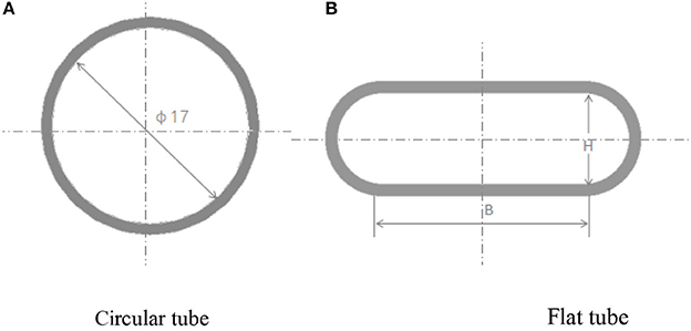
Figure 1. Schematic diagram.
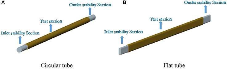
Figure 2. Calculation model.
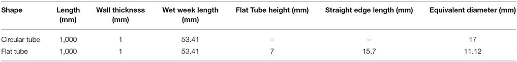
Table 1. Geometrical parameters of heat transfer tube.
In this paper, the Workbench software is used to divide the hexahedral structured grids by sweep division. The three-stage fluid parts have the same setting. The minimum mesh size of the source surface is 0.8 mm, and the boundary layer grid is refined, and the solid wall surface is set to 5 nodes 4-layer grid. The final grid form is shown in Figure 3.
Figure 3. Grid partition.
Grid quality measurement method is skewness, in general, the value <0.7 is acceptable. As shown in Figure 4, the maximum skewness number of the flat tube meshes is 0.5, and the circular tube is 0.55, both within the allowable range.
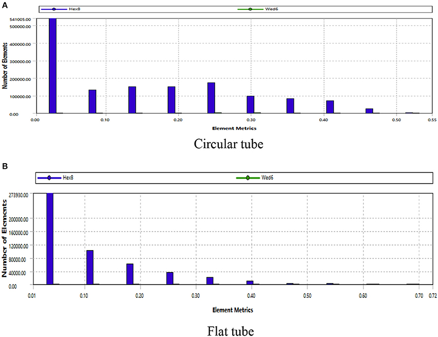
Figure 4. Grid quality.
In this paper, the correlation between the heat transfer coefficient and the friction coefficient is also verified. The heat transfer coefficient is derived from analog data, and the calculation formula of friction coefficient is as follows:
Type: ΔP is the tubeline pressure drop; L is the test section length; d is equivalent diameter of the heat transfer tube; ρ is fluid density; u is the fluid Velocity.
As shown in Figure 5, when the number of tube meshes reaches 370,000, the average fluid heat transfer coefficient and the tube friction coefficient have no significant change, that is, 370,000 is the minimum number of meshes that can guarantee the accuracy of the simulation calculation. Therefore, in this paper, the circular tubes are calculated numerically by using 370,000 mesh grids. Same as the circular tube, the number of flat tube grids is 570,000.
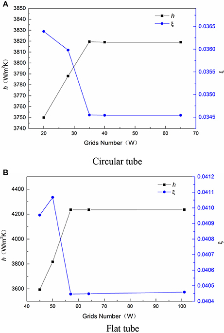
Figure 5. Grids Independent verification.
In the setting of boundary conditions, the inlet of the heat transfer tube adopts the velocity boundary, and the size is determined by Reynolds number at the temperature of 293 K. The outlet is provided with a pressure exit border of 0 Pa, which is discharged into the vacuum. The tube wall is provided with no slip boundary condition, and the heating wall is provided with constant wall temperature boundary of 400 K. At the same time, the fluid surface of the stable section and the end surface of the tube are adiabatic conditions, and the SST model is chosen.
It is known from the literature (Rao et al., 2003; Wang et al., 2003) that the stability of the fluid is the highest when the particle size of nanoparticles is 20 nm. Therefore, the concentrations of CuO particles in water are 0.05, 0.1, and 0.15 with particle size of 20 nm. The thermal conductivity and other physical parameters of the nano-flow vary with the concentration of nanoparticles, as shown in Table 2.
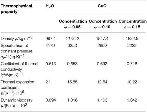
Table 2. Water and concentration of nanofluids physical parameters (Sun et al., 2015).
Simulation Results Analysis
Heat Transfer Characteristics Analysis
The change of heat transfer coefficient with Reynolds number in the tube is shown in Figure 6. The greater the concentration of the nanoparticles in the fluid, the greater the average heat transfer coefficient of the fluid. In the case with Reynolds number of 6,000, the heat transfer coefficient of nanofluid relative to water increased by 5.24, 9.4, and 12.63%, respectively. This is because the thermal conductivity of metal particles is much higher than that of water. Because of the presence of the boundary layer at the wall, the addition of appropriate amount of metal nanoparticles in water can reduce the heat transfer heat resistance while increasing the thermal conductivity, thus it can significantly improve the heat transfer performance of the fluid near the wall and increase the coefficient of heat exchange. At the same time, the average heat transfer coefficient h of water and the concentration of nanometer fluid in the flat tube is 11.38 ~ 13.3% larger than that of the circular tube. This is due to the heat transfer intensity of the main heating boundary layer thickness, under certain temperature conditions, the thinner the thickness of the flow boundary layer, the thinner the thickness of the hot boundary layer, and the greater the heat transfer intensity of the fluid. According to Yuan-Xun (2005), the formula for calculating the thickness of flow boundary layer is:
Therefore, under the same section circumference of the heat transfer tube, the equivalent diameter of the flat tube is smaller, that is, the thickness of the flow boundary layer is thinner and the heat transfer effect is stronger under the same Reynolds number.
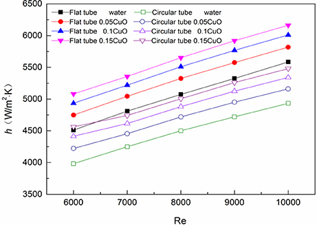
Figure 6. Change of heat transfer coefficient with Reynolds number.
Figure 7 shows the change of heat transfer coefficient of each concentration of nanofluids in the two heat tubes in relation to the increase of water and the Reynolds number. It can be seen from the diagram that the ability of the nanofluid to enhance the heat transfer coefficient is stronger in the circular tube. This is because the boundary layer in the flat tube is thinner than that of the circular tube, and it is known from above that the nanofluid can significantly enhance the heat transfer capability of the boundary layer, so the heat transfer coefficient of the thicker circular tube in the boundary layer increases greatly. This phenomenon is most obvious at Re = 6,000, and the heat transfer coefficient of nanofluid in the flat tube is up to 12.63%, while the maximum of the circular tube increases by 14.57%.
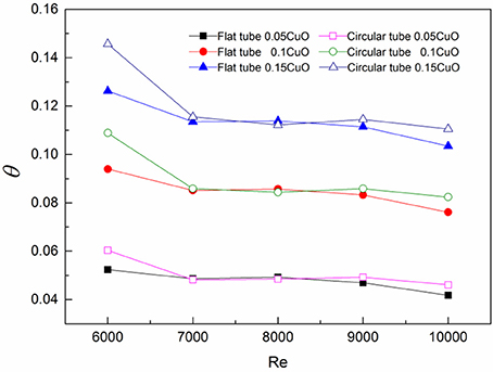
Figure 7. Change of heat transfer coefficient increase with Reynolds number.
In order to understand the temperature change in the heat transfer tube, the axial and radial temperature distributions have been analyzed, and the temperature distributions of the average temperature along the axial and radial directions of each section of the two heat transfer tubes are given. As shown in Figure 8, the temperature along the axial direction of the two heat transfer tubes is basically the same. However, in the same condition, the average temperature of the flat tube along the axial section is higher than that of the corresponding circular tube, and reaches to the maximum value at the outlet section. The temperature growth rate of the flat tube is also higher than that of the circular tube, and at the outlet section, the fluid concentrations are 5.41, 5.62, 5.74, and 5.8%, respectively.
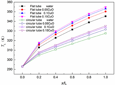
Figure 8. Temperature comparison of two tubes along axial section.
As shown in Figure 9, the trend of temperature variation along the radial direction in the circular tube is basically consistent with that of the flat tube. Though the temperature of the point on the cross-section of the circular tube is lower than that of the corresponding point in the flat tube, the temperature gradient in the near wall of the circular tube is greater. This is because the heat transfer coefficient of the flat tube is larger, its absorption of heat is more so the temperature is higher, but the circular tube boundary layer is thicker, the temperature grows faster, so the temperature gradient of the circular tube is larger.
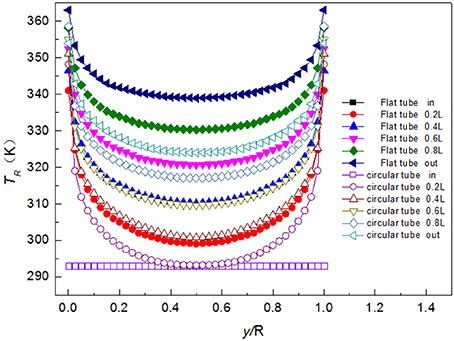
Figure 9. Comparison of the radial temperature along the section of two tubes.
Flow Characteristics Analysis
As shown in Figure 10, because the flow area of flat tube is relatively smaller compared with that of the circular tube, the medium velocity is higher and the pressure loss is larger. In addition, the viscosity of the nanofluid increases with concentration, which means the larger the concentration of the nanoparticles, the greater the flow resistance is. Therefore, the pressure drop of circular tube tubelines in each Reynolds number is lower than that of the corresponding flat tubes, and the pressure drop of each tubeline increases with the increase of Reynolds number. But the increase rate in the circular tube is lower than the flat tube. Compared with the circular tube, the pressure drop of water in flat tube increases by 55.25 ~ 66.91%, while the CuO-water nanofluids pressure drop increases by 72.76 ~ 79.09%.
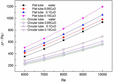
Figure 10. Comparison of pressure drop between flat tube and circular tube flow channel.
Due to the addition of nanoparticles in traditional fluids, their heat transfer capacity is enhanced, and the flow resistance is increased. Therefore, according to the literature (Qing and Zou, 2007), the comprehensive evaluation factor was introduced to analyze the heat transfer performance of the fluid. Its expression is as follows:
Where:Nu, f, d are the Nusselt number, the resistance coefficient and the equivalent diameter of the water and each concentration nanometer fluid in the flat tube respectively; Nu0, f0, d0 is the Nusselt number, the resistance coefficient and the equivalent diameter of the water and the concentration nanometer fluid in the circular tube respectively.
Where:h is the average heat transfer coefficient of the fluid; L is the length of the test section; k is the coefficient of thermal conductivity.
Where: ΔP is the pressure drop; di is the equivalent diameter of the heat tube; ρ is the fluid density; u is the average velocity.
As shown in Table 3, under the same Reynolds number, the comprehensive evaluation factors decreases with the increase of the concentration of nanoparticles in the fluids, but all >1. This shows that with the increase of nanofluids concentration, the comprehensive heat transfer ability of the flat tube relative to the circular tube decreases gradually, but in the range of this data, any working quality is always better than the circular tube. For the same concentration of fluid, the evaluation factor increases with the increase of Reynolds number, that is, the more general Reynolds number of nanofluids applied to the flat tube, the better the effect.
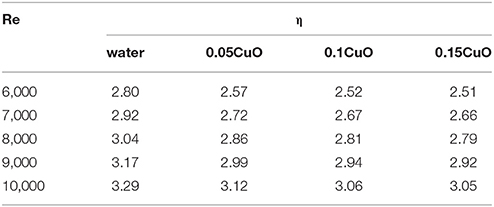
Table 3. Comprehensive evaluation factors of fluid in flat tube and circular tube at different Reynolds number and concentration.
Conclusion
In this paper, the numerical simulation method is used to compare the flow and heat transfer characteristics of the water and the nanofluids in the two heat transfer tubes, and the following conclusions are drawn:
(1) The greater the concentration of the nanoparticles in the fluid, the greater the average heat transfer coefficient, and the maximum is reached at 0.15. Compared with the circular tube, the nanofluid has a higher heat transfer coefficient when it flows in the flat tube, but it is better to improve the heat transfer coefficient when it is applied to the tube.
(2) The axial and radial temperature trends of each concentration of nanofluids are basically the same, and the concentration of nanoparticles in fluids has little effect on the temperature distribution. In conditions with the same Reynolds number and concentration, the average temperature along the axial cross-section of the flat tube is higher than the corresponding circular tube.
(3) With the same Reynolds number, the resistance of the flat tube runner is higher than that of the circular tube, and with the increase of concentration, the growth rate of the flow channel pressure drop of the two heat transfer tubes increases gradually, and the growth rate of the flat tube is always greater than that of the tube.
(4) Under the same Reynolds number, the comprehensive heat transfer capacity of the flat tube is better than that of the circular tube. However, with the increase of the concentration of nanofluids, the increase of the resistance caused by fluid viscosity is greater than that of the fluid heat transfer enhancement, resulting in the gradual decrease of the comprehensive evaluation factor.
(5) For the same fluid, the comprehensive evaluation factor of the flat tube relative to the circular tube increases with the increase of Reynolds number, that is, the larger the Reynolds number, the better the effect of applying the nanometer fluid to the flat tube.
Author Contributions
In the course of the completion of this thesis, all authors have substantial contributions to design of the work, GF provided the research direction of the subject, LS determined the research method and specific processes. LS carried out numerical simulation and obtained, collated and analyzed the data, in the process, GF has been instructed and helped. LS wrote the first draft of the paper and corrected it by GF also gave some suggestions. All authors approve the final version to be published. All authors agree to be responsible for all aspects of the work.
Conflict of Interest Statement
The authors declare that the research was conducted in the absence of any commercial or financial relationships that could be construed as a potential conflict of interest.
Acknowledgments
I would like to extend my sincere gratitude to my supervisor for his instructive advice and useful suggestions on my thesis. I am deeply grateful for her help in the completion of this thesis. This work is supported by Key Supported Discipline of Guizhou Provence (Qian Xuewei He Zi ZDXK [2016]24), 2011 Collaborative Innovation Center of Guizhou Province (Qian Jiao he xietongchuangxin zi [2016]02).
Nomenculture
Cp Specific heat at constant pressure, J·(kg·K)−1; d equivalent diameter of the heat tube, m; f resistance coefficient; h heat transfer coefficient, W·(m2·K)−1; L test section length, m; Nu Nusselt number; ΔPtubeline pressure drop, Pa; Re Reynolds number; u fluid velocity, m/s
Greek Symbols
ρ fluid density, kg/m3; β thermal expansion coefficient; K−1; μdynamic viscosity, Pa·s.
References
Banerjee, D. (2017). “Nanofluids and applications to energy systems,” in Reference Module in Earth Systems and Environmental Sciences, ed M. A. Abraham (Elsevier), 429–439
Chen, Y. J., Wang, P. Y., Liu, Z. H., and Li, Y. Y. (2013). Heat transfer characteristics of a new type of copper wire-bonded flat heat pipe using nanofluids. Int. J. Heat Mass Transf. 67, 548–559. doi: 10.1016/j.ijheatmasstransfer.2013.08.060
Choi, S. U. S. (1995). Enhancing thermal conductivity of fluids with nanoparticles. Am. Soc. Mech. Eng. Fluids Engin. Div. 231, 99–105.
Eastman, J. A., and Choi, U. S. (2001). Development of Energy-Difficient Nanofluids for Heat Transfer Applications. Report of Argonne National Laboratory.
Ganvir, R. B., Walke, P. V., and Kriplani, V. M. (2016). Heat transfer characteristics in nanofluid-A review. Renew. Sustain. Energy Rev. 75, 451–460. doi: 10.1016/j.rser.2016.11.010
Hwang, K. S., Jang, S. P., and Choi, S. U. S. (2009). Flow and convective heat transfer characteristics of water-based Al2O3 nanofluids in fully developed laminar flow regime. Int. J. Heat Mass Transf. 52, 193–199. doi: 10.1016/j.ijheatmasstransfer.2008.06.032
Ji, Z., Diao, Y., Zhao, Y., and Zhang, Y. (2014). Experimental study of TiO2-water nanofluid flow and heat transfer characteristics in a multiport minichannel flat tube. Int. J. Heat Mass Transf. 79, 628–638. doi: 10.1016/j.ijheatmasstransfer.2014.08.071
Khoshvaght-Aliabadi, M., Nouri, M., Sartipzadeh, O., and Salami, M. (2016). Performance of agitated serpentine heat exchanger using metallic nanofluids. Chem. Engin. Res. Design 109, 53–64. doi: 10.1016/j.cherd.2016.01.012
Kumar, V., Tiwari, A. K., and Ghosh, S. K. (2015). Application of nanofluids in plate heat exchanger: a review. Energy Conv. Manag. 105, 1017–1036. doi: 10.1016/j.enconman.2015.08.053
Li, Q., and Xuan, Y. (2002). Connective heat transfer and flow characteristics of cu-water nanofluid. Sci. China Ser. E. 45, 405–416. doi: 10.3969/j.issn.1674-7259.2002.03.006
Liu, D., and Yu, L. (2010). Single-phase thermal transport of nanofluids in a minichannel. J. Heat Transf. 133:031009. doi: 10.1115/1.4002462
Qiang, L. I., and Yi-Min, X. (2004). Flow and heat transfer performance of nanofluids inside small hydraulic diameter flat tube. J. Eng. Thermophys. 25, 305–307. doi: 10.3321/j.issn:0253-231X.2004.02.038
Qing, D. P., and Zou, J. Z. (2007). Evaluation and application of heat transfer enhancement for spiral flat tube condenser. Fluid Mach. 35, 79–81. doi: 10.3969/j.issn.1005-0329.2007.01.020
Rao, J., Chen, S., Qi, P., An, H., and Li, Y. (2003). Influence of pH values and dispersant mass fractions on dispersive property of nano-zirconia suspension. J. Qingdao Univers. 16, 37–39.
Solangi, K. H., Kazi, S. N., Luhur, M. R., Badarudin, A., Amiri, A., Sadri, R., et al. (2015). A comprehensive review of thermo-physical properties and convective heat transfer to nanofluids. Energy 89, 1065–1086. doi: 10.1016/j.energy.2015.06.105
Sun, C. J., Sun, B. M., and Zhong, Y. F. (2015). Numerical simulation of heat transfer enhancement in CuO-water nanofluids. Therm Power Engin. 30, 200–204. doi: 10.16146/j.cnki.rndlgc.2015.02.006
Wang, B. X., Li, C. H., and Peng, X. F (2003). Sta-bility of nano-particle suspensions. J. Basic Sci. Eng. 11, 167–173. doi: 10.16058/j.issn.1005-0930.2003.02.008
Wen, D., and Ding, Y. (2004). Experimental investigation into convective heat transfer of nanofluids at the entrance region under laminar flow conditions. Int. J. Heat Mass Transf. 47, 5181–5188. doi: 10.1016/j.ijheatmasstransfer.2004.07.012
Yuan-Xun, Q. I. (2005). Experimental study on heat transfer characteristics and flow resistance characteristics of flat tube shell-type heat exchangers. Huazhong Univers. Sci. Technol. doi: 10.7666/d.j004926
Keywords: nanofluids, flat tube, numerical simulation, flow characteristics, heat transfer enhancement
Citation: She L and Fan G (2018) Numerical Simulation of Flow and Heat Transfer Characteristics of CuO-Water Nanofluids in a Flat Tube. Front. Energy Res. 6:57. doi: 10.3389/fenrg.2018.00057
Received: 31 December 2017; Accepted: 05 June 2018;
Published: 21 June 2018.
Edited by:
Uwe Schröder, Technische Universitat Braunschweig, GermanyReviewed by:
Claudio Tenreiro, University of Talca, ChileKhalil Ur Rahman, Pakistan Nuclear Regulatory Authority (PNRA), Pakistan
Copyright © 2018 She and Fan. This is an open-access article distributed under the terms of the Creative Commons Attribution License (CC BY). The use, distribution or reproduction in other forums is permitted, provided the original author(s) and the copyright owner are credited and that the original publication in this journal is cited, in accordance with accepted academic practice. No use, distribution or reproduction is permitted which does not comply with these terms.
*Correspondence: Guangming Fan, fanguangming007@hotmail.com
Luchao She, sheluchaowy@163.com