Research on the Pump Shaft Stability Analysis of Multistage Centrifugal Pump During Closed-Valve Start-Up Process
 Yun Long
 Bin Lin
 Jie Fang
 Jie Ge2
  Qiang Fu
 Rongsheng Zhu
- 1China National Research Center of Pumps, Jiangsu University, Zhenjiang, China
- 2Shimge Pump Industry (Zhejiang) Co., Ltd., Wenling, China
In order to analyze the pump shaft stability of multistage centrifugal pump during the closed-valve start-up process, the transient internal fluid field and structural field during the closed-valve start-up process of the TDM 35-140 × 13 segmental multistage centrifugal pump are solved by transient fluid-solid coupling. The transient deformation and vibration velocity of the pump shaft are analyzed. It is found that the maximum deformation amount of the third stage impeller and the pump shaft cylindrical contact surface (N = 7 node area) during the whole closed-valve transition start-up process is the largest. The maximum deformation in the region where the nodes 1 ≤ N ≤ 10 are significantly greater than that in other regions. In the 11 ≤ N ≤ 19 node, with the node position coordinate value N increasing, the maximum deformation amount is continuously decreasing. During the entire closed-valve transition start-up process, the vibration speed of the pump shaft fluctuates drastically. In the node of 1 ≤ N ≤ 19, with the node position coordinate value N increasing, the maximum vibration velocity first increases and then decreases. The maximum vibration speed at N = 11 nodes is higher than that of all other nodes.
Introduction
During the frequent start-up process of multistage centrifugal pump, the structural part in contact with the internal fluid will be affected by the changing fluid pressure. Therefore, the rotor structure will generate stress response according to the change of pressure load with time (Chen, 2016; Fu, 2016; Liu et al., 2017), which can easily cause vibration damage and affect the safe operation of the pump. At present, the quasi-steady state assumption method is generally used to replace the transient process in the start-up process of centrifugal pump (Ping et al., 2007; Li, 2009; Li et al., 2010; Xu et al., 2010), but due to the obvious transient effect, its numerical simulation is inaccurate (Guo et al., 2019; Zhou et al., 2019). Therefore, the stability of pump shaft in the start-up process of multistage centrifugal pump is still lack of systematic research.
Katsutoshi et al. (2010) used fluid-solid coupling method to predict the stress of mixed-flow pump under different flow conditions. It was found that at 70% of the designed flow rate, the flow separation occurred at the leading edge of suction side on the blade surface, resulting in the greatest stress. Based on APDL parametric design language, Li et al. (2012) developed a program for calculating the strength of multistage centrifugal pump shaft, established the pump shaft model under zero flow and design point conditions, and made a clear and accurate description of the stress distribution, strength and dangerous point position of different cross-sections of the pump shaft. Li et al. (2017; 2018; 2019a; 2019b; 2019c) discussed its generating mechanism, accompanying unsteady phenomena and corresponding hysteresis phenomena. Investigations on the influence of geometric and operating unit parameters were presented. Finally, precautions and countermeasures for the improvement of positive slopes and various perspectives regarding future work were proposed. Wu et al. (2015) performed fluid-solid coupling numerical calculation on the structural stress field and internal flow field of a low specific speed centrifugal pump during the closed-valve start-up process. The differences of external characteristics, internal flow field distribution and pressure fluctuation before and after considering fluid-solid coupling effect were compared and analyzed. Yuan et al. (2016) calculated the transient blade dynamic stress characteristics of IS65-50-160 centrifugal pump during start-up process by two-way fluid-solid coupling method, analyzed the steady state, instantaneous stress and stress deformation under the coupling effect, and obtained the variation of the transient effect on blade stress and strain under start-up condition of centrifugal pump. Zhang et al. (2019b; 2019c) carried out the effects of modifying the blade pressure side (EPS profile) on unsteady pressure pulsations and flow structures in a low specific speed centrifugal pump by experimental and numerical methods. From relative velocity distribution, it was found that the uniformity of flow field at the blade outlet region would improve significantly by the EPS profile. Tan et al. (2019) investigated the clocking effect of impellers and the superposition between pump stages caused by clocking effect in a five-stage centrifugal pump. The difference is mostly in vibration frequency and amplitude, little in pump head and efficiency. Bai et al. (2019) established a vibration test bench to examine the vibration and stability of a cantilever multistage centrifugal pump under different flow rates. The results showed that the major type of vibration frequency for the inlet and outlet was high frequency. Xu et al. (2019) analyzed the fluid-induced forces of the clearance flow in canned motor RCP and their effects on the rotodynamic characteristics of the pump are numerically and experimentally analyzed. The results showed that clearance flow brought large mass coefficient into the rotodynamic system and the direct stiffness coefficient is negative under the normal operating condition.
Many scholars have studied the fluid-solid coupling of multistage centrifugal pumps mostly limited to the stable operation conditions, and the effect of fluid-solid coupling on the internal flow field during the start-up process of multistage centrifugal pumps is relatively small (Li et al., 2019d; Zhang et al., 2019a,d). The model TDM 35-140 × 13 multistage centrifugal pump is chosen as the research object. During the closed-valve start-up process, the radial force changes significantly with the increase of start-up time, and the pump shaft is prone to severe vibration, wear and even fracture. Therefore, it is necessary to make transient dynamic analysis of the pump shaft under the closed-valve transient start-up process. This paper studies the transient dynamics of the pump shaft based on the Transient Structural module in ANSYS Workbench.
Computing Model and Mesh Generation
In this paper, the main design parameters of the multistage centrifugal pump selected are as follows: flow rate Qd = 34.1 m3/h, head H = 1800 m, speed n = 2985 r/min, ns = 26.3. The main geometric parameters of the flow passage parts of the model pump are shown in the Table 1.
Table 1. Dimensional parameters of impeller and radial guide vane.
Commercial software Cero is used to build the three-dimensional model of the flow passage area of the multistage centrifugal pump, including the suction chamber, impellers at all levels, radial guide vanes and extruder chambers. Compared with the other guide vanes at all levels, there is no anti-guide vane in the final guide vanes and the outlet of the last guide vanes directly contacts with the fluid field of the extruder chamber. The fluid field model of the multistage centrifugal pump is shown in Figure 1. The mesh independence is shown in Figure 2A. Considering that the internal fluid flow state varies greatly during the start-up process, the impeller is divided into structured mesh, which is shown in Figure 2B. Radial guide vane, suction chamber and pump casing adopt unstructured mesh with strong self-adaptability to realize complex structure mesh generation, which guarantees mesh quality above 3.0. Finally, the mesh number of suction chamber, pump casing and impeller are 570325, 107906, and 326751, respectively. The total mesh number of radial guide vane except the last stage is 144854 and 13763729.
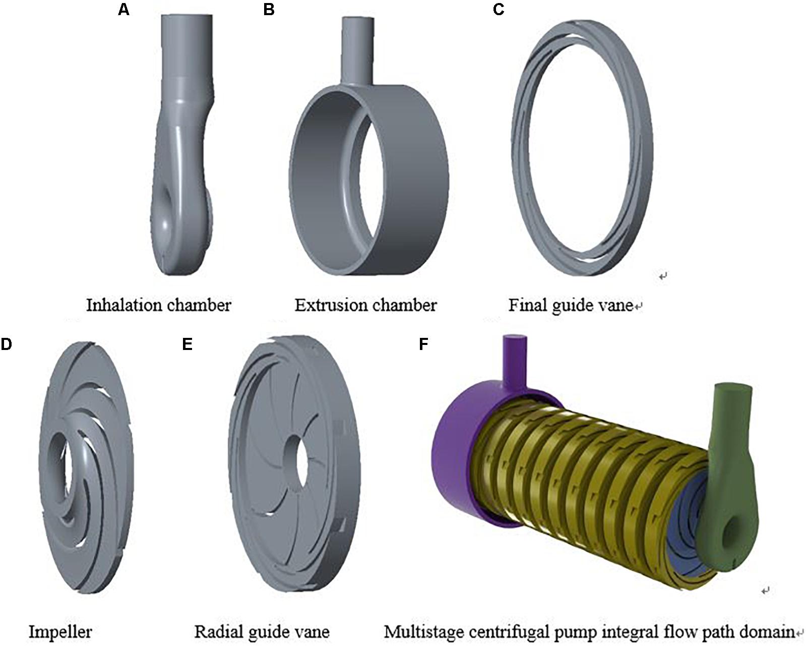
Figure 1. Fluid domain model of multistage centrifugal pump. (A) Inhalation chamber, (B) Extrusion chamber, (C) Final guide vane, (D) Impeller, (E) Radial guide vane, (F) Multistage centrifugal pump integral flow path domain.
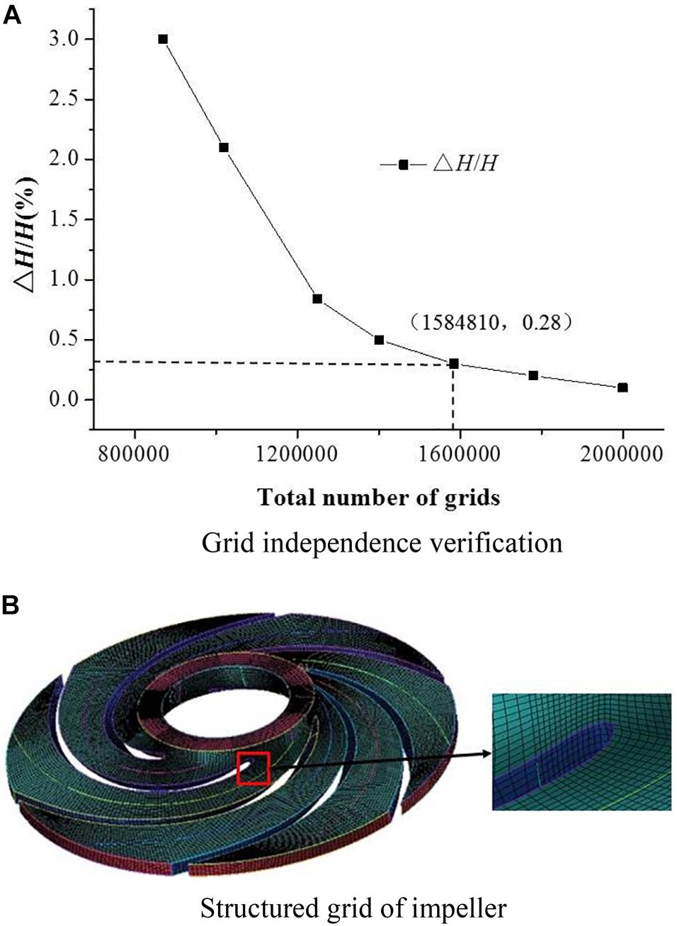
Figure 2. Meshing. (A) Grid independence verification, (B) Structured grid of impeller.
Turbulence Model and Boundary Condition Setting
This paper based on ANSYS CFX 18.1 to complete the start-up transient simulation numerical calculation. The Shear Stress Transport (SST) model is used in the turbulence model. The results of steady flow field with zero rotational speed and flow rate are taken as initial documents. The interface between impeller and radial guide vane is set as Frozen rotor mode with fixed rotor, the wall roughness is set as 0.125 mm, and the wall boundary condition is set as non-slip wall. The import boundary condition is set as the full pressure inlet, and the reference pressure is set as 1 atm. The outlet boundary condition is set as the mass flow outlet. The turbulence intensity is set as Medium Intensity = 5%. When the closed-valve start-up starts at the shut off condition, the flow rate can be regarded as 0. But in fact, the internal flow of multistage centrifugal pump is still circulating under small flow rate, and the flow rate can be regarded as a constant value during the whole shut-off start-up process (Shao, 2016). The flow rate is about 1∼5% of the design flow rate of the pump, and the mass flow rate is 0.01 kg/s. The total calculation time of close-valve transition stage is set to 2.5 s, and the time step is 0.002 s. In order to ensure absolute convergence within each time step, the maximum number of iterations within a time step is set to 50, and the residual value of convergence is set to 0.0001.
The relationship of the speed change during the closed-valve start-up process is loaded onto the impeller by writing an expression function expression. The rated speed is 2985 r/min and the total calculating time is 2.5 s. The law of speed change is shown in Figure 3.
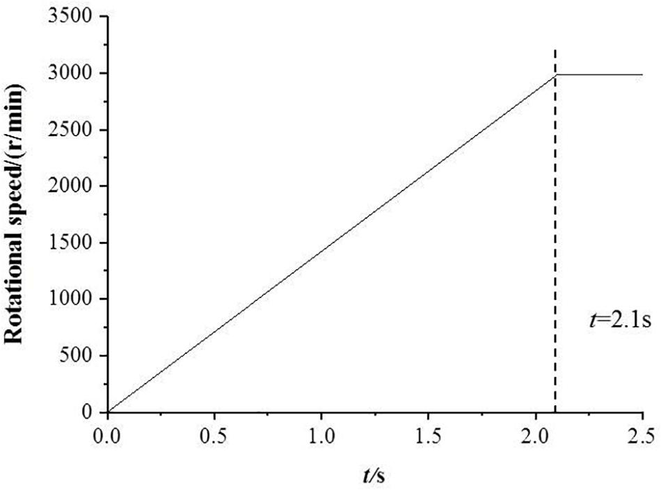
Figure 3. Rotating speed change diagram of impeller.
The equation for calculating speed in expression function of close-valve transition stage is shown in Eq. 1.
The rotational speed nt remains constant during the open-valve transition stag, i.e., nt = −2985 r/min.
In Eq. 1, Ttol = 2.1 s, which means the start-up time is 2.1 s, among them function step (x) is the function of CFX itself, and its expression value is shown in Eq. 2.
In Eq. 2, x is dimensionless.
Instantaneous Dynamic Analysis Setting of Pump Shaft
The x-direction radial force Fx and the y-direction radial force Fy of the impellers of different stages monitored in the closed-valve start-up transient calculation are applied to the cylindrical contact surface of the impeller and the pump shaft. At the same time, the gravitational acceleration and the rotational speed as a function of time are added to the entire pump shaft. The Mesh module in ANSYS Workbench is used to unstructured the structural part of the pump shaft solid domain. Considering the accuracy of calculation and calculation time, the pump shaft mesh size is set to 8 mm, the total mesh node number is 130876. The pump shaft mesh and monitoring node distribution are shown in Figure 4. The direction indicated by the arrow is the position of the monitoring point. The 5th to 17th nodes are the monitoring nodes on the cylindrical surface in contact with the impeller and the pump shaft. A fixed constraint is applied on the thrust bearing surface, and a cylindrical constraint is applied on the radial bearing surface. The constraint direction of the bearing surface on the inlet side of the impeller is set to radial tangential constraint, and the axial direction is free, while the constraint direction of the bearing surface on the outlet side is set as radial axial constraint, and the tangential is free. The transient dynamics analysis of the pump shaft is shown in Figure 5. Due to the excessive number of monitoring nodes, when the analysis determines the maximum deformation amount and vibration velocity over time during the whole closed-valve start-up process, only five nodes at the typical N = 3, 7, 11, 15, 19 are selected. The material of the pump shaft is ZG06Cr13NI4Mo, and the material properties of the material are shown in Table 2.
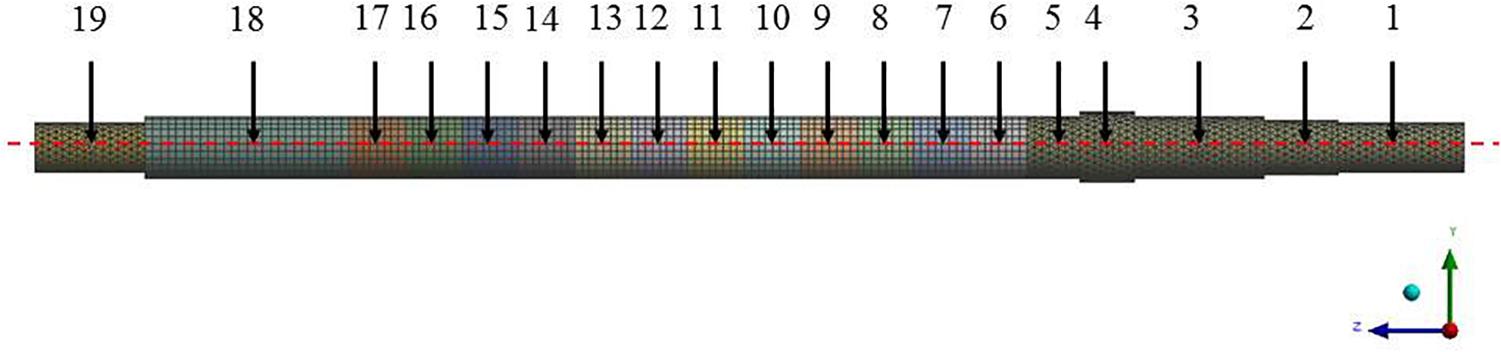
Figure 4. Pump shaft mesh and monitoring node distribution.
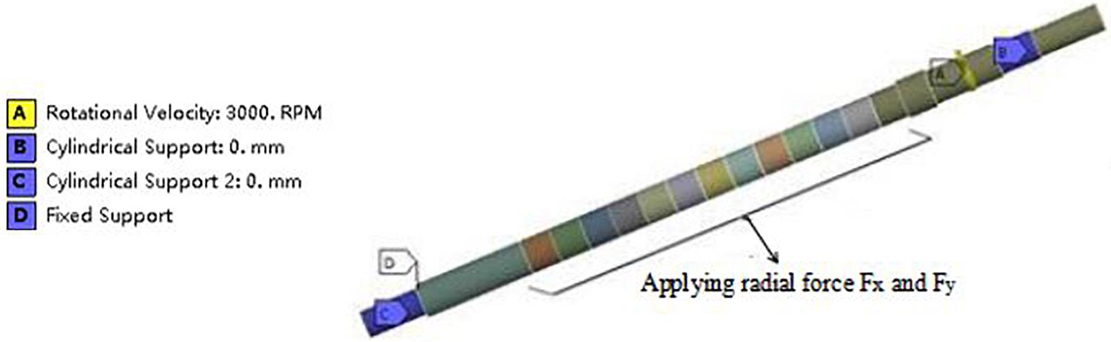
Figure 5. Setting diagram for transient dynamics analysis of pump shaft.
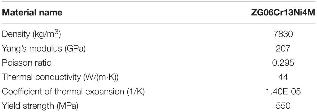
Table 2. Material physical property coefficient.
Radial Force Analysis of Impeller During the Closed-Valve Start-Up Process
During the centrifugal pump of the closed-valve start-up process, the radial force of the impeller is in a state of sharp change due to fluid acceleration and rotation. The evolution law of the force during the closed-valve transient start-up process is completely different from the variation of the constant speed condition. However, there is no calculation equation for the radial force of the impeller under the pump starting condition. Therefore, only numerical simulation can be used to predict the evolution of the radial force of the impeller. Due to the excessive number of stages, only the typical 1st, 2nd, 3rd, 7th, and 13th levels are selected for analysis. The radial force in this section is the resultant force in the x and y directions. The radial force changes of the 1st, 2nd, 3rd, 7th, and 13th stages of the closed-valve start-up process are shown in Figure 6.
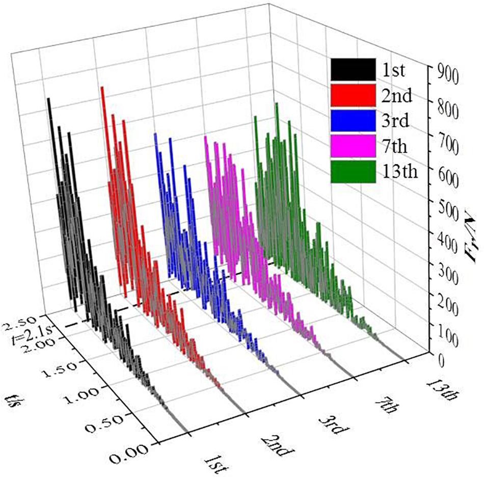
Figure 6. Radial force change diagram of impellers with different series during the closed-valve start-up.
It can be seen from Figure 6 that the impeller radial force of different stages fluctuates greatly with time during the closed-valve transition start-up process. In the initial stage of the closed-valve 0 s ≤ t ≤ 0.5 s, the multistage centrifugal pump has just started, and the impeller radial force is close to zero. As the start-up process develops, the impeller radial force increases gradually. At the end of the start-up process 2.1 s ≤ t ≤ 2.5 s, the impeller oscillations of different stages are within a certain range, and the average radial force of the first and second stages is greater than the third, seventh, and third stages.
The transient dynamics calculation results of the pump shaft during the closed-valve transient start-up process include the maximum deformation and vibration speed of the pump shaft. These two parameters can directly reflect the vibration deformation of the pump shaft during the closed-valve start-up process. The vibration speed of the pump shaft represents the derivative value of the maximum deformation amount of the pump shaft with respect to time.
Analysis of Maximum Deformation of Pump Shaft
The change of the maximum deformation amount at different monitoring nodes during the closed-valve start-up process with time is shown in Figure 7. It can be seen from the Figure 7 that the variation trend of the maximum deformation of different monitoring points with time is similar. In the initial stage of the closed-valve start-up process 0 s ≤ t ≤ 0.25 s, the maximum deformation of the pump shaft is close to zero, and the value remains almost unchanged. Within 0.25 s ≤ t ≤ 2.1 s, the maximum deformation of the pump shaft begins to increase slowly until it approaches a linear increase. The maximum deformation of the pump shaft remains periodically fluctuating within 2.1 s ≤ t ≤ 2.5 s at the end of the closed-valve start-up process. The most typical deformation at the 3rd, 7th, 10th, 12th, 14th, 16th, 17th, and 19th nodes are selected, where the maximum deformation of the nodes at N = 7 is higher than all other nodes. The seventh node is the monitoring node on the contact surface between the third stage impeller and the pump shaft cylinder. At t = 2.2 s, the maximum deformation of the pump shaft reaches the maximum deformation = 0.402 mm. Figure 8 is a distribution diagram of the deformation amount of the pump shaft at t = 2.2 s. The 3rd, 7th, and 10th deformation are relatively close during the closed-valve start-up process. With the number of nodes increasing, the maximum deformation at the 12th, 14th, 16th, 17th, and 19th nodes gradually decrease.
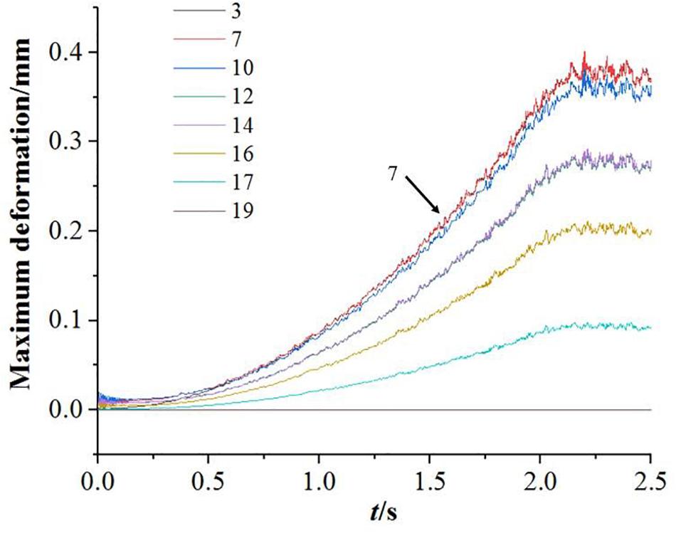
Figure 7. The maximum deformation varies with time.
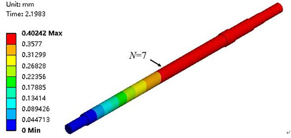
Figure 8. Distribution of deformation of pump shaft t = 2.2 s.
Figure 9 shows the maximum deformation amount of 0 s ≤ t ≤ 2.1 s during the entire closed-valve start-up process of the different monitoring nodes. It can be seen from Figure 9 that the maximum deformation amount at the nodes of the 1 ≤ N ≤ 9 is almost equal, and the maximum deformation amount at the node of N = 7 is slightly higher than that of the other nodes. The ninth node is the monitoring node on the contact surface between the fifth stage impeller and the pump shaft cylinder. The maximum deformation amount of the area 1 ≤ N ≤ 10 is larger than other areas. In the 11 ≤ N ≤ 19 node, with the node position coordinate value N increasing, the maximum deformation amount is continuously decreasing.
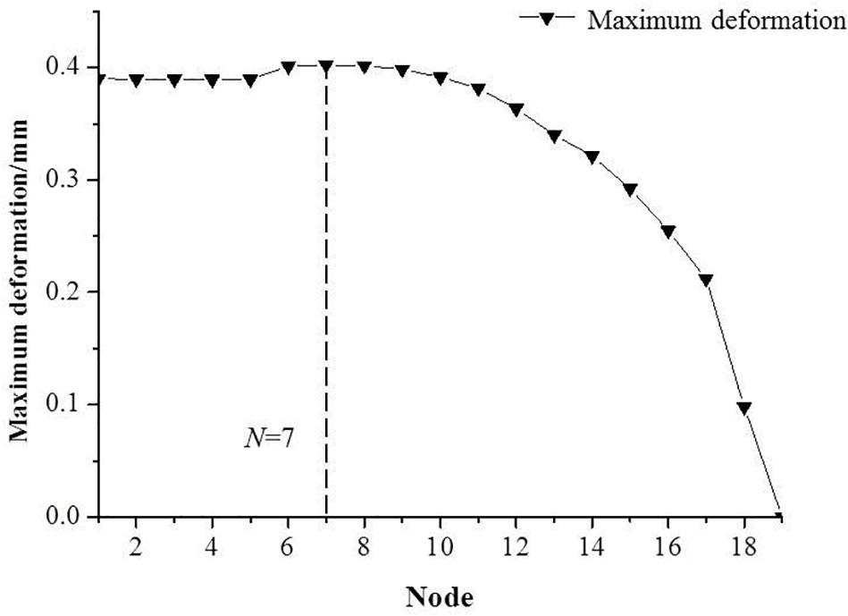
Figure 9. Maximum deformation at different monitoring nodes.
Vibration Speed Analysis of Pump Shaft
Figure 10 shows the change of vibration velocity at different monitoring nodes with time during the closed-valve start-up process. The vibration speed of the pump shaft fluctuates drastically during the entire closed-valve start-up process. When the initial stage of the closed-valve transition start-up process at 0 s ≤ t ≤ 0.15 s, the vibration speed of the pump shaft slowly drops to zero. It remains unchanged within 0.15 s ≤ t ≤ 0.6 s, increases continuously within 0.6 s ≤ t ≤ 2.0 s, decreases first and then increases within 2.0 s ≤ t ≤ 2.2 s, and decreases continuously within 2.2 s ≤ t ≤ 2.5 s after closed-valve start-up process. At t = 2.2 s, the maximum deformation and vibration speed of the pump shaft simultaneously reach the maximum vibration velocity = 90.40 mm/s. Figure 11 shows the vibration velocity distribution of the pump shaft at t = 2.2 s. The vibration velocity of the node at N = 11 is higher than the maximum deformation amount in all nodes. The eleventh node is the monitoring node on the contact surface of the seventh stage impeller and the pump shaft cylinder.
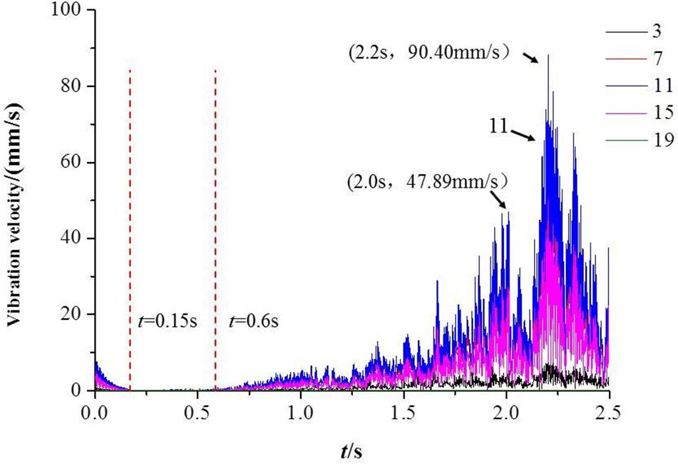
Figure 10. Vibration velocity change diagram with time.
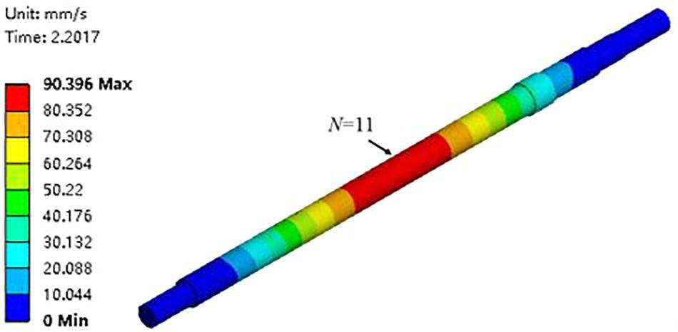
Figure 11. Distribution of vibration velocity of pump shaft at t = 2.2 s.
Figure 12 shows the maximum vibration velocity of the different monitoring nodes in the whole closed-valve start-up process 0 s ≤ t ≤ 2.1 s. In the nodes of 1 ≤ N ≤ 19, with the node position coordinate value N increases, the maximum vibration velocity first increases and then decreases. The maximum vibration speed at N = 11 node is higher than all other nodes.
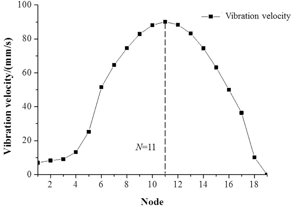
Figure 12. The maximum vibration velocity of different monitoring nodes.
Discussion
The transient internal fluid field and the structure field of the multistage centrifugal pump are solved by transient fluid-solid coupling and the transient deformation and vibration velocity of the pump shaft are analyzed. The maximum deformation of the contact surface between the third stage impeller and the cylinder of the pump shaft (N = 7 node area) is the largest during the whole closed-valve transition start-up process, and the maximum deformation of the area where 1 ≤ N ≤ 10 nodes is obviously larger than that of other areas. In 11 ≤ N ≤ 19 nodes, the maximum deformation decreases with the increases of the coordinate value N of the node position. At the initial stage of the closed-valve transition start-up process, the radial force and axial force of the impeller are close to zero, and the maximum deformation of the pump shaft increases slowly. With the development of the start-up process, the radial and axial force of the impeller gradually increases, and the radial force changes dramatically with time, but the overall radial force at different stages are not different. At the same time, the pump shaft vibration velocity fluctuation is also very violent. The maximum deformation and vibration velocity of the pump shaft reach the maximum when the rotation speed reaches the stability in the closed-valve start-up process.
Conclusion
Through the analysis of the stability of the pump shaft during the closed-valve start-up process of the multistage centrifugal pump, the following conclusions are drawn:
(1) At the initial stage of the closed-valve transition start-up process, the radial and axial forces of impeller are close to zero. With the development of start-up process, the radial and axial forces of impeller gradually increase, and the radial forces fluctuate sharply with time, but the overall radial forces of different stages are not different. The maximum deformation of pump shaft increases slowly. With the development of start-up process, the maximum deformation begins to increases gradually until it tends to increases linearly.
(2) When t = 2.2 s (the rotational speed stops increasing at t = 2.2 s), the maximum deformation and vibration speed of the pump shaft reach the maximum at the same time. The maximum deformation of the pump shaft is 0.402 mm, and the maximum vibration speed of the pump shaft is 90.396 mm/s.
(3) Vibration speed of pump shaft fluctuates sharply during the whole closed-valve transition start-up process. In the nodes of 1 ≤ N ≤ 19, with the node position coordinate value N increasing, the maximum vibration velocity first increases and then decreases. The maximum vibration speed at N = 11 nodes is higher than all other nodes.
(4) The study on the pump shaft stability analysis of multistage centrifugal pump during closed-valve start-up process not only guarantees the safe operation of the whole unit, but also improves the overall performance of the pump.
Data Availability Statement
The raw data supporting the conclusions of this article will be made available by the authors, without undue reservation.
Author Contributions
All authors listed have made a substantial, direct and intellectual contribution to the work, and approved it for publication.
Funding
This work was funded by the China Postdoctoral Science Foundation Funded Project (Grant No. 2019M651734), National Youth Natural Science Foundation of China (Grant No. 51906085), and Jiangsu Province Innovation and Entrepreneurship Doctor Project (2019). This work was also supported by Key R&D Programs of Jiangsu Province of China (BE2018112), and National Key R&D Program of China (2018YFB0606105). This work was also supported by Zhejiang Postdoctor Project (2019), and the project leader is Dr. Long Yun who carried out the research work at the Postdoctoral Workstation at Shimge Pump Industry Group CO., LTD.
Conflict of Interest
JG and LX were employed by the company Shimge Pump Industry (Zhejiang) CO., LTD. LY is a postdoc of the Postdoctoral Workstation at Shimge Pump Industry Group CO., LTD from 2019–2021.
The remaining authors declare that the research was conducted in the absence of any commercial or financial relationships that could be construed as a potential conflict of interest.
References
Bai, L., Zhou, L., Jiang, X., Pang, Q., and Ye, D. (2019). Vibration in a multistage centrifugal pump under varied conditions. Shock Vibrat. 2019:9.
Fu, J. (2016). Modal analysis of rotor of high-lift multistage centrifugal pump based on ANSYS Workbench. Jiangxi Water Resour. Sci. Technol. 42, 244–248.
Guo, G., Zhang, R., Zhao, Y., Yang, J., and Huang, Q. (2019). Numerical simulation of transient characteristics of snorkeling fire pump during startup process. J. Drain. Irrigat. Machin. Eng. 37, 112–117.
Katsutoshi, K., Shigeyoshi, O., Ichiro, H., and Yoshimasa, C. (2010). Numerical analysis of stress on pump blade by one-way coupled fluid-structure simulation. J. Fluid Sci. Technol. 5, 219–234. doi: 10.1299/jfst.5.219
Li, D., Fu, X., Zuo, Z., Wang, H., Li, Z., Liu, S., et al. (2019a). Investigation methods for analysis of transient phenomena concerning design and operation of hydraulic-machine systems—A review. Renew. Sustain. Energy Rev. 101, 26–46. doi: 10.1016/j.rser.2018.10.023
Li, D., Qin, Y., Zuo, Z., Wang, H., Liu, S., and Wei, X. (2019b). Numerical simulation on pump transient characteristic in a model pump turbine. J. Fluids Eng. Trans. ASME 141:111101.
Li, D., Zuo, Z., Wang, H., Liu, S., Wei, X., and Qin, D. (2019c). Review of positive slopes on pump performance characteristics of pump-turbines. Renew. Sustain. Energy Rev. 112, 901–916. doi: 10.1016/j.rser.2019.06.036
Li, T., Wang, Y., Kang, Y., Zhao, C., and Song, X. (2019d). Numerical simulation of fluid - solid rotating motion of rigid elliptic cylinder. J. Drain. Irrigat. Machin. Eng. 37, 112–117.
Li, D., Wan, H., Qin, Y., Li, Z., Wei, X., and Qin, D. (2018). Mechanism of high amplitude low frequency fluctuations in a pump-turbine in pump mode. Renew. Energy 126, 668–680. doi: 10.1016/j.renene.2018.03.080
Li, D., Wang, H., Qin, Y., Han, L., Wei, X., and Qin, D. (2017). Entropy production analysis of hysteresis characteristic in the hump region of a pump-turbine model. Energy Conver. Manag. 149, 175–191. doi: 10.1016/j.enconman.2017.07.024
Li, W., Shi, W., Shen, Y., Jiang, X., and Pang, Z. (2012). Finite element analysis of shaft strength of multistage centrifugal pump based on APDL. J. Agric. Machin. 43, 69–73.
Li, Z. (2009). Numerical Simulation and Experimental Research on the Transient Flow in the Start-Up Process of Centrifugal Pump. Zhejiang: Zhejiang University.
Li, Z., Wu, D., Wang, L., Dai, W., and Chen, F. (2010). Test of transient characteristics of centrifugal pump starting process. J. Drain. Irrig. Machin. Eng. 28, 389–393.
Liu, Z. X. C. L. Y. W. K. (2017). Rotor modal analysis of multi-stage guide vane centrifugal pump based on fluid-solid coupling. Hydropower Energy Sci. 35, 151–154.
Ping, S., Wu, D., and Wang, L. (2007). Transient effect analysis of rapid opening process of centrifugal pump. J. Zhejiang Univ. 41, 814–817.
Shao, C. (2016). Research on Transient Process Characteristics of Ultra-Low Specific Speed Centrifugal Pump. Zhenjiang: Jiangsu University.
Tan, M., Lian, Y., Wu, X., and Liu, H. (2019). Numerical investigation of clocking effect of impellers on a multistage pump. Eng. Comput. 36, 1469–1482.
Wu, X., Tan, G., Liu, H., and Ding, J. (2015). The effect of fluid-solid coupling on the flow at the closing point of centrifugal pump. J. Appl. Found. Eng. Sci. 23, 172–181.
Xu, B., Li, Z., Wu, D., and Wang, L. (2010). Numerical simulation of transient turbulent flow during centrifugal pump start-up. Chinese Sci. Technol. Paper 5, 683–687.
Xu, R., Long, Y., Hu, Y., Yin, J., and Wang, D. (2019). Numerical and experimental research on the fluid-induced forces of clearance flow in canned motor reactor coolant pump. Energy Weekly News 2017:18.
Yuan, J., Xia, S., Zong, W., Zhou, B., and Fu, Y. (2016). Transient blade dynamic stress characteristics during centrifugal pump start-up based on fluid-solid coupling. Vibrat. Impact 35, 197–202.
Zhang, H., Chen, B., Wang, Y., Xu, Y., and Wang, Z. (2019a). Influence of mass imbalance on radial force of single-blade impeller. J. Drain. Irrigat. Machin. Eng. 37, 112–117.
Zhang, N., Liu, X., Gao, B., Wang, X., and Xia, B. (2019b). Effects of modifying the blade trailing edge profile on unsteady pressure pulsations and flow structures in a centrifugal pump. Int. J. Heat Fluid Flow 75, 227–238. doi: 10.1016/j.ijheatfluidflow.2019.01.009
Zhang, N., Liu, X., Gao, B., and Xia, B. (2019c). DDES analysis of the unsteady wake flow and its evolution of a centrifugal pump. Renew. Energy 141, 570–582. doi: 10.1016/j.renene.2019.04.023
Zhang, Z., Shi, W., Zhang, D., Chen, Z., and Huang, J. (2019d). Modal analysis of rotor parts of LNG low temperature submersible pump based on thermo-fluid-structure coupling. J. Drain. Irrigat. Machin. Eng. 37, 112–117.
Keywords: multistage centrifugal pump, closed-valve start-up process, pump shaft stability, numerical simulation, transient characteristics
Citation: Long Y, Lin B, Fang J, Ge J, Xu L, Fu Q and Zhu R (2020) Research on the Pump Shaft Stability Analysis of Multistage Centrifugal Pump During Closed-Valve Start-Up Process. Front. Energy Res. 8:186. doi: 10.3389/fenrg.2020.00186
Received: 30 April 2020; Accepted: 14 July 2020;
Published: 23 September 2020.
Edited by:
Zhanjie Xu, Karlsruhe Institute of Technology (KIT), GermanyReviewed by:
Luteng Zhang, Chongqing University, ChinaKeyou S. Mao, Oak Ridge National Laboratory (DOE), United States
Copyright © 2020 Long, Lin, Fang, Ge, Xu, Fu and Zhu. This is an open-access article distributed under the terms of the Creative Commons Attribution License (CC BY). The use, distribution or reproduction in other forums is permitted, provided the original author(s) and the copyright owner(s) are credited and that the original publication in this journal is cited, in accordance with accepted academic practice. No use, distribution or reproduction is permitted which does not comply with these terms.
*Correspondence: Yun Long, longyun@ujs.edu.cn; Qiang Fu, ujsfq@sina.com