Degradation of MCFC Materials in a 81 cm2 Single Cell Operated Under Alternated Fuel Cell/Electrolysis Mode
 Stefano Frangini1*
  Massimilano Della Pietra1
  Livia Della Seta1
  Claudia Paoletti1 Juan Pedro Pérez-Trujillo2
- 1TERIN-PSU-ABI, Italian National Agency for New Technologies, Energy and Sustainable Economic Development (ENEA), CR Casaccia, Rome, Italy
- 2Department of Mechanical Engineering, DICIS, University of Guanajuato, Guanajuato, Mexico
The possibility of producing hydrogen from molten carbonate steam electrolysis using the well-established Molten Carbonate Fuel Cell (MCFC) technology was explored in this work. For this purpose, a 81 cm2 MCFC single cell assembled with conventional cell materials was operated under alternated fuel cell/electrolysis conditions at 650°C in a binary eutectic Li2CO3-K2CO3 electrolyte for about 400 h after an initial period of 650 h in which the cell worked only in the usual MCFC mode. A rapid cell performance loss in terms of cell internal resistance and electrode polarization was observed as soon as the cell started to work in the alternated fuel cell/electrolysis mode. After test completion, a post-mortem analysis was conducted to correlate the electrochemical response with cell materials degradation. Cell materials of the reverse cell were compared against a reference single cell that was assembled with the same materials and operated only in the fuel cell mode under comparable experimental conditions. Post-mortem analysis allowed to identify several serious stability issues of conventional MCFC materials when used in alternated operation modes. Thus, although the electrolyte matrix appeared almost unaffected, a significant amount of dissolved nickel was found in the matrix indicating that electrolysis operations promote an increasing chemical instability of the NiO oxygen electrode. A serious reduction of electrode porosity was also observed in both NiO oxygen and Ni metal fuel electrodes, which could explain the higher polarization resistance of the reversible cell in comparison to the reference MCFC cell. Furthermore, the oxygen current collector made with conventional 316L stainless steel was found to be seriously corroded under the alternated operation modes. Thus, the observed rapid increase in internal resistance in the reverse cell could be caused, at least in part, by an increased contact resistance between the oxygen electrode and the corroding current collector structure. Possible solutions for improving stability of electrodes and of the oxygen current collector in reverse MCFC cells were proposed and discussed in the final part of the work.
Introduction
There is wide consensus among the major scientific organizations that a rapid reduction of fossil fuel production is urgent to avoid catastrophic climate changes by the end of this century. For instance, according to a recent UN forecast, a cut of greenhouse gas emissions by 7.6% each year in the decade between 2020 and 2030 is required to achieve the Paris Agreement target and thus limiting the average temperature rise to an acceptable 1.5°C (United Nations Environment Programme [UNEP], 2019). Thus, as a part of global efforts toward the transition to a climate neutral economy re-shaped on renewable and decarbonized energy sources, the use of electrochemical technologies is recently gaining tremendous importance in the power sector as the most promising approach for fossil-free production of fuels such as hydrogen, methane and syngas (Godula-Jopek, 2015; Thema et al., 2019).
Among others, electrochemical production of hydrogen by intermittent renewable energy sources is a recently emerging trend of research due to its impact in the electric/gas grid coupling sector (the so-called Power-to-Gas technology) (Götz et al., 2016). Water electrolysis by either reverse fuel cells or by reversible (unitized) fuel cells has been identified as the best option in Power-to-Gas technology for long-term storage and transport of renewable electricity in form of hydrogen to be used either as energy vector or as chemical feedstock, for instance, in Fischer-Tropsch or Sabatier methanation processes (Wang et al., 2016).
Since reverse fuel cell and reversible fuel cell are two distinct concepts that sometimes are confused with each other or used improperly, it seems useful to say that a reverse fuel cell simply indicates a fuel cell run in electrolysis mode, whereas a reversible fuel cell (RFC) is definable as the concept of integrating a fuel cell with an electrolyzer realizing thus a device that can work efficiently and reversibly in fuel cell mode for electricity production and in electrolysis mode for hydrogen production (Nguyen and Blum, 2016). RFCs are ideal to produce hydrogen from the surplus renewable electricity and converting it back into electricity on a needed basis through the use of the same conversion unit, offering thus a viable option for reducing the capital costs of storage and conversion electrochemical technologies of Power-to-Gas systems. Several studies demonstrate that in general fuel cell technologies can be adapted to work efficiently in both fuel cell and electrolysis mode with the most interesting results obtained with Polymer Electrolyte Membrane Fuel Cell (PEMFC) (Wang et al., 2016), Alkaline Fuel Cell (AFC) (Wang et al., 2017), Microfluidic Fuel Cell (MFC) (Wang et al., 2017) and Solid Oxide Fuel Cell (SOFC) (Wang et al., 2017; Mogensen, 2020) systems. Simple as it may seem, transformation of a conventional fuel cell into a reliable RFC system is however not a trivial challenge mainly due to accelerated degradation of the functional cell materials under dynamic operating conditions and difficulties in finding efficient bifunctional catalyst electrodes (Chen et al., 2018). In short, stable cycling operations and stable bi-functional electrode performance are two key requirements needed for adapting a fuel cell to work efficiently in a reversible fuel cell/electrolysis operation mode (Mogensen, 2020). For this reason, at present only reversible PEMFCs have reached an early stage of technology development, although applications are so far limited to aerospace and military sectors, being cost, and round-trip efficiency still major obstacles for large-scale energy-storage applications (Wang et al., 2016).
Compared with any other type of fuel cell, Molten Carbonate Fuel Cells (MCFCs) running in reverse mode have captured only a limited amount of research over the past few years, probably due to the fact that under the typical MCFC gas and temperature (ca. 650°C) conditions hydrogen with appreciable amounts of CO instead of pure hydrogen is being produced during steam electrolysis (Hu et al., 2015a). Interestingly, some recent studies indicate the possibility of producing pure hydrogen by operating a reverse MCFC yet in a mode different from electrolysis (Zhao et al., 2016; McVay et al., 2017). In these studies, a reverse MCFC has been used as an electrochemical CO2 selective membrane to pumping CO2 from a methane reformed gas stream and thus obtain high purity hydrogen (98–99% purity). Results indicate that the use of a reverse MCFC for H2/CO2 separation purposes is advantageous since electricity consumption to electrochemically separate CO2 and thus obtain a “CO2-free” hydrogen is as low as 70% of the power required if all hydrogen were produced directly by a steam electrolysis process.
An excellent description of state-of-the-art materials and components used in the conventional MCFC technology along with their main degradation issues can be found in Kulkarni and Giddey (2012). The oxygen electrode is traditionally a porous lithiated nickel oxide structure, which is produced by in situ oxidation and lithiation of a metallic nickel sinter during initial start-up. The fuel electrode is similarly a porous nickel metallic structure to which some Cr or Al is commonly added as sintering inhibitor. The two electrodes are separated by a thin layer of molten carbonate electrolyte confined in a porous inert alumina ceramic matrix. Austenitic stainless steels like 316L and 310S are used as current collectors. A thin Ni coating layer is usually applied at the fuel side of the steel current collectors for improved corrosion resistance.
The half-reactions taking place at the two electrodes in a molten carbonate electrolysis process are the opposite of the well-known MCFC reactions and can be schematically described as follows:
Performance and durability of reverse MCFC cells used for the steam electrolysis function have been evaluated so far by Hu et al. in a recent series of publications (Hu et al., 2014, 2015a,b, 2016a,b). Lab scale experiments were conducted by these authors using coin-type cells of small geometrical area (3 cm2) assembled with the conventional MCFC materials.
Their results indicate that in the temperature range 600–675°C the overall MCFC performance in electrolysis mode is slightly better than in fuel cell operation mode (Hu et al., 2014), which could open on the possibility of using conventional MCFC electrodes as efficient bi-functional electrode catalysts. Lower polarization losses of the porous NiO oxygen electrode were identified as the main cause for the better performance in electrolysis mode (Hu et al., 2014, 2015b). In particular, it was found that gas production at the NiO oxygen electrode [reaction (2)] takes place under a dominant charge transfer control (Hu et al., 2015b), being the role of mass transfer polarization negligible even at higher current densities, which is a striking difference as compared to a MCFC running in the conventional fuel cell mode. Although the possible causes for this behavior were not mentioned by the authors, it can be argued that the almost absence of mass transfer effects would be related to the high concentration of the carbonate, which is the reactant in the anodic electrolysis reaction. The carbonate concentration can be estimated to be in the order of 2 × 10⁻² mol per cm3 of electrolyte (see also Licht and Wu, 2011). On the contrary, the fuel cell reaction [inverse of reaction (2)] involves the electrochemical reduction of the sparingly soluble gaseous CO2 and O2 reactants, which are present in the melt only at ppm concentrations or even less. Thus, it is plausible to suppose that the irrelevant mass transfer effects observed in the electrolysis reaction are caused by a such higher carbonate concentration, which is at least 104 times higher than the concentration of the gaseous reactants in the fuel cell mode.
Long-term durability of a reversed MCFC was examined by the authors in a subsequent work using the same coin-type cells (Hu et al., 2016b). The electrolysis effect was evaluated at 650°C under both continuous and alternating operation modes. Some slight performance degradation of cell and electrodes was observed during continuous electrolysis for 2,165 h, whereas alternating electrolysis/fuel cell conditions resulted in an overall positive impact on the MCFC cell performance after 1,019 h operation, mainly due to a good stability performance of the NiO electrode. However, a detailed material degradation analysis of the cell components was not conducted in this study. The authors simply reported that post-test microstructural examination of the Ni and NiO electrodes did not allow to reveal any obvious change in comparison to the case of only fuel cell operations.
However, it should be noted that due to their small size coin-type cells operate with a minimal degree of conversion of reactant gases. Consequently, fuel cell reactions take place under largely isothermal and uniform current conditions, namely under conditions that are significantly far from real-life MCFC systems, where large-scale cells with over 1 m2 are used and where the high reactant conversion leads to significant gas composition and temperature gradients because of a long gas flow path along the cell. A wide consensus exists that such factors may lead to non-uniform current distribution and accelerated degradation of the cell materials (Selman and Marianowski, 1982; Verda and Sciacovelli, 2011). At laboratory levels, the thermal and chemical gradient conditions of real-life cells is well simulated in bench-scale experiments conducted using single cells of about 100 cm2 size.
Thus, in order to evaluate cell performance degradation in more realistic MCFC conditions, a recent analysis on MCFC cells working in reverse mode has been conducted in this laboratory at bench-scale levels with cells of 81 cm2 geometrical area (Perez-Trujillo et al., 2018; Pérez-Trujillo et al., 2020). Experiments indicated a rapid increase in internal ohmic cell resistance during alternated fuel cell/electrolysis operation resulting in an evident degradation of cell performance after a few hundred hours (Perez-Trujillo et al., 2018). The loss of electrolyte due to evaporation was considered the most probable cause for the observed rapid internal resistance increase, although a detailed post-test cell characterization for the search of other possible causes was not conducted. Nevertheless, during the cell dismantling it was noted an abnormally high level of corrosion of the oxygen electrode current collector, which was visible already with naked eye. It seems therefore that current collector corrosion could be an additional contributor to the increase in internal resistance, thus indicating that the state-of-the-art MCFC stainless steel current collectors may be challenged by reversed operations.
In order to gain more insights into degradation of the common MCFC materials in reversed cells, a post-mortem analysis of electrodes and electrolyte matrix extracted from the above-mentioned bench-scale cell has been conducted. The ultimate purpose of this work is to identify relevant materials degradation issues when conventional MCFC materials are being used in alternating cell operating conditions. Possible ways to improve stability of active cell components and also of the steel current collectors under reverse MCFC conditions will be also briefly suggested.
Materials and Methods
A standard MCFC single cell of 90 × 90 mm2 size was employed for the bench-scale experiments. The active area of the cell was 81 cm2. The cell was assembled using state-of-the-art MCFC materials, consisting of a Ni alloy (Ni-5 wt% Al) fuel electrode, a lithiated NiO oxygen electrode, a γ-AlLiO2 matrix and a binary Li2CO3–K2CO3 carbonate electrolyte mixed at eutectic composition (62/38 molar ratio). An austenitic Type 316L stainless steel was used as current collector on both the sides of the cell. Further details on cell components, test bench, measurement and auxiliary equipments used are described in Perez-Trujillo et al. (2018).
The performance of the single cell operating in reverse mode of operation was analyzed at 650°C for about 1,000 h recording polarization curves and Electrochemical Impedance Spectroscopy (EIS) spectra taken under galvanostatic control at periodic intervals of about 24 h. Polarization curves were obtained by extracting or supplying current to simulate fuel cell and electrolysis mode of operation. The current was varied using stepwise increments of 10 mA/cm2 until a limiting current (150 mA/cm2) in both directions was achieved. Voltage reading was taken after a waiting time of 5 min at each step, which was sufficient to obtain a stable voltage response. The cell was left at the Open Circuit Voltage (OCV) between the polarization measurements. Polarization curves were used to evaluate the effect of various operating conditions (temperature, gas composition and flow rate) on the cell performance. The relative results were already described in Perez-Trujillo et al. (2018) and therefore will not be repeated here. Conversely, since EIS was mainly applied to investigate performance loss and degradation mechanisms of the reverse MCFC cell, some EIS results not previously published in Perez-Trujillo et al. (2018) will be shown here. In detail, the EIS spectra reported in this work were obtained applying an electrolysis current of 150 mA/cm2 with a potentiostatic perturbation of 5 mV. Polarization curves and EIS measurements were both taken under 25CO2/25H2O/25H2/25N2 as fuel electrode gas and 25CO2/25O2/50N2 as oxygen electrode gas, which represent typical electrolysis environments.
The experiment was designed as follows: the cell operated as a routine MCFC cell during an initial period of 650 h testing (first period). Thereafter, the cell was switched to an alternating mode of operation (second period). Since the internal resistance was observed to continuously increase during the second period, the test was terminated after 1,050 h, namely after the internal resistance increased by more than twice the value measured at beginning of the alternating operation period. Considering that about 20 polarization curves were acquired during this second testing period and that each polarization experiment lasted for over 2 h, the cell was under load for about 40 h, which corresponded to a 10% of the total testing period. For a compared post-mortem analysis, a bench-test was also conducted over 1,000 h with a cell running only in continuous fuel cell mode, at 650°C and under a stationary current density of 150 mA/cm2. Experimental conditions were chosen corresponding to those of a routine MCFC test with a cathode gas consisting of 70% air and 30% CO2 and a wet anode gas consisting of 80% H2 and 20% CO2, humidified at 60°C.
After the end of testing campaign, the cells were carefully disassembled in order to cut out selected pieces of electrodes and matrix for post-mortem analysis. When needed, the samples were repeatedly washed with an acetic acid solution to remove residual carbonate. Phase identification by XRD analysis was carried out with a Rigaku SmartLab diffractometer using a monochromatic Cu Kα radiation produced by a high-power (9 kW) rotating anode. Microstructural characterization and chemical analysis of the cell components were performed with a Tescan Vega 3 SEM/EDX equipment.
Results
Electrochemical Testing
Since the focus of this work is on the post-mortem analysis, only the main conclusions of the electrochemical testing campaign conducted with the reverse MCFC cell are given here. In general, the EIS results indicated a drastic cell performance degradation under the alternating conditions in terms of both electrode polarization and internal cell resistance. More specifically, it was observed that cell performance started to degrade rapidly as soon as the cell switched from only MCFC to the alternated mode operation. EIS spectra taken at various times during the reverse operation are shown in Figure 1. The data clearly indicate a continuous and rapid increase of cell resistance and electrode polarization. The EIS spectra also indicate that both activation and mass transfer overpotentials contribute to the increase in polarization resistance. Concerning the internal resistance, the cell showed similarly a rapid and continuous increase reaching an almost 14 mΩ increase after 350 h of alternated operation, almost triplicating its normal value as MCFC cell, as observable from the Figure 2. In order to investigate the role of electrolyte evaporation, the figure reports also how varied the internal resistance after the electrolyte refilling that was done at the end of the testing campaign.
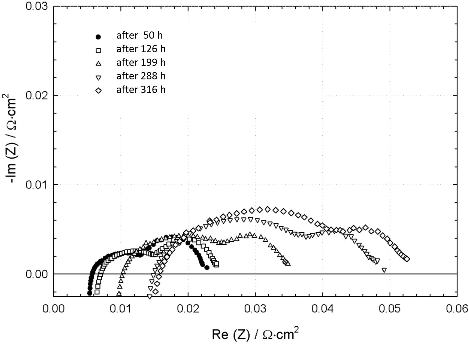
Figure 1. Electrochemical impedance spectra of the reverse MCFC cell taken under an electrolysis current of 150 mA/cm2 and at various times during the alternated period of testing (T = 650°C; fuel electrode gas composition of 25CO2/25H2O/25H2/25N2 and oxygen electrode gas composition of 25CO2/25O2/50N2).
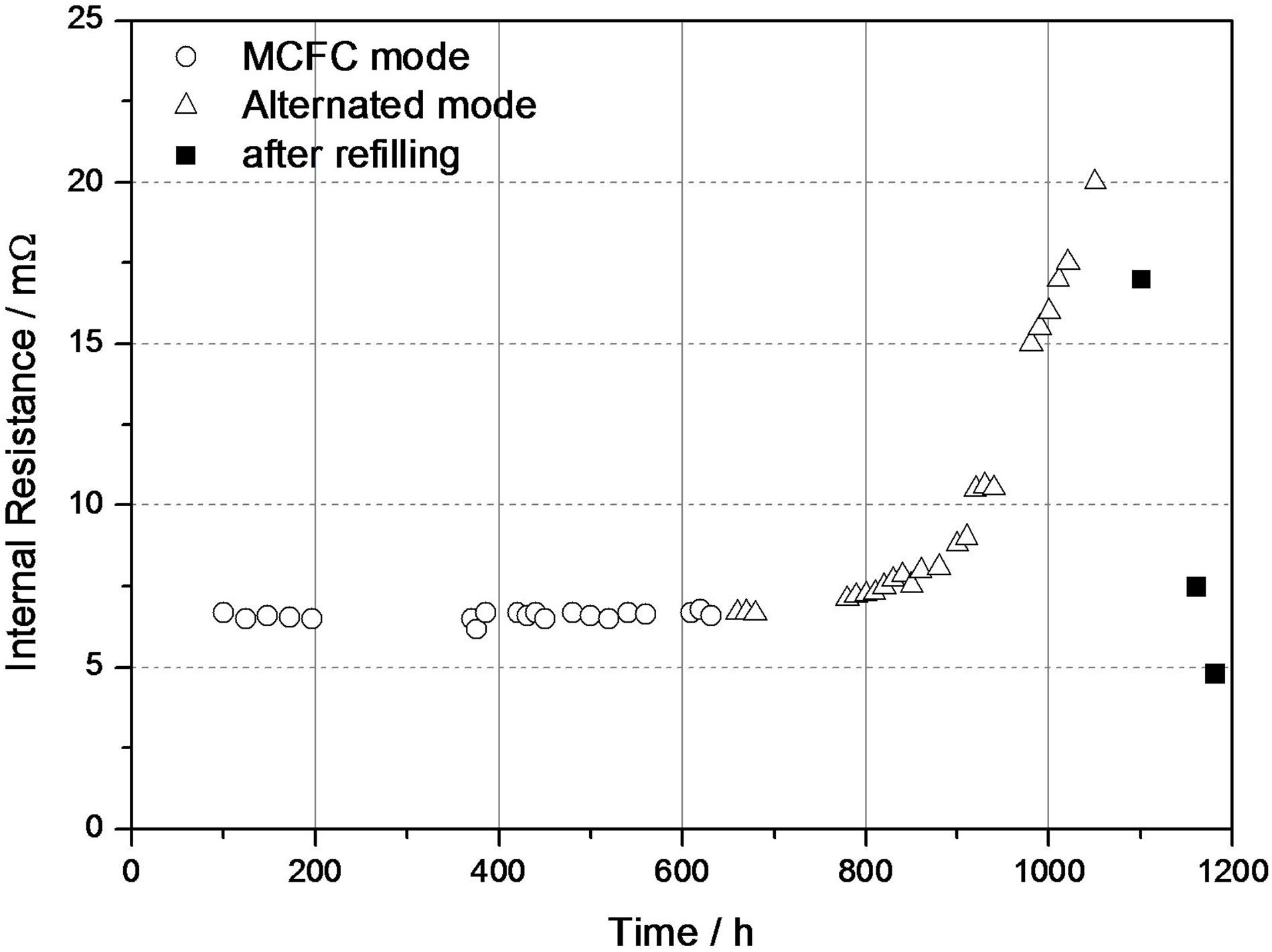
Figure 2. Evolution of internal ohmic resistance in the reverse MCFC cell during the fuel cell and the alternated periods of testing. Resistance data taken during the refilling period at the end of the testing campaign are also reported.
EIS measurements indicated no appreciable change in internal resistance after a first addition with the cell set at OCV. Further electrolyte was added in two subsequent attempts but with the difference that the cell in the latter cases was kept under current load during the refilling and for the subsequent hours. The most significant resistance drop was obtained when refilling was done under a load of 0.8 A and leaving the cell under 2.4 A for the subsequent 24 h. After that, the cell internal resistance showed, in fact, a drastic drop, decreasing 11 mΩ, from 16.6 mΩ to ca. 5 mΩ. Although not fully understood, this result could be explained by assuming that current flow is an important factor that enhances electrolyte wetting in reversed MCFC electrodes. It was also observed that during the refilling period the impedance at low frequency region of the EIS spectrum (results not reported here) remained always higher than at beginning of the reversible mode test, thereby suggesting that other causes besides electrolyte evaporation could be responsible for the electrode polarization degradation.
Post-mortem Analysis
After the completion of the bench-scale tests, the degradation of MCFC materials was investigated by XRD and SEM/EDX analysis. The effect of the alternated operation on the XRD spectra of oxygen and fuel electrodes is shown in Figures 3, 4, respectively. In the Figure 3 only minor changes in the phase composition of the oxygen electrode are appreciable in comparison to the reference test electrode. The NiO(Li) phase structure of the oxygen electrode is largely preserved during the alternated operation, although peaks of a minor oxide phase are also visible at ca. 19 and 37°. These minor peaks provide evidence of the formation of a Li-Ni-O phase, which was tentatively attributed to LiNiO2 (JCPDS Card 09-0063) (Kalyani and Kalaiselvi, 2005). The subtle set of multiple peaks located in the region 30–35° is the result of some lithium carbonate present as residual salt. In spite of such minor differences in phase composition, the alternated operation produced great changes in the mechanical stability of the oxygen electrode. Rapid degradation of the electrode mass into powder during the aqueous cleaning treatment was observed only in the case of the alternated cell electrode, which was taken as a clear indication of the dramatic loss of mechanical stability in comparison to the reference test electrode. The XRD pattern of the fuel electrodes are reported in Figure 4. No appreciable effect of alternated operation can be observed on the phase composition of the fuel electrode. The typical diffraction pattern of the phase-centered cubic phase of metallic nickel is invariably seen in both the cases. Although higher steam concentrations are present at the fuel electrode during electrolysis, no trace of nickel oxide formation could be found in the XRD pattern of the alternated cell electrode. Similarly, no obvious difference in mechanical properties with the reference test fuel electrode could be detected during the aqueous cleaning treatment.
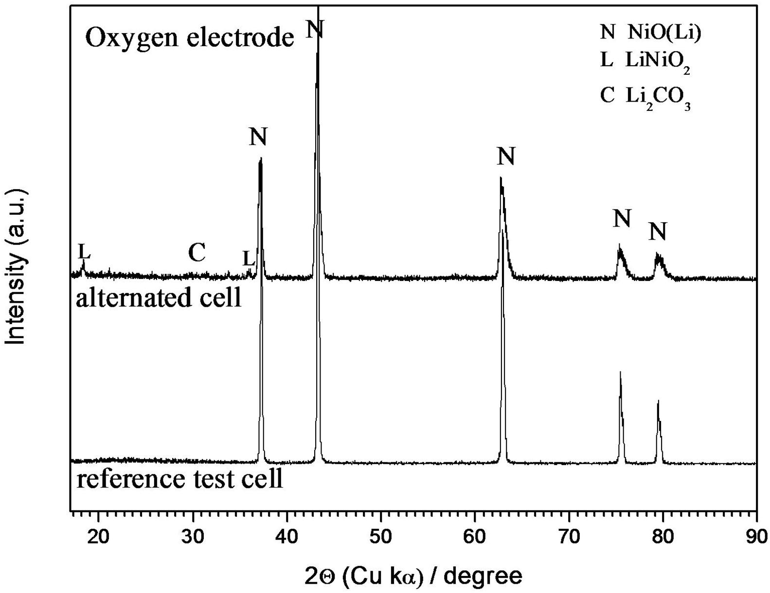
Figure 3. XRD patterns of the spent NiO oxygen electrode in reverse and reference test MCFC cells.
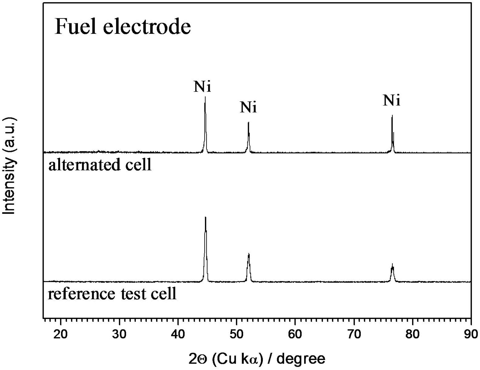
Figure 4. XRD patterns of the spent Ni-Al alloy fuel electrode in reverse and reference test MCFC cells.
Figure 5 shows the SEM micrographs of the spent oxygen electrodes at two different magnifications. The Figures 5b,d refers to the reference test electrode and show the typical agglomerate structure of a MCFC oxygen electrode, which is characterized by a bimodal pore size distribution with appropriate amounts of macropores for the gas diffusion (6–7 μm average diameter size) and micropores for the electrochemical reaction (<1 μm diameter size). It can be seen that the agglomerate structure is significantly altered by the alternated operations (Figures 5a,c). A reduced average pore size of the alternated cell electrode is clearly observable, which is caused by a sharp decrease in the size and number of macropores. Differently, the size of micropores remained essentially unaltered and almost the same as those of the baseline MCFC electrode.
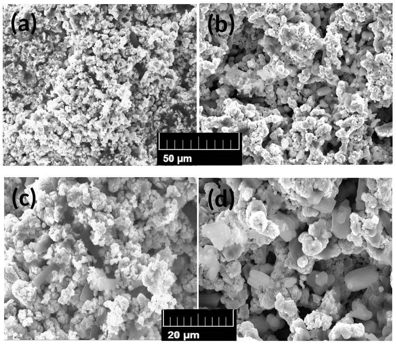
Figure 5. SEM micrographs of the spent NiO oxygen electrodes at two different magnifications: (a–c) electrode structure of the reverse MCFC cell; (b–d) electrode structure of the reference test cell.
The morphology of the nickel metal fuel electrodes is shown in Figure 6. It can be seen that electrolysis gives raise to significant alteration of the agglomerate structure. Similarly to the oxygen electrode case, the size and number of macropores dramatically decreased during alternated operation. This was also accompanied by a particle shape that changed from the rounded cubic grains, which is typical of conventional MCFC fuel electrodes (Figure 6b) to an elongated particle shape accompanied also to some increase in size of the particles (Figure 6a).
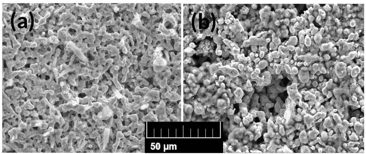
Figure 6. SEM micrographs of the spent fuel Ni-Al alloy electrodes: (a) electrode structure of the reverse MCFC cell; (b) electrode structure of the reference test cell.
Nickel dissolution/precipitation and corrosion of the steel current collectors are two well-known factors affecting performance and lifetime of routine MCFC cells. For this reason, distribution of nickel and chromium was analyzed in the electrolyte matrix along the fuel-to-oxygen electrode section. SEM cross-sections of the matrix of the alternated and of the reference test cell are reported in Figures 7a,b, respectively. The arrows indicate the position of the EDX line scans. Although no obvious difference in matrix microstructure could be observed, distinct variations between the two samples were found for what is concerned the distribution of the two elements, especially of nickel, as observable by the EDX line scan results of Figure 8. An evident increase of nickel average concentration is visible along the entire section of the alternated cell matrix. Several spikes in nickel concentration likely due to abundant nickel particle precipitation are also clearly visible. Further, looking at the position of the spikes, the precipitation region appears wide and well extending toward the fuel electrode region. In comparison, spikes are less intense and much less numerous in the MCFC matrix suggesting minor precipitation phenomena. Less relevant differences can be observed for what is concerned chromium distribution in the matrix. It is worth underlining that stainless steel current collectors are the main source of chromium in the matrix with the major effect expected from the oxygen current collector, where the oxidizing environment conditions cause increased formation of chromium oxide and its dissolution as soluble chromate in the electrolyte. In spite of it, chromium concentration is distinctly higher at the fuel electrode side in both the samples as visible from Figure 8 thus indicating that chromium migration comes predominantly from the fuel current collector. This result is not fully understood, since it appears in contradiction with the considerations mentioned above. However, it may have something to do with the fact that the bench-scale cells were assembled with bare steel fuel collectors and not with the more corrosion-resistant nickel-coated collectors as generally employed in real-life MCFC systems. Thus, in absence of a protective coating, some hot corrosion fluxing reactions might have occurred (Yuh et al., 1995; Frangini, 2008) causing enhanced chromium release in the matrix from the fuel collector side. Although the utilization of bare fuel steel collectors added an artifact to the cell assembly, it was nonetheless useful to show that alternated operations had only a marginal effect on the chromium dissolution at the fuel matrix side, as can be clearly seen in Figure 8.
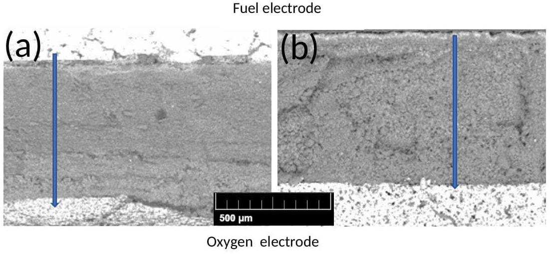
Figure 7. SEM micrographs of the matrix cross-section in: (a) reverse MCFC cell and (b) reference test cell.
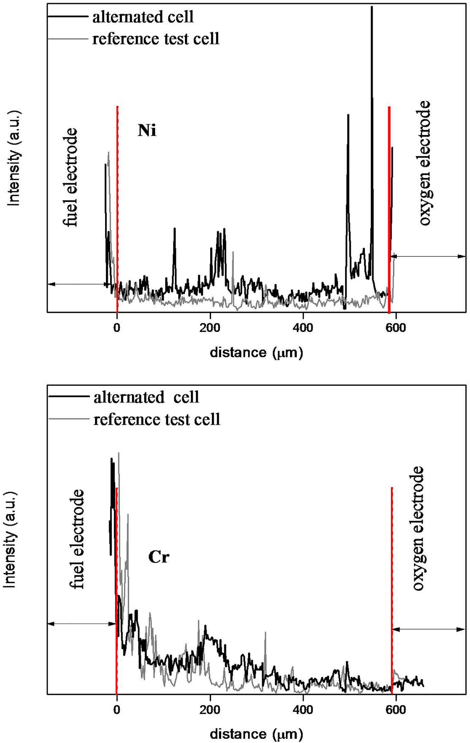
Figure 8. EDX elemental analysis distribution of Cr and Ni across the matrix cross-section of reverse and reference test cells.
Discussion
The results of this work undoubtedly indicate that bench-scale experiments are more idoneous than coin-cell tests for materials degradation studies of MCFC cell components. Thus, it has been shown that conventional MCFC electrode materials become more unstable and reactive in molten carbonate when operating under alternated conditions. Electrode microstructure degraded rapidly for alternated operation times as short as a few hundreds of hours, which is in agreement with the impedance electrochemical results shown in Figure 1. As already mentioned in the Introduction, the degradation of steel current collectors was also examined. Focusing our attention only to the oxygen current collector, since the material of construction is the same as that used in real-life MCFC systems, visual magnification was sufficient to reveal the dramatic corrosion of the oxygen current collector under alternated operation as observable in Figure 9. The evident heavy corrosion with disintegration of the component structure in the central part may have contributed along with electrolyte evaporation to the observed rapid and continuous increase of internal ohmic resistance of the cell during the alternated operation period, thus indicating that bare steels cannot be used under such conditions.
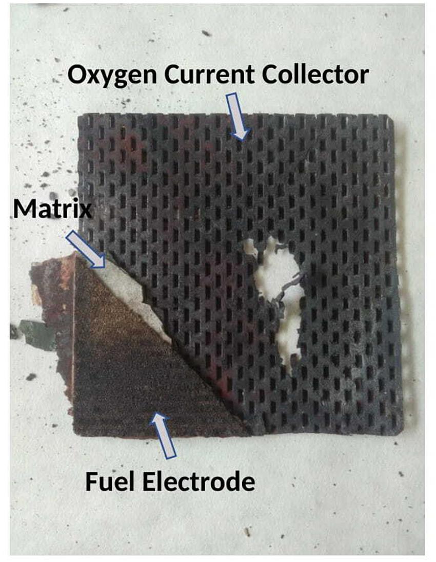
Figure 9. Photograph showing the corrosion of the 316L steel oxygen current collector after the reverse MCFC cell testing.
Coating protection by ceramic spinel or perovskite oxides is commonly applied to Solid Oxide Fuel Cell stainless steel interconnectors for suppressing performance degradation at air side. Similar spinel and perovskite coatings have been also studied for MCFC collectors, although coating protection at air side is rarely used in practice, due to a satisfactory performance of bare austenitic stainless steels under the strictly-controlled MCFC operating conditions of commercial stacks. According to Frangini (2008), best combination of protection and functional properties have been obtained with LiCoO2 and La0.8Sr0.2CoO3 layers applied with sol-gel methods. Surface chemical modification treatments have been also investigated as alternative to coating deposition methods. In particular, good protective results on MCFC steels have been also obtained with LaFeO3 layers formed by conversion coating reactions of the steel surface with La2O3 in specially-formulated molten salts (Frangini et al., 2011, 2012).
As aforementioned, the post-mortem analysis has evidenced significant degradation of the conventional MCFC electrodes induced by the alternated operation. Degradation of MCFC electrodes and, in particular, dissolution stability of the conventional NiO oxygen electrode is well known as one of the most critical lifetime-limiting factor in MCFC technology. This derives from the fact that during the fuel cell operation the dissolved Ni migrates toward the reducing region of the matrix, where it may precipitate as metal Ni particles forming bridged conductive paths, which will eventually lead to short-circuit failure of the cell (Kulkarni and Giddey, 2012). Our results indicate that such electrode stability problems are further aggravated under the alternate mode of operation suggesting that alternative electrode materials should be developed for stable bifunctional MCFC oxygen electrodes. Based on available literature, some possible directions for materials development are suggested.
The excellent stability over a wide range of molten carbonate conditions poses ceramic oxides as ideal candidates for the fabrication of bifunctional electrodes resistant to sintering and to chemical dissolution effects. It is worth mentioning that the search for ceramic materials as alternative to the routine NiO electrode is not a new topic having already been intensively investigated in the 80’s during the first wave of MCFC technological development (Baumgartner et al., 1984; Makkus et al., 1994). Attention at that time was focused in particular on LiFeO2 and LiCoO2 ceramic oxides for their favorable chemical stability and low dissolution properties, although only LiCoO2 cathodes was found to exhibit also an electronic conductivity comparable to NiO. However, the production of tape sheets with these ceramic materials was proved a challenge to implement at industrial scale due to various technical issues (Lagergren et al., 1994) resulting thus in a gradual fading of interest after the initial enthusiasm.
In a recent return of interest, practical use of ceramics has been proposed yet in form of protective coatings following two different routes of electrode coating application (Kulkarni and Giddey, 2012). In a simpler approach, several studies focused on applying a ceramic coating of various cobalt oxides directly onto the surface of tape casted NiO electrode sheets by using dip coating techniques (Kuk et al., 2001; Ganesan et al., 2003; Mendoza et al., 2005; Paoletti et al., 2009; Song et al., 2019). Since geometrical protection does not diminish the NiO solubility, but only its dissolution rate, some authors investigated also the possibility of producing composite powders with a core-shell structure as an alternative coating route for a more durable protection. Avoiding additional processing steps and reducing the risks associated with handling of the fragile large area tapes at industrial scale were identified as further practical advantages. According to Fukui et al. (2003) and Okawa et al. (2004), coated electrode particles were prepared by coating the surface of the routine NiO powder with a thin layer of stable ceramic material such as LiCoO2 or MgFe2O4 using special mechanical mixers that allow preservation of the pristine NiO filament structure. In particular, NiO core/MgFe2O4 shell electrode structures demonstrated superior chemical stability in molten carbonate being able to reduce Ni dissolution to one-fourth of that of routine NiO electrode (Okawa et al., 2004). The cell performance of the NiO core/MgFe2O4 shell tape electrode was also tested in 100 cm2 single cells. Minimal voltage degradation effects were found during a period of 5,000 h testing at 650°C in comparison to cells using uncoated NiO electrodes (Okawa et al., 2004). Alternative methods for synthesis of core/shell electrodes have been also investigated by Korean researchers (Lee et al., 2003, 2004; Park et al., 2005; Kim et al., 2006, 2011). The solubility of Co/Ce coated Ni powders prepared by a sol-gel Pechini process has been reported to be about 80% lower in comparison to a routine NiO cathode under 67CO2–33O2 atmosphere at 650°C (Kim et al., 2006). In a subsequent paper, a lithiated Ni0.9Co0.1O solid solution powder with a core/shell structure formed in situ after oxidation at 650°C of ball milled Ni and Co3O4 powders was analyzed (Kim et al., 2011). Improved dissolution stability and high electrochemical properties were found at level of pellet-type electrodes, which was ascribed to the highly lithiated outer shell.
Although it is not clear which synthesis method may offer the best results, there is no doubt that improved chemical stability and low dissolution can be reached with the use of core-shell particle electrode structures. Taking also note that many efficient bifunctional electrocatalysts are today based on core/shell structures (Strasser et al., 2010; Chen et al., 2018; Jiang et al., 2018), it is believed that such composite powder materials should be taken into serious consideration for the design of stable and efficient MCFC bifunctional oxygen (but also fuel) electrodes.
Conclusion
In order to possibly expand the application uses of electrochemical MCFC systems, a 81 cm2 single cell assembled with conventional MCFC materials was operated as alternated fuel cell/electrolysis cell at 650°C, in a binary Li2CO3–K2CO3 electrolyte. Materials degradation was compared against a single cell operated in only fuel cell mode under similar operating conditions. The conventional MCFC materials used for single cell assembly consisted of a NiO(Li) oxygen electrode, a γ-AlLiO2 matrix, a Ni-Al alloy fuel electrode and bare current collectors made of 316L stainless steel.
A rapid cell degradation was recorded as soon as the cell started to work in alternated mode after an initial period of 650 h in which the cell operated stably in the usual fuel cell mode. A continuous and rapid increase in both internal resistance and electrode polarization was observed during ca. 400 h of alternated operation mode. Since partial recovery of cell performance was obtained by electrolyte refilling, electrolyte evaporation was assumed as one possible degradation factor of the cell performance. After test completion, a comparative post-mortem analysis was conducted on the cell materials to individuate other possible causes of the accelerated cell degradation performance. Thus, a dramatic corrosion of the 316L stainless steel oxygen current collector could be detected by mere visual examination after cell dismantling, which was considered an additional cause for the increase of cell internal resistance observed during the alternated operation period. A detailed analysis with SEM/EDX and XRD was also conducted to evaluate degradation of the active cell materials. Although the electrolyte matrix appeared almost unaffected, evident signs of accelerated structural degradation in both fuel and oxygen electrodes were found as a result of the alternated mode of operations. Additionally, higher presence of dissolved Ni in the matrix indicated also an increasing chemical instability of the oxygen electrode induced by the reversible operation. Based on available literature, some research directions to improve stability of conventional electrodes and current collectors in reverse MCFC cells have been suggested based on the development of advanced surface modification and coating technologies. In particular, core-shell particle structures, in which the conventional NiO electrode particles are covered by a protective and stable thin film of LiCoO2 or MgFe2O4 ceramic oxides, seems the most promising approach to produce stable reversible oxygen electrodes. Similarly, for effective coating protection of the stainless steel oxygen current collectors in electrolysis or alternated MCFC cells, spinel and perovskite oxides based on LiCoO2, La0.8Sr0.2CoO3, or LaFeO3 compositions should be considered.
Data Availability Statement
The raw data supporting the conclusions of this article will be made available by the authors, without undue reservation.
Author Contributions
SF conceived the proposal of this manuscript and wrote the original draft. MD and JP were responsible for the electrochemical investigation. LD carried out SEM/EDX analysis. CP carried out XRD analysis. All authors gave suggestions to the manuscript and approved the submitted version.
Funding
This work was financially supported by the Italian Ministry of Economic Development through the Electrical System Research programme-PTR 2019-21-Objective: Technologies-Project 1.2/WP3.
Conflict of Interest
The authors declare that the research was conducted in the absence of any commercial or financial relationships that could be construed as a potential conflict of interest.
References
Baumgartner, C. E., Arendt, R. H., Iacovangelo, C. D., and Karas, B. R. (1984). Molten carbonate fuel cell cathode materials study. J. Electrochem Soc. 131, 2217–2220. doi: 10.1149/1.2115228
Chen, M., Wang, L., Yang, H., Zhao, S., Xu, H., and Wu, G. (2018). Nanocarbon/oxide composite catalysts for bifunctional oxygen reduction and evolution in reversible alkaline fuel cells: a mini review. J. Power Sources 375, 277–290. doi: 10.1016/j.jpowsour.2017.08.062
Frangini, S. (2008). Corrosion of metallic stack components in molten carbonates: critical issues and recent findings. J. Power Sources 182, 462–468. doi: 10.1016/j.jpowsour.2007.11.100
Frangini, S., Masci, A., and Zaza, F. (2011). Molten salt synthesis of perovskite conversion coatings: a novel approach for corrosion protection of stainless steels in molten carbonate fuel cells. Corros Sci. 53, 2539–2548. doi: 10.1016/j.corsci.2011.04.011
Frangini, S., Zaza, F., and Masci, A. (2012). Molten carbonate corrosion of a 13-Cr ferritic stainless steel protected by a perovskite conversion treatment: relationship with the coating microstructure and formation mechanism. Corros Sci. 62, 136–146. doi: 10.1016/j.corsci.2012.05.011
Fukui, T., Ohara, S., Okawa, H., Naito, M., and Nogi, K. (2003). Synthesis of metal and ceramic composite particles for fuel cell electrodes. J. Eur. Ceram Soc. 23, 2835–2840. doi: 10.1016/S0955-2219(03)00296-6
Ganesan, P., Colon, H., Haran, B., and Popov, B. N. (2003). Performance of La0.8Sr0.2CoO3 coated NiO as cathodes for molten carbonate fuel cells. J. Power Sources 115, 12–18. doi: 10.1016/S0378-7753(02)00621-3
Götz, M., Lefebvre, J., Mörs, F., McDaniel Koch, A., Graf, F., Bajohr, S., et al. (2016). Renewable Power-to-Gas: a technological and economic review. Renew Energy 85, 1371–1390. doi: 10.1016/j.renene.2015.07.066
Hu, L., Lindbergh, G., and Lagergren, C. (2015a). Electrode kinetics of the Ni porous electrode for hydrogen production in a molten carbonate electrolysis cell (MCEC). J. Electrochem. Soc. 162, F1020–F1028. doi: 10.1149/2.0491509jes
Hu, L., Lindbergh, G., and Lagergren, C. (2015b). Electrode kinetics of the NiO porous electrode for oxygen production in the molten carbonate electrolysis cell (MCEC). Faraday Dis. 182, 493–509. doi: 10.1039/c5fd00011d
Hu, L., Lindbergh, G., and Lagergren, C. (2016a). Operating the nickel electrode with hydrogen-lean gases in the molten carbonate electrolysis cell (MCEC). Int. J. Hydrogen Energy 41, 18692–18698. doi: 10.1016/j.ijhydene.2016.06.037
Hu, L., Lindbergh, G., and Lagergren, C. (2016b). Performance and durability of the molten carbonate electrolysis cell and the reversible molten carbonate fuel cell. J. Phys. Chem. C 120, 13427–13433. doi: 10.1021/acs.jpcc.6b04417
Hu, L., Rexed, I., Lindbergh, G., and Lagergren, C. (2014). Electrochemical performance of reversible molten carbonate fuel cells. Int. J. Hydrogen Energy 39, 12323–12329. doi: 10.1016/j.ijhydene.2014.02.144
Jiang, R., Tung, S., Tang, Z., Li, L., Ding, L., Xi, X., et al. (2018). A review of core-shell nanostructured electrocatalysts for oxygen reduction reaction. Energy Storage Mater. 12, 260–276. doi: 10.1016/j.ensm.2017.11.005
Kalyani, P., and Kalaiselvi, N. (2005). Various aspects of LiNiO2 chemistry: a review. Sci. Technol. Adv. Mater. 6, 689–703. doi: 10.1016/j.stam.2005.06.001
Kim, M. H., Hong, M. Z., Kim, Y. S., Park, E., Lee, H., Ha, H. W., et al. (2006). Cobalt and cerium coated Ni powder as a new candidate cathode material for MCFC. Electrochim. Acta 51, 6145–6151. doi: 10.1016/j.electacta.2006.01.073
Kim, Y. S., Yi, C. W., Choi, H. S., and Kim, K. (2011). Modification of Ni-based cathode material for molten carbonate fuel cells using Co3O4. J. Power Sources 196, 1886–1893. doi: 10.1016/j.jpowsour.2010.08.086
Kuk, S. T., Song, Y. S., Suh, S., Kim, J. Y., and Kim, K. (2001). The formation of LiCoO2 on a NiO cathode for a molten carbonate fuel cell using electroplating. J. Mater. Chem. 11, 630–635. doi: 10.1039/b003972l
Kulkarni, A., and Giddey, S. (2012). Materials issues and recent developments in molten carbonate fuel cells. J. Solid State Electrochem. 16, 3123–3146. doi: 10.1007/s10008-012-1771-y
Lagergren, C., Lundblad, A., and Bergman, B. (1994). Synthesis and performance of LiCoO2 cathodes for the molten carbonate fuel cell. J. Electrochem. Soc. 141, 2959–2966. doi: 10.1149/1.2059265
Lee, H., Hong, M., Bae, S., Lee, H., Park, E., and Kim, K. (2003). A novel approach to preparing nano-size Co3O4-coated Ni powder by the Pechini method for MCFC cathodes. J. Mater. Chem. 13, 2626–2632. doi: 10.1039/b303980c
Lee, H. S., Hong, M. Z., Park, E. J., and Kim, K. (2004). Phase changes of newly synthesized Co-coated Ni cathode in MCFC cathodic conditions. J. Mater. Sci. 39, 5595–5598. doi: 10.1023/B:JMSC.0000039297.35715.2d
Licht, S., and Wu, H. (2011). STEP iron, a chemistry of iron formation without CO 2 emission: molten carbonate solubility and electrochemistry of iron ore impurities. J. Phys. Chem. C 115, 25138–25147. doi: 10.1021/jp2078715
Makkus, R. C., Hemmes, K., and de Wit, J. H. W. (1994). A comparative study of NiO (Li), LiFeO2, and LiCoO2 porous cathodes for molten carbonate fuel cells. J. Electrochem. Soc. 141, 3429–3438. doi: 10.1149/1.2059349
McVay, D., Zhao, L., Brouwer, J., Jahnke, F., and Lambrech, M. (2017). “A spatially resolved physical model for dynamic modeling of a novel hybrid reformer-electrolyzer-purifier (REP) for production of hydrogen,” in In Proceeding of the ASME 2017 11th Int. Conf. Energy Sustain. ES 2017, Collocated with ASME 2017 Power Conf. Jt. with ICOPE 2017, ASME 2017 15th Int. Conf. Fuel Cell Sci. Eng. Technol. ASME 201, (ASME).
Mendoza, L., Ringuedé, A., Cassir, M., and Galtayries, A. (2005). II. Structural, morphological, chemical and electrochemical analysis of nickel covered by electrochemically deposited Co3O4 in molten Li2CO3-Na2CO3 at 650 °c. J. Electroanal. Chem. 576, 147–160. doi: 10.1016/j.jelechem.2004.09.033
Mogensen, M. B. (2020). Materials for reversible solid oxide cells. Curr. Opin. Electrochem. 21, 265–273. doi: 10.1016/j.coelec.2020.03.014
Nguyen, V. N., and Blum, L. (2016). “Reversible fuel cells,” in Frano Barbir, Angelo Basile TNV, ed. C. Hydrog (Cambridge: Woodhead Publishing), 115–145.
Okawa, H., Lee, J. H., Hotta, T., Ohara, S., Takahashi, S., Shibahashi, T., et al. (2004). Performance of NiO/MgFe2O4 composite cathode for a molten carbonate fuel cell. J. Power Sources 131, 251–255. doi: 10.1016/j.jpowsour.2003.11.092
Paoletti, C., Carewska, M., Presti, R., Phail, S. M., Simonetti, E., and Zaza, F. (2009). Performance analysis of new cathode materials for molten carbonate fuel cells. J. Power Sources 193, 292–297. doi: 10.1016/j.jpowsour.2008.12.094
Park, E., Hong, M., Lee, H., Kim, M., and Kim, K. (2005). A new candidate cathode material as (Co/Mg)-coated Ni powder for molten carbonate fuel cell. J. Power Sources 143, 84–92. doi: 10.1016/j.jpowsour.2004.11.031
Perez-Trujillo, J. P., Elizalde-Blancas, F., Della Pietra, M., and McPhail, S. J. (2018). A numerical and experimental comparison of a single reversible molten carbonate cell operating in fuel cell mode and electrolysis mode. Appl. Energy 226, 1037–1055. doi: 10.1016/j.apenergy.2018.05.121
Pérez-Trujillo, J. P., Elizalde-Blancas, F., McPhail, S. J., Della Pietra, M., and Bosio, B. (2020). Preliminary theoretical and experimental analysis of a Molten Carbonate Fuel Cell operating in reversible mode. Appl. Energy 263:114630. doi: 10.1016/j.apenergy.2020.114630
Selman, J. R., and Marianowski, L. G. (1982). “Fuel Cells,” in Molten Salt Technol, ed. D. G. Lovering (New York, NY: Plenum Press).
Song, S. A., Kim, H. T., Kim, K., Lim, S. N., Yoon, S. P., and Jang, S. C. (2019). Effect of LiNiO2-coated cathode on cell performance in molten carbonate fuel cells. Int. J. Hydrogen Energy 44, 12085–12093. doi: 10.1016/j.ijhydene.2019.03.080
Strasser, P., Koh, S., Anniyev, T., Greeley, J., More, K., Yu, C., et al. (2010). Lattice-strain control of the activity in dealloyed core – shell fuel cell catalysts. Nat. Chem. 2, 454–460. doi: 10.1038/nchem.623
Thema, M., Bauer, F., and Sterner, M. (2019). Power-to-Gas: electrolysis and methanation status review. Renew Sustain Energy Rev. 112, 775–787. doi: 10.1016/j.rser.2019.06.030
United Nations Environment Programme [UNEP] (2019). Emissions Gap Report 2019, United Nations Environment Programme, Nairobi, Kenia. Available online at: http://www.unenvironment.org/emissionsgap (accessed December 9, 2020).
Verda, V., and Sciacovelli, A. (2011). Design improvement of circular molten carbonate fuel cell stack through CFD Analysis. Appl. Therm. Eng. 31, 2740–2748. doi: 10.1016/j.applthermaleng.2011.04.046
Wang, Y., Leung, D. Y. C., Xuan, J., and Wang, H. (2016). A review on unitized regenerative fuel cell technologies, part-A: unitized regenerative proton exchange membrane fuel cells. Renew Sustain Energy Rev. 65, 961–977. doi: 10.1016/j.rser.2016.07.046
Wang, Y., Leung, D. Y. C., Xuan, J., and Wang, H. (2017). A review on unitized regenerative fuel cell technologies, part B: unitized regenerative alkaline fuel cell, solid oxide fuel cell, and microfluidic fuel cell. Renew Sustain Energy Rev. 75, 775–795. doi: 10.1016/j.rser.2016.11.054
Yuh, C., Johnsen, R., Farooque, M., and Maru, H. (1995). Status of carbonate fuel cell materials. J. Power Sources 56, 1–10. doi: 10.1016/0378-7753(95)80001-W
Keywords: molten carbonate fuel cell, post-mortem analysis, materials degradation, coating protection, core-shell electrodes, reverse cell
Citation: Frangini S, Della Pietra M, Della Seta L, Paoletti C and Pedro Pérez-Trujillo J (2021) Degradation of MCFC Materials in a 81 cm2 Single Cell Operated Under Alternated Fuel Cell/Electrolysis Mode. Front. Energy Res. 9:653531. doi: 10.3389/fenrg.2021.653531
Received: 14 January 2021; Accepted: 12 April 2021;
Published: 29 April 2021.
Edited by:
Timothy A. Barckholtz, ExxonMobil, United StatesReviewed by:
Ermete Antolini, Scuola Scienza Materiali, ItalyHossein Ghezel-Ayagh, FuelCell Energy, United States
Copyright © 2021 Frangini, Della Pietra, Della Seta, Paoletti and Pedro Pérez-Trujillo. This is an open-access article distributed under the terms of the Creative Commons Attribution License (CC BY). The use, distribution or reproduction in other forums is permitted, provided the original author(s) and the copyright owner(s) are credited and that the original publication in this journal is cited, in accordance with accepted academic practice. No use, distribution or reproduction is permitted which does not comply with these terms.
*Correspondence: Stefano Frangini, stefano.frangini@enea.it