Numerical Simulation of Transient Characteristics of Start-Up Transition Process of Large Vertical Siphon Axial Flow Pump Station
 Xiaowen Zhang
 Fangping Tang*
 - College of Hydraulic Science and Engineering, Yangzhou University, Yangzhou, China
In order to explore the transient characteristics of the large-scale vertical siphon axial flow pumping station during the start-up and exhaust process, numerical simulations were carried out on the start-up process of the axial flow pumping station under the two starting modes of pre-opening the vacuum breaking valve and keeping the vacuum breaking valve closed. The calculation results show that during the start-up phase of the unit, the flow separation phenomenon of the impeller channel of the pump device with the vacuum breaking valve closed is serious, the large-scale vortex in the guide vane blocks the flow channel, and the instantaneous impact on the blade surface is strong. The flow field of the pump device with pre-open vacuum failure valve is obviously less affected by the instantaneous impact characteristics during the start-up of the pump. The range of high entropy production area in the impeller channel is reduced, the duration of high entropy production area is significantly shortened, and the instantaneous impact on the blade surface is weak. Under the two starting modes, the internal flow field of the pump device is similar in the evolutionary law. The unstable flow phenomenon of the pump device is most prominent in the weir flow stage. The maximum instantaneous impact on the blade surface also mainly occurs in the weir flow stage. A very small part of the remaining gas in the siphon formation stage is difficult to discharge and takes a long time. After the pump device is exhausted and enters a stable operation state, the external characteristic parameters are in good agreement with the test results. Compared with the starting method in which the vacuum breaking valve is kept closed, the method of pre-opening the vacuum breaking valve reduces the maximum starting head by 20% and the exhaust time by 43%. The pre-open vacuum breaking valve effectively avoids the system instability caused by the start-up and exhaust of the pump device.
Introduction
Pumping stations are widely used in urban drainage, inter-basin water transfer and agricultural irrigation (Wang et al., 2010; Xie et al., 2018; Intriago Zambrano et al., 2019). Due to the convenience and reliability of the siphon outlet channel, the siphon outlet channel is often selected in the large and medium-sized vertical axial flow pumping stations in my country. With the development and application of pumping stations, the transient characteristics in the transition process of pumping stations have attracted more and more attention and become an important factor restricting the safe and stable operation of pumping stations.
In recent years, domestic and foreign scholars have done a lot of research on the transient characteristics of hydraulic machinery. At present, there are many methods to study the transient process of hydraulic machinery, including experimental test, one-dimensional characteristic method and three-dimensional computational fluid dynamics simulation (Jintao et al., 2013; Zhou et al., 2017; Li et al., 2019; Yang et al., 2020; Zhang et al., 2021). Among the three methods, experiment is the most direct way to obtain data. However, it often requires a lot of manpower and material resources, and most of the transient processes are dangerous. Tsukamoto and Ohashi (Tsukamoto and Ohashi, 1982) theoretically deduced and experimentally verified the transient characteristics of centrifugal pump in the process from static to acceleration to stability. The evolution law of dynamic characteristics during turbine pump starting process is revealed. They pointed out that the impact pressure around the impeller blade causes the deviation of the dynamic and quasi-steady characteristics of the turbine pump during the acceleration process. Li et al. (2011) studied the transient characteristics of centrifugal pump start-up acceleration by using two-dimensional image particle velocity measurement technology and sliding mesh method. It was found that the transient vortex between centrifugal pump blades over time was the main reason for the transient head coefficient of the pump being lower than the steady value during the start-up process. Lefebvre and Barker (1995) studied the transient hydraulic performance of centrifugal pump through experiments and compared it with the quasi-steady state assumption. They found that the overall performance of the impeller had a significant transient effect, and proved that the quasi-steady state assumption was not suitable for the impeller running under high transient conditions. Zhang et al. (2020) studied the transient hydraulic performance of self-priming clear water pump under fast and slow start-up conditions. They found that the similarity law of the pump is particularly not suitable for the first half of the startup process when the steady-state flow is small, nor for the second half of the startup process when the steady-state flow is large.
One-dimensional characteristic method and three-dimensional computational fluid dynamics simulation can simulate and predict the internal flow field of hydraulic machinery. Compared with the one-dimensional characteristic method, the three-dimensional computational fluid dynamics simulation method can obtain more comprehensive and detailed flow field structure and flow information. Therefore, CFD method is currently a better choice for studying the transient flow characteristics of hydraulic machinery. Li et al. (2018) used 3D-CFD method to solve the two-way fluid-solid coupling of the mixed flow pump in the start-up acceleration process. They found that the maximum stress value of the impeller appeared at the outlet edge of the impeller near the hub during the start-up of the mixed-flow pump, and the instantaneous fluid shock at the hub may lead to the sudden fracture of the blade. Fu et al. (2020), Hu et al. (2012) used the dynamic mesh method (DM) to simulate the internal flow field characteristics of centrifugal pump during the start-up process. It was found that the axial vortex in the impeller was born at the outlet pressure side during the start-up process, and moved to the middle channel of the impeller over time. The vortex intensity of the axial vortex increased first and then decreased. Wu et al. (2010) studied the transient characteristics of the nuclear main pump system during the rapid opening of the valve based on the detached eddy simulation (DES) method. It was found that the performance of the pump during the rapid opening of the valve was affected by the fluid acceleration and the instantaneous evolution of the vortex structure, and the Q-H curve of the nuclear main pump system deviated from the steady state value. At the same time, the 3D-CFD method also shows the superiority for the calculation of hydraulic machinery transient process combined with multiphase. Liu et al. (2011) used the fluid volume method (VOF) combined with the dynamic mesh method to numerically study the rapid pump stop process of the pump system. The numerical results are highly consistent with the experimental results. They pointed out that the difference between the transient external characteristics and the steady-state external characteristics in the pump stop process is caused by the evolution of the eddy current in the impeller. Ahn et al. (2017) used two-phase flow numerical model to study the influence of surface vortex on the operation conditions of tidal energy units. It was found that the strong surface vortex in the reservoir and the high gas content in the water caused the fluctuation of the intake flow of the tidal energy units, which was easy to induce the instability of the intake pipeline. In recent years, the use of 3D-CFD to study the transient mechanical transition process has been involved in centrifugal pump and pump turbine, and the study of axial flow pump system is rarely. Fu et al. (2020) conducted numerical simulation and experimental verification of the startup process of axial flow pump system with two fast flap gates by using dynamic mesh technology. It was found that there was a large area of vortex core in the leading edge of the blade and the impeller passage during the startup process of axial flow pump system. The instantaneous impact head of the pump system reached the maximum when the impeller speed reached the rated speed. Kan et al. (2021) used fluid volume method (VOF) and rigid cover hypothesis method (RLH) to predict the transient characteristics of the system during power outage. It was found that VOF method is more accurate in predicting transient characteristics of axial flow pump units under water-air interaction. The maximum runaway speed calculated by numerical method agrees well with the experiment.
It can be seen from the literature presented in the previous section that the current 3D-CFD method is less applied in the transient transition process of pumping stations, and it is mainly concentrated in horizontal axial flow pumping stations. There are few studies on the startup and exhaust transient characteristics of vertical axial flow pump system with siphon outlet channel.
The vertical siphon axial flow pump unit with siphon outlet flow channel will undergo a series of exhaust processes during the start-up process. The internal flow field of the pump device is complex (Minato et al., 2006; Aydin et al., 2015), and the remarkable hydraulic transient phenomenon causes the pump device characteristic parameters to change violently. Before the air in the tube is completely discharged, the pump device is in the state of gas-liquid two-phase flow. When the impeller rotates at high speed, the unstable phenomena such as gas-liquid mixing, time-varying vortex and secondary reflux can easily induce strong vibration of the pump device, and even fail to start. At the same time, whether the siphon and full pipe flow can be formed in the start-up process, and the time of forming siphon and full pipe flow also directly affects the safe and stable operation of the unit. At the same time, the formation time of siphon in the startup process also directly affects the safe and stable operation of the unit.
In order to explore the transient characteristics of the vertical pump system in the start-up and exhaust process, this paper conducts a numerical simulation study on the start-up transition process of the vertical axial flow pump system based on the commercial fluid calculation software ANSYS CFX. The transient characteristics of the start-up process of the pump system unit and the time characteristics of siphon formation were predicted. The differences of flow field evolution in the pump device caused by valve opening and vacuum valve closing were compared in detail.
Pump Model
This paper takes a large vertical axial flow pump station in China as the research object. The vertical fully-regulated axial flow pump is selected in this vertical axial flow pump station, and the designed flow rate of single machine is 12.33 m3/s. The pump station unit is equipped with TL1000-28/2150 synchronous motor, and the unit capacity is about 1,000 kW. The main geometry and performance parameters of the pump device are given in Table 1. The unit is equipped with elbow inlet and siphon outlet, and the vacuum destroy valve is used to break the flow. The main structure of the calculation model is shown in Figure 1, which is mainly composed of Intake channel, Impeller, Guide vane and Outlet channel. The siphon outlet channel can be divided into hump rising section and hump descent section. The detailed geometric parameters of siphon outlet channel are given in Table 2. In order to monitor the pressure change at the top of the hump of the outlet flow channel, a monitoring point is set at the top of the hump.
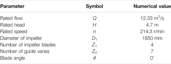
TABLE 1. The main geometric and performance parameters of the pump device.
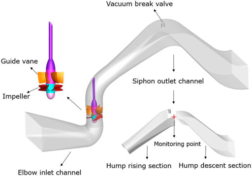
FIGURE 1. Calculation model.
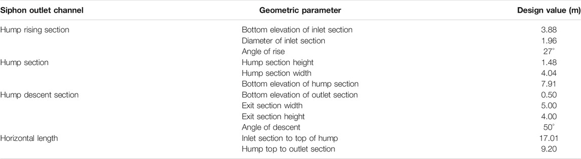
TABLE 2. Main geometric parameters of siphon outflow channel.
Numerical Method
Governing Equation
In this paper, the numerical simulation of the pump device is carried out based on the VOF two-phase flow model, and the free surface is characterized by volume function to track the change of gas-liquid two-phase conversion. The flow inside the pump device is regarded as three-dimensional incompressible non-viscous turbulence. The control equation of numerical calculation is as (Shi et al., 2017; Chen et al., 2018; Kan et al., 2019):
Continuity equation:
Momentum equation:
where
In the grid control volume, the expression of phase-separated material property parameters is as follows (Karim et al., 2014; Zhou et al., 2019):
where
Turbulent Flow Model
In this paper, three turbulence models of
The calculation errors of different turbulence models are shown in Table 3. The error of the
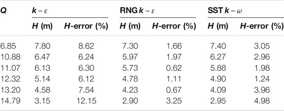
TABLE 3. Calculation errors of different turbulence models.
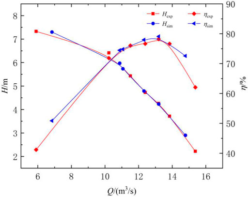
FIGURE 2. Comparison of pump head and efficiency curve between numerical calculation and experiment.
Among them:
where
Calculation Model and Boundary Conditions
In this paper, the numerical calculation of keeping the vacuum breaking valve closed is defined as Case 1, and the numerical calculation of pre-opening the vacuum breaking valve is defined as Case 2. The start-up and exhaust process of axial flow pump unit involves air and water. It is necessary to set a certain height of the air domain above the inlet and outlet pools. The water level height of inlet and outlet pool is consistent with the upstream and downstream water level of pumping station design. According to the water level of the upstream and downstream reservoirs, the initial conditions of the integral number of gas and liquid in each part of the pump device are given. According to the water depth of the upstream and downstream reservoirs, the hydrostatic pressure distribution at the inlet and outlet as shown in Supplementary Figure 3 is given. The top of the air domain is set as an open outlet, and the pressure gradient is 0. The entire calculation domain adopts the no-slip assumption, and the flow in the calculation domain is a two-phase flow composed of a mixture of water and air. For upstream and downstream reservoirs, the calculation range includes blue and red areas. The blue region represents the volume of water, and the red region represents the volume of air. The water volume and air volume of the reservoir are tested independently. Considering the calculation amount, the water volume and air volume of the reservoir are determined as shown in Supplementary Figure 4.
Calculation Grids
In order to ensure the consistency of grid size, the calculation domain is divided into eight blocks by hexahedral structured grid. In order to ensure the accuracy of the numerical calculation results, the boundary layer encryption is performed on the grids at the edge walls of the convection channel, impeller and guide vane. In order to capture the two-phase exchange at the gas-liquid interface and the free surface more accurately, the grids near the outlet wall of the vacuum damage valve and the free surface of the inlet and outlet tank are refined. In the grid parameters, y+ (Ansys, 2013) represents the distance from the first grid node to the wall. The y + values in the calculation domain in this paper are all within 10 to ensure that the first layer of grid nodes are concentrated near the solid wall. This paper has prepared five sets of grid node schemes to study the influence of the number of grids on the numerical calculation results, as shown in Table 4. The results of mesh independence analysis show that when the mesh number is larger than 3.89 million, the performance parameters of the pump device are basically unchanged with the increase of the mesh number. On the basis of comprehensive consideration of calculation accuracy and computing resources, 4.96 million grid elements are selected for this numerical calculation. At the same time, in order to further ensure the credibility of the numerical calculation, the Richardson extrapolation theory of reference (Celik et al., 2008) is used to check the convergence of the selected grid based on GCI. The numerical uncertainty of the grid solution is 2.68%. The calculation grids is shown in Figure 3.
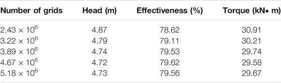
TABLE 4. Grid independence test.
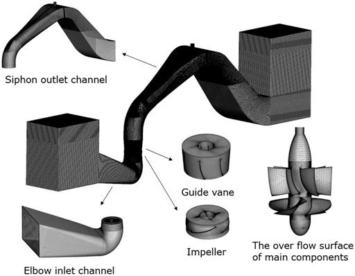
FIGURE 3. Calculation grids.
Numerical Scheme and Solution Method
The calculation of this number of times is performed based on CFD software. The flow control equation is discretized by the finite volume method based on the element center. The second-order upwind scheme is used for the discretization of the agreement term, and the first-order implicit scheme is used for the discretization of the turbulence term. Through the CEL function, the self-defined static pressure distribution of the reference water depth is used for the inlet and outlet boundary conditions, and the pressure distribution of the upstream and downstream water bodies varies with the water depth. The if statement is used to define the gas-liquid interface under the initial conditions. The flow chart of the If function is shown in Figure 4. The part of the pump system below the free surface of the inlet and outlet pools is the water body, the volume fraction of water is 100%, and the volume fraction of air is 0%. The part of the free surface of the pool is gas, the volume fraction of water is 0%, and the volume fraction of air is 100%. The flow chart of the initial conditions for the volume fraction of air and water is shown in Supplementary Figure 5. The volume fraction of each part of the calculation domain is initialized. According to the site data of the pump station, the step function is called to control the starting acceleration of the runner. According to the field data of the pump station, the step function is used to control the start-up acceleration of the runner. The acceleration process of the pump is linear acceleration and the acceleration process is 4 s. The acceleration process of the pump is updated in real time in the iterative calculation. The transient Frozen Rotor slip interface is selected to realize the numerical calculation of the transient process of pump start by using the multiple coordinate system algorithm. In this calculation, considering the calculation accuracy and calculation workload, the total calculation time is selected as 1,000 s, and the time step is set to 0.1 s. The upper iteration limit of each time step is set to 30 times, and the residual convergence benchmark of each time step is set to 10−5. In the numerical calculation of keeping the vacuum break valve closed, the outlet of the vacuum break valve is set to the solid wall. When the flow is filled with the rising section of the flow channel, the boundary condition of the open outlet is changed to the solid wall until the end of the numerical calculation. The numerical calculation was carried out in the Supercomputing Center of the Key Laboratory of Water Conservancy and Power Engineering of Yangzhou University. A total of five computing nodes are used, and each computing node has 32 cores. The calculation time for a single working condition is about 144 h.
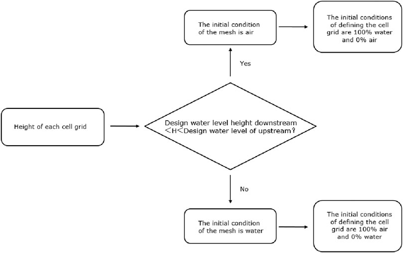
FIGURE 4. Flow chart of If function.
Result Analysis
Comparison Between Numerical Simulation and Experiment
In the early stage of this numerical calculation, transient calculation was carried out for the start-up and exhaust processes of the pump device under different upstream and downstream water levels. The comparison between the external characteristic parameters and the steady-state test results of the pump device exhaust is shown in Figure 5. It can be seen from Figure 5 that the external characteristic parameters of the pump device are consistent with the steady-state test values in the overall trend, and the difference is within ±5%. It shows that the use of the CFD numerical format in this paper for the transient calculation of the start-up exhaust process has certain validity and accuracy.
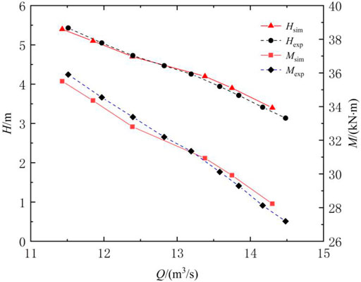
FIGURE 5. Comparison of test value and simulation value of head and torque.
Changes in External Characteristic Parameters
According to the changes of water level and pressure in the flow channel, the start-up transition process from start-up to stable operation is divided into four stages, as shown in Figure 6. The water flow over the hump from the start-up of the unit to the rising of the hump is defined as the hydraulic gas drive stage. The water level over the hump to the bottom of the hump is defined as the weir flow stage. The water level over the bottom of the hump to the top of the hump before exhausting is defined as the siphon formation stage. The air exhausting in the pump device and the formation of full pipe flow are defined as the stable operation stage.
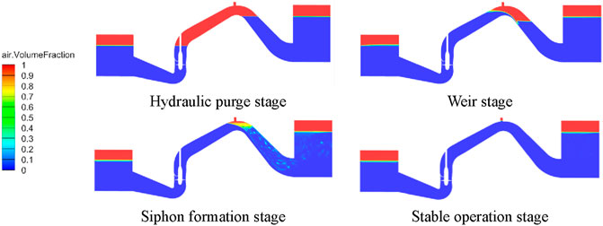
FIGURE 6. Stage division in the exhaust process.
Figure 7 shows the changes of pressure, torque, and axial force at the monitoring point at the top of the hump during the start of the pump device over time. After the pumping station unit is started up and running, the impeller speed increases linearly, the head and torque of the pump system gradually increase, and the pump reaches the rated speed in 4 s. As the exhaust process progresses, the bubbles in the flow channel are transported and collapsed, and the characteristic parameters of the pump device fluctuate to a certain extent. When the exhaust is gradually completed, the fluctuation range of the characteristic parameters decreases and tends to be stable.
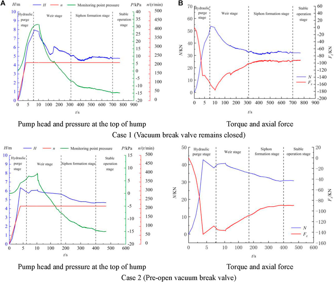
FIGURE 7. Time history curve of dynamic parameters of pump in exhaust process.
In Case 1, the starting head of the pump device reaches the maximum value in the hydraulic gas drive stage, and the transient impact head reaches 7.96 m, which is 1.69 times of the rated head. There is still a large fluctuation of head in weir flow stage and a secondary peak of head appears. As the water level rises, the water flow compresses the air, and the pressure value at the monitoring point at the top of the hump gradually rises from zero. When t = 10 s, the pump device is in the weir flow stage, and the maximum pressure at the top of the hump is 31.49 kPa. Subsequently, the pressure at the monitoring point continued to drop. When t = 225 s, a negative pressure appeared at the top of the hump. When t = 700 s, the pump device entered a stable operation stage. The exhaust process ended, and the pressure at the top of the hump was −14.67 kPa.
In case 2, the maximum starting head of the pump device also appeared in the hydraulic drive stage, and the instantaneous impact head reached 6.35 m, which was 1.35 times the rated head. Then the head gradually decreased, and the overall trend tended to be flat. The maximum pressure of the monitoring point at the top of the hump appears at t = 12 s, and the pump device is in the weir flow stage. At this time, the pressure at the top of the hump is 7.97 kPa, and then the pressure at the monitoring point continues to drop. When t = 64 s, the top of the hump When t = 400 s, the pump device enters a stable operation stage, and the pressure at the top of the hump is -14.66 kPa.
Compared with the characteristic parameters in the start-up process of case 1 and case 2, the fluctuation and oscillation phenomenon of characteristic parameters in case 1 is obviously stronger than that in case 2. The maximum starting head of Case 1 is 1.25 times that of Case 2, and the maximum pressure at the peak is 3.95 times that of Case 2. It indicates that there is a strong unstable flow phenomenon in Case 1 compared with Case 2. After the pump device enters the stable operation stage, the head, torque and negative pressure at the top of the hump in cases 1 and 2 are relatively close, and they are highly consistent with the experimental data under the rated working conditions of the pump station.
Internal Flow Field Evolution
In order to further study the transient characteristics of the internal flow field during the startup of the pump device, the instantaneous velocity streamline of the pump device at a typical time in the operation phase is selected, as shown in Figure 8.
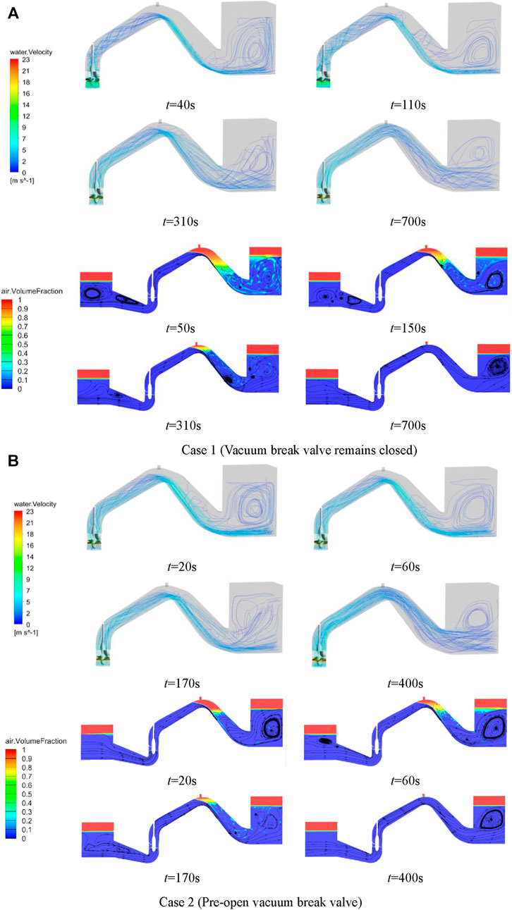
FIGURE 8. Instantaneous velocity streamlines.
In Case 1, after the start-up of the unit, the flow rate gradually increases, and the water level in the outlet channel rises. The flow pattern in the impeller channel is chaotic and complex, and the backflow and flow separation are serious. A large-scale time-varying vortex appears in the guide vane, blocking the flow passage in the impeller area, and hindering the inflow and outflow of water in the impeller channel. The water flows through the guide vane in a spiral shape, and the hump rising section is filled with spiral water. The flow field of the pump device is significantly affected by the instantaneous impact characteristics during the pump startup. As the exhaust process progresses, the small-scale vortex area of the inlet flow channel moves to the inlet of the inlet flow channel. The turbulence of the water flow in the impeller channel and the blocking of the flow channel by the time-varying vortex in the guide vane are improved. In the weir flow stage, water and air are mixed in the descending section of the outlet flow channel, and the water flow adheres to the wall to form a vortex with air-carrying and exhausting capabilities in the descending section of the hump. Due to the progress of the exhaust process in the outlet pool, the water flow has a relatively strong tumbling and swirling, and a large-scale backflow zone appears. When t = 310 s, the pump device is in the siphon formation stage, and there is still a certain scale of vortex in the inlet channel. The flow pattern in the impeller channel is disordered, and the phenomenon of time-varying vortex blocking through the flow channel in the guide vane disappears. The flow streamline in the rising section of the outlet channel is relatively smooth, and the spiral effluent is obviously improved. The vortex intensity with air-carrying and exhaust capacity in the descending section of outflow channel decreases, and the exhaust capacity decreases. The phenomenon of water flow rolling and gyration caused by exhaust in the outlet pool is weakened, and the range of large-scale recirculation zone is reduced. When t = 700 s, the pump device enters the stable operation stage. The vortex area in the inlet passage disappears, the flow line in the rising section of the outlet passage is smooth, and the spiral effluent disappears. The vortex-carrying area in the descending section of the outflow channel disappeared. The phenomenon of flow rolling and gyrating in the outlet pool disappeared, and the backflow phenomenon further weakened. The pump enters a stable operation state.
Compared with Case 1, the internal flow field of Case 2 is relatively stable at different stages. The streamline in the inlet is smooth without obvious vortex and backflow. There is no obvious backflow and flow separation in the impeller channel. The flow in the guide vane channel is unobstructed, and the phenomenon of time-varying vortex blocking through the flow channel disappears. The water flow through the guide vane is obviously weakened, and the flow field of the pump device is significantly less affected by the instantaneous impact characteristics during the pump startup. The evolution law of internal flow field in Case 2 is close to that in Case 1. Affected by the exhaust velocity, the evolution of internal flow field in Case 1 has obvious hysteresis in time.
The flow chart of the Schematic diagram of the position of the mid-span section is shown in Supplementary Figure 6. Figure 9 shows the streamline distribution at different stages of medium-span section. In the stage of hydraulic drive, the phenomenon of flow separation and vortex appeared in the pump section, and the flow separation was obvious at the guide vane. After the pump device entered the weir flow stage, the unstable flow phenomenon in the pump section was more intense. The large-scale vortex on the back of the guide vane blocked the flow channel. With the exhaust process, the unstable flow phenomenon in the pump section disappeared, and the vortex scale at the guide vane decreased gradually. When the exhaust process is completed, the phenomenon of vortex blocking through the flow passage in the guide vane region disappears. The flow line of medium-span water flow in the pump section is smooth and straight without vortex backflow. Compared with Case 1, the vortex scale in the guide vane area of Case 2 is small at different stages, and the phenomenon of vortex blocking through the flow channel is weak. The internal flow field of the pump device during the start-up transition is relatively stable.
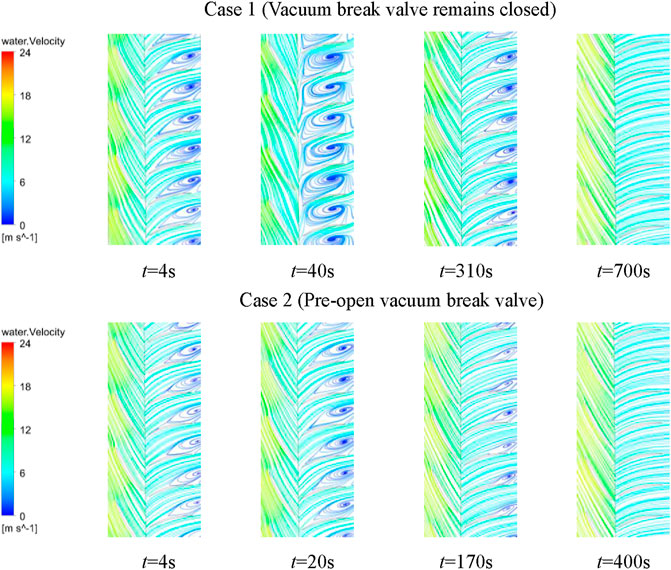
FIGURE 9. Velocity streamlines of cross-sectional span at different moments.
Entropy Generation Characteristics of the Impeller Zone
In order to analyze the energy dissipation of the pump device during the start-up transition, the entropy production rate (EPR) distribution of the mid-span section at different times is analyzed. It can be seen from Figure 10 that the high-entropy zone of the impeller zone in the weir flow stage is the largest, and the entropy value is significantly higher than that of other stages. At this stage, the unstable flow phenomenon in the impeller zone leads to serious energy dissipation. With the exhaust process, the unstable flow phenomenon in the impeller area gradually disappears, and the range of high entropy production area in the impeller area gradually narrows. After the exhaust of the pump device enters the stable operation stage, the high entropy production area of the impeller area basically disappears. Compared with Case 1, the range of high entropy production area of pump device in Case 2 is small at different stages, and the high entropy production area and entropy value of mid-span section in weir flow stage are significantly reduced. The dissipation of high entropy production area in Case 1 has obvious hysteresis in time.
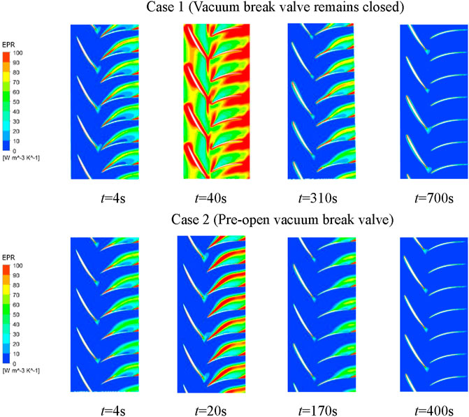
FIGURE 10. Distribution of entropy production rate of mid-span section at different times.
Combined with the flow line analysis of the mid-span section in the previous section, it can be seen that the phenomenon of flow shedding and vortex blocking across the flow channel at the guide vane in the weir flow stage is the most obvious. With the exhaust process, the unstable flow phenomenon gradually weakens and disappears, and the flow pattern in the impeller area tends to be stable. The strong unstable flow phenomenon in the impeller area causes large energy dissipation. This is consistent with the evolution law of entropy distribution.
Pressure Distribution of Impeller Blades
In this paper, the static pressure distribution of the impeller blade surface in different exhaust stages during startup is selected. The left side is the suction surface and the right side is the pressure surface, as shown in Figure 11. In Case 1, after the start-up of the unit, the impeller rotates and accelerates. At the beginning of the impeller acceleration, the static pressure distribution of the impeller suction surface and the pressure surface is basically the same, and the pressure difference is small. When t = 4 s, the pressure difference between the suction surface and the pressure of the impeller increases significantly. Due to the acceleration of the fluid, a small range of low pressure zone appears in the leading edge of the suction surface. The leading edge of the pressure surface is affected by the impact of water flow, and a small high pressure zone appears. With the rise of the water level in the channel, when the pump device enters the weir flow stage, the pressure on the blade surface increases further. There is a significant high pressure zone at the edge of the impeller pressure surface, and the pressure can reach 140 kPa. The pressure distribution on the suction surface is not uniform, and the area of the front low pressure zone on the inlet side of the suction surface expands. When the pump device enters the siphon formation stage, the pressure at the top of the hump gradually becomes negative. The pressure of the impeller is weakened by the influence of bubble transfer and collapse. The pressure on the blade surface gradually decreases, and the pressure distribution tends to be stable. There is no significant high pressure area and low pressure area.
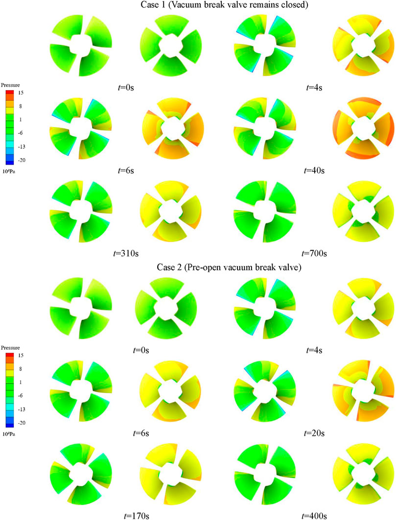
FIGURE 11. Static pressure contour of impeller blade surface at different time.
The evolution of pressure distribution on blade surface in case 2 is similar to that in case 1. Compared with Case 1, the influence of the instantaneous impact of impeller acceleration on the blade is significantly weaker. In different stages of the startup process, the blade surface pressure distribution of case 2 is more uniform. The maximum pressure on the blade surface is obviously lower, and the range of high pressure zone and low pressure zone on the blade surface is obviously smaller.
Time Characteristics of the Exhaust Process
Figure 12 shows the evolution of water-air interface in the flow channel during exhaust. In Case 1, after the unit was started, the water level in the ascending section of the outlet channel gradually increased. Due to the closure of the vacuum damage valve, the air in the channel was squeezed by the flow in the ascending section, and gradually moved to the descending section of the outlet channel. The water level in the descending section decreased with the passage and extrusion of the air in the channel. When t = 7.6 s, the upwelling flow over the hump. Pump device enters weir flow stage. Weir flow is formed by water adhering to the wall, and the mixing of water and gas is intense in the descending section of the outlet channel. In the descending section of the hump near the exit, a large number of bubbles are carried into and out of the pool with the flow rolling. Bubbles in the pond roll out and the water surface in the pond has obvious shaking. When t = 310 s, the water level in the descending section of the hump overtook the bottom of the hump. The pump device enters the siphon formation stage. At this time, the top of the hump has formed a negative pressure state, and there is only a thin layer of air mass at the top of the hump. With the slow release of gas-liquid mixing, the phenomenon of water-gas rolling in the descending section of outflow channel disappears. The carrying capacity of water flow is obviously reduced. The number of bubbles in the outlet pool was significantly reduced, and the water surface in the outlet pool was stable without obvious fluctuation. When t = 700 s, the air in the pump is completely discharged. Full pipe flow is formed in the outflow channel. The pump device enters the stable operation stage.
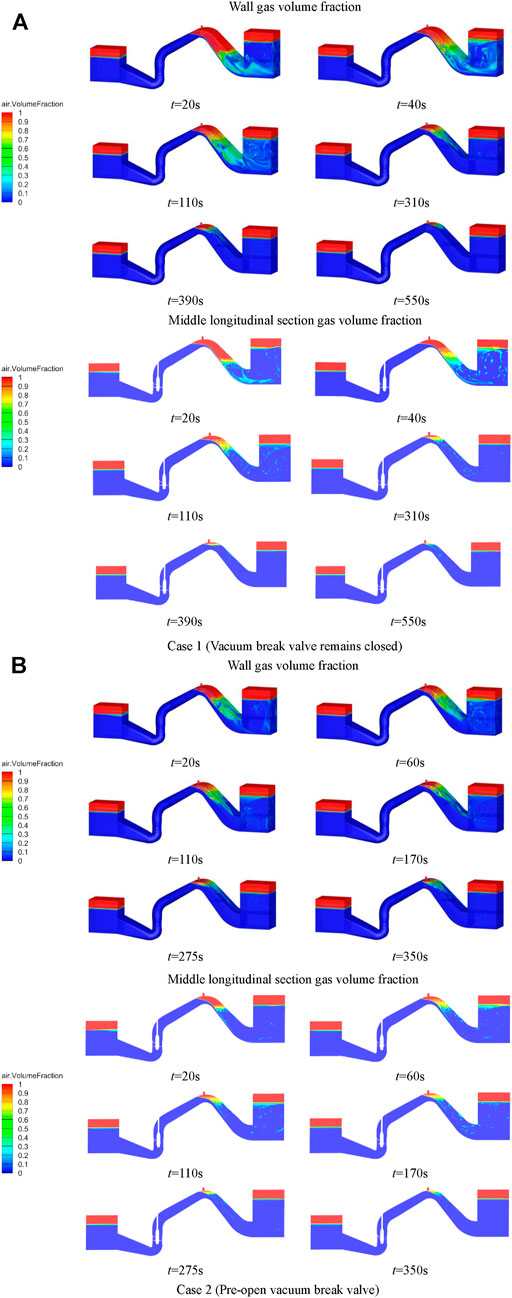
FIGURE 12. Evolution of the water-gas interface.
Compared with Case 1, when the unit starts in Case 2, the vacuum damage valve is opened in advance. The air in the channel is squeezed by the flow in the hump rising section and flows out of the vacuum damage valve. The water flow in the descending section was not squeezed by the air in the channel. The water level in the pond remains basically unchanged. When t = 6.2 s, the flow over the hump, vacuum damage valve closed. Pump device enters weir flow stage. Different from Case 1, in the weir flow stage of Case 2, the exhaust was stable in the hump descent stage. Water and gas mixing degree is low. The phenomenon of bubbles rolling around with water disappears. The fluctuation of water surface in the outlet pool is small, and the bubble rolling phenomenon in the pool disappears. Compared with Case 1, the exhaust time in each stage of Case 2 is significantly shortened. The hydraulic gas drive stage takes 6.2 s, which is shortened by 18.4%. Weir flow stage takes 163.8 s, shortened by 45.83%. The siphon formation stage took 230 s, which was shortened by 41.03%. The total duration from start-up to stable operation is 400 s, which is reduced by 42.86%.
Select the typical cross section shown in Figure 13 to further analyze the bubble transport process in the flow channel. Figure 14 is the distribution of gas volume fraction in weir flow and siphon formation stages. It can be seen from Figure 12 that the mixing of water and gas is severe in the weir flow stage. The gas distribution in each section of the hump descent section is wide, and the gas diving depth is deep. The phenomenon of water and gas mixing is weak in the siphon formation stage. The gas proportion of each section in the hump descending section is relatively small. The air mass is concentrated in the upper and middle parts of the section, and the air mass at the bottom of the section is less. There is no obvious law of gas volume distribution in each section during the exhaust process. In the siphon formation stage, the air mass with a certain volume proportion still moves and discharges in each section of the hump descent section. Compared with case 1, case 2 pump device water gas mixing phenomenon is weak. The gas volume of each section in the hump descending section is relatively small.
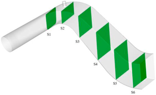
FIGURE 13. Schematic diagram of section position.
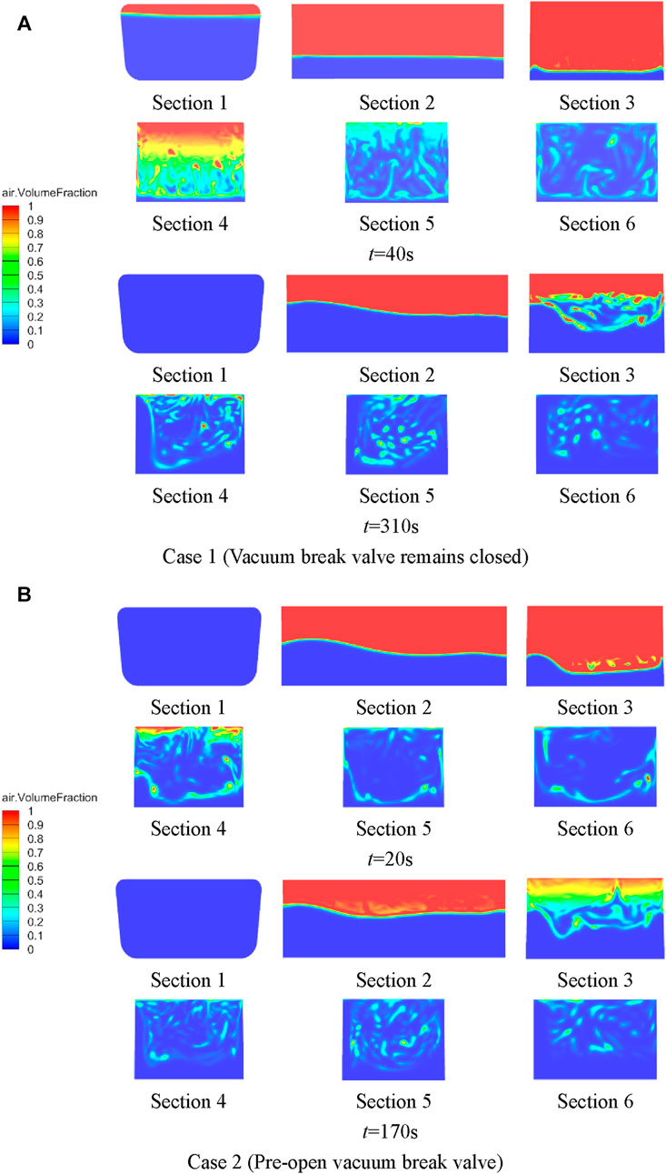
FIGURE 14. Water vapor evolution of typical cross section.
The gas volume in the outlet channel is monitored and the monitoring data is processed. The average exhaust rate is introduced to approximately represent the average exhaust rate in a period of time, the expression is:
where is the time spent in each exhaust stage, and is the volume of gas discharged in each stage The gas volume fraction in outlet channel is shown in Figure 15. The time characteristics of the exhaust process is shown in Table 5.
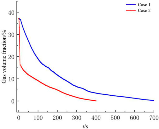
FIGURE 15. Gas volume fraction in outlet channel.
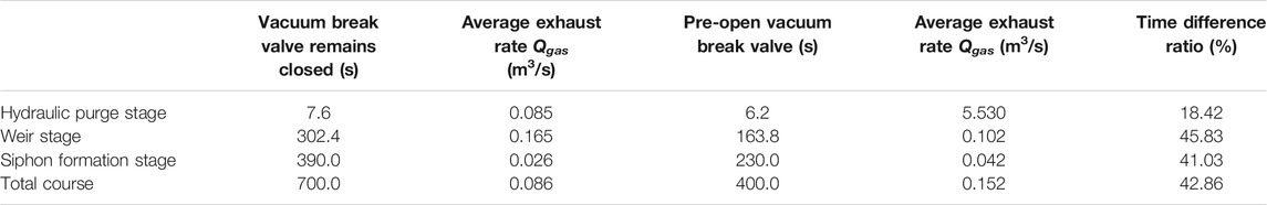
TABLE 5. Time characteristics of the exhaust process.
Due to the vacuum failure valve in case 1 remained closed, the gas volume fraction in the flow channel remained basically unchanged by about 37%. When the pump device enters the weir flow stage, the gas volume fraction of the pump device begins to decrease. The decline trend of gas volume fraction in the early stage of this stage remained stable. When the water level rises gradually, the slope of the gas volume fraction curve decreases with time, and the exhaust rate decreases gradually. The average exhaust rate in the weir flow stage is 0.165 m3/s.
When t = 310 s, the pump device enters the siphon formation stage. At this time, the gas volume fraction in the flow channel is only 6.11%. Since the slope of the gas volume fraction curve decreases sharply with time and further decreases, the average exhaust rate is 0.158 times that of the weir flow stage. The exhaust rate at siphon formation stage is about 0.026 m3/s. This stage takes the longest time in the exhaust process.
Compared with case 1, case 2 pre-opens the vacuum damage valve. The gas volume fraction in the hydraulic drive stage decreases rapidly. The exhaust rate is fast and maintains a stable value. The average exhaust rate in the hydraulic drive stage is 5.53 mm3/s. When t = 6.2 s, the flow over the hump, vacuum damage valve closed, the gas volume fraction of 26.34%. The air in the flow channel cannot flow out from the vacuum damage valve, and gradually moves to the descending section of the outflow channel. When t = 11 s, water and gas are mixed in the descending section of hump. The gas in the channel continues to escape through the outlet pool, and the gas volume fraction continues to decline. When t = 170 s, the pump device enters the siphon formation stage. The average exhaust rate at this stage is 0.042 m3/s. Compared with Case 1, the exhaust rate of Case 2 is significantly faster.
Conclusion
In order to explore the transient characteristics of the start-up and exhaust process of the vertical siphon axial flow pump unit, this paper conducts a numerical simulation study on the whole system of the pumping station. The transient characteristics and the time characteristics of siphon formation in the transition process of the pump device are predicted. The differences in the flow field evolution between the pre-opening valve startup and the closing valve startup were compared in detail. The main conclusions are as follows:
1) There is a serious instability in the internal flow field of the pump device where the vacuum failure valve is kept closed. The blade surface bears strong instantaneous impact. The flow field of the pump device that pre-opens the vacuum damage valve is significantly less affected by the instantaneous impact characteristics during the pump startup. The range of high entropy production area in impeller channel is small. The duration of high entropy production area is significantly shortened. The instantaneous impact on the blade surface is weak.
2) There is a similarity in the evolution law of the internal flow field in the pump device where the vacuum failure valve is kept closed and pre-opened. In the exhaust process, the unsteady flow in weir flow stage is the most significant. The maximum instantaneous impact on the blade surface also occurs mainly in the weir flow stage. The very few remaining gas in the siphon formation stage is difficult to discharge and takes a long time.
3) The external characteristic parameters of the pump device under the two starting modes are in good agreement with the test results. Compared with the start-up mode of vacuum damage valve keeping closed, the maximum start-up head is reduced by 17% and the exhaust time is shortened by 45% by pre-opening the vacuum damage valve. The pre-open vacuum breaking valve effectively avoids the system instability caused by the start-up and exhaust of the pump device.
Data Availability Statement
The original contributions presented in the study are included in the article/Supplementary Material, further inquiries can be directed to the corresponding author.
Author Contributions
Author Contributions: XZ contributed with data curation, formal analysis and writing original draft preparation; FT contributed with visualization and writing review and editing the paper; and HL and WH carried out the experiments validation. All authors have read and agreed to the published version of the manuscript.
Funding
This research work was supported by the National Natural Science Foundation of China (Grant No. 51376155), the Natural Science Foundation of Jiangsu Province (Grant No. BK20190914), the China Postdoctoral Science Foundation (Grant No. 2019M661946), and the University Science Research Project of Jiangsu Province (Grant No. 19KJB570002). A project funded by the Priority Academic Program Development (PAPD) of Jiangsu Higher Education Institutions Support for construction and assembly of the facility was also provided by the Hydrodynamic Engineering Laboratory of Jiangsu Province.
Conflict of Interest
The authors declare that the research was conducted in the absence of any commercial or financial relationships that could be construed as a potential conflict of interest.
Supplementary Material
The Supplementary Material for this article can be found online at: https://www.frontiersin.org/articles/10.3389/fenrg.2021.706975/full#supplementary-material
Abbreviations
3-D, Three-dimensional; CFD, Computational fluid dynamics; SST, Shear-stress transport; VOF, Volume of fluids; F, Equivalent volume force form of surface tension; Fz, Axial force of impeller (N); g, Local acceleration of gravity (m/s2); k, Turbulent kinetic energy; Hexp, Experimental head (m); M, The impeller torque (kN·m); n, Rated speed (r/min); N, Rotation speed (r/min); P, The instantaneous pressure (kPa); Q, Flow rate of the model pump device (m3/s); Qgas, Average exhaust rate; t, Time (s); u, Velocity (m/s); v, Average exhaust rate(m3/s);
References
Ahn, S.-H., Xiao, Y., Wang, Z., Zhou, X., and Luo, Y. (2017). Numerical Prediction on the Effect of Free Surface Vortex on Intake Flow Characteristics for Tidal Power Station. Renew. Energ. 101, 617–628. doi:10.1016/j.renene.2016.09.021
Aydin, M. C., Öztürk, M., and Yücel, A. (2015). Experimental and Numerical Investigation of Self-Priming Siphon Side Weir on a Straight Open Channel. Flow Meas. Instrumentation 45, 140–150. doi:10.1016/j.flowmeasinst.2015.06.014
Celik, I. B., Ghia, U., Roache, P. J., and Freitas, C. J. (2008). Procedure for Estimation and Reporting of Uncertainty Due to Discretization in CFD Applications. J. Fluids Eng. 130 (7), 078001. doi:10.1115/1.2960953
Chen, H., Zhou, D., Zheng, Y., Jiang, S., Yu, A., and Guo, Y. (2018). Load Rejection Transient Process Simulation of a Kaplan Turbine Model by Co-adjusting Guide Vanes and Runner Blades. Energ. 11 (12), 3354. doi:10.3390/en11123354
Fu, S., Zheng, Y., Kan, K., Chen, H., Han, X., Liang, X., et al. (2020). Numerical Simulation and Experimental Study of Transient Characteristics in an Axial Flow Pump during Start-Up. Renew. Energ. 146, 1879–1887. doi:10.1016/j.renene.2019.07.123
Hu, F. F., Ma, X. D., Wu, D. Z., and Wang, L. Q. (2012). Transient Internal Characteristic Study of a Centrifugal Pump during Startup Process. IOP Conf. Ser. Earth Environ. Sci. IOP Publishing 15 (4), 042016. doi:10.1088/1755-1315/15/4/042016
Intriago Zambrano, J. C., Michavila, J., Arenas Pinilla, E., Diehl, J. C., and Ertsen, M. W. (2019). Water Lifting Water: a Comprehensive Spatiotemporal Review on the Hydro-Powered Water Pumping Technologies. Water 11 (8), 1677. doi:10.3390/w11081677
Jintao, L., Shuhong, L., Yuekun, S., Yulin, W., and Leqin, W. (2013). Three Dimensional Flow Simulation of Load Rejection of a Prototype Pump-Turbine. Eng. Comput. 29 (4), 417–426. doi:10.1007/s00366-012-0258-x
Kan, K., Chen, H., Zheng, Y., Zhou, D., Binama, M., and Dai, J. (2021). Transient Characteristics during Power-Off Process in a Shaft Extension Tubular Pump by Using a Suitable Numerical Model. Renew. Energ. 164, 109–121. doi:10.1016/j.renene.2020.09.001
Kan, K., Zheng, Y., Chen, H., Cheng, J., Gao, J., and Yang, C. (2019). Study into the Improvement of Dynamic Stress Characteristics and Prototype Test of an Impeller Blade of an Axial-Flow Pump Based on Bidirectional Fluid-Structure Interaction. Appl. Sci. 9 (17), 3601. doi:10.3390/app9173601
Karim, M. M., Prasad, B., and Rahman, N. (2014). Numerical Simulation of Free Surface Water Wave for the Flow Around NACA 0015 Hydrofoil Using the Volume of Fluid (VOF) Method. Ocean Eng. 78, 89–94. doi:10.1016/j.oceaneng.2013.12.013
Lefebvre, P. J., and Barker, W. P. (1995). Centrifugal Pump Performance during Transient Operation. J. Fluid Eng-t Asme 117 (1), 123–128. doi:10.1115/1.2816801
Li, W., Ji, L., Shi, W., Zhou, L., Jiang, X., and Zhang, Y. (2018). Fluid-structure Interaction Study of a Mixed-Flow Pump Impeller during Startup. Eng. computations 35, 18–34. doi:10.1108/ec-01-2016-0043
Li, X., Tang, X., Zhu, M., and Shi, X. (2019). 1D-3D Coupling Investigation of Hydraulic Transient for Power-Supply Failure of Centrifugal Pump-Pipe System. J. Hydroinformatics 21 (5), 708–726. doi:10.2166/hydro.2019.122
Li, Z., Wu, P., Wu, D., and Wang, L. (2011). Experimental and Numerical Study of Transient Flow in a Centrifugal Pump during Startup. J. Mech. Sci. Technol. 25 (3), 749–757. doi:10.1007/s12206-011-0107-7
Liu, J., Li, Z., Wang, L., and Jiao, L. (2011). Numerical Simulation of the Transient Flow in a Radial Flow Pump during Stopping Period. J. Fluids Eng. 133 (11), 111101. doi:10.1115/1.4005137
Minato, A., Nagahara, T., and Nakajima, N. (2006). Simulation des écoulements diphasiques dans les stations de pompage. La Houille Blanche 92 (1), 59–64. doi:10.1051/lhb:200601007
Shi, L., Tang, F., Xie, R., and Zhang, W. (2017). Numerical and Experimental Investigation of Tank-type Axial-Flow Pump Device. Adv. Mech. Eng. 9 (3), 1687814017695681. doi:10.1177/1687814017695681
Shi, W., Zhang, D., Guan, X., and Leng, H. (2010). Numerical and Experimental Investigation of High-Efficiency Axial-Flow Pump. Chin. J. Mech. Eng-Eng Ed 23 (1), 42–48. doi:10.3901/cjme.2010.01.038
Tsukamoto, H., and Ohashi, H. (1982). Transient Characteristics of a Centrifugal Pump during Starting Period. J. Fluid Eng-t Asme 104 (1), 6–13. doi:10.1115/1.3240859
Wang, Z., Peng, G., Zhou, L., and Hu, D. (2010). Hydraulic Performance of a Large Slanted Axial‐flow Pump. Eng. computations 27 (2), 243–256. doi:10.1108/02644401011022391
Wu, D., Wu, P., Li, Z., and Wang, L. (2010). The Transient Flow in a Centrifugal Pump during the Discharge Valve Rapid Opening Process. Nucl. Eng. Des. 240 (12), 4061–4068. doi:10.1016/j.nucengdes.2010.08.024
Xie, C., Tang, F., Zhang, R., Zhou, W., Zhang, W., and Yang, F. (2018). Numerical Calculation of Axial-Flow Pump’s Pressure Fluctuation and Model Test Analysis. Adv. Mech. Eng. 10 (4), 1687814018769775. doi:10.1177/1687814018769775
Yang, Z., Cheng, Y., Xia, L., Meng, W., Liu, K., and Zhang, X. (2020). Evolutions of Flow Patterns and Pressure Fluctuations in a Prototype Pump-Turbine during the Runaway Transient Process after Pump-Trip. Renew. Energ. 152, 1149–1159. doi:10.1016/j.renene.2020.01.079
Zhan, J.-m., Wang, B.-c., Yu, L.-h., Li, Y.-s., and Tang, L. (2012). Numerical Investigation of Flow Patterns in Different Pump Intake Systems. J. Hydrodyn 24 (6), 873–882. doi:10.1016/s1001-6058(11)60315-6
Zhang, X., Cheng, Y., Yang, Z., Chen, Q., and Liu, D. (2021). Water Column Separation in Pump-Turbine after Load Rejection: 1D-3D Coupled Simulation of a Model Pumped-Storage System. Renew. Energ. 163, 685–697. doi:10.1016/j.renene.2020.08.163
Zhang, Y.-L., Zhu, Z.-C., Zhao, Y.-J., Wu, J., and Zhou, F.-L. (2020). Comparative Experiments on a Self-Priming Pump Delivering Water Medium during Rapid and Slow Starting Periods. Iranian J. Sci. Technol. Trans. Mech. Eng., 1–13.
Zhou, B., Yuan, J., Lu, J., and Hong, F. (2017). Investigation on Transient Behavior of Residual Heat Removal Pumps in 1000 MW Nuclear Power Plant Using a 1D-3D Coupling Methodology during Start-Up Period. Ann. Nucl. Energ. 110, 560–569. doi:10.1016/j.anucene.2017.07.013
Keywords: pumping station, start-up process, transient characteristics, gas-liquid two-phase flow, three-dimensional numerical simulation, siphon outlet channel
Citation: Zhang X, Tang F, Liu C, Shi L, Liu H, Sun Z and Hu W (2021) Numerical Simulation of Transient Characteristics of Start-Up Transition Process of Large Vertical Siphon Axial Flow Pump Station. Front. Energy Res. 9:706975. doi: 10.3389/fenrg.2021.706975
Received: 08 May 2021; Accepted: 30 June 2021;
Published: 19 July 2021.
Edited by:
Enhua Wang, Beijing Institute of Technology, ChinaReviewed by:
Bin Xu, Clemson University, United StatesXiaoya Li, University of Science and Technology of China, China
Wang Zhiqi, Xiangtan University, China
Copyright © 2021 Zhang, Tang, Liu, Shi, Liu, Sun and Hu. This is an open-access article distributed under the terms of the Creative Commons Attribution License (CC BY). The use, distribution or reproduction in other forums is permitted, provided the original author(s) and the copyright owner(s) are credited and that the original publication in this journal is cited, in accordance with accepted academic practice. No use, distribution or reproduction is permitted which does not comply with these terms.
*Correspondence: Fangping Tang, tangfp@yzu.edu.cn