Potential Feature of Combined AB5-Type Metal Hydride Tank and PEMFC as a Safer System for Hydrogen Fueling in Bangladesh
 Md Abdus Salam
 Thauhidul Islam2
  Kawsar Ahmed
 Bawadi Abdullah
- 1Institute of Mining, Mineralogy and Metallurgy (IMMM), BCSIR, Dhaka, Bangladesh
- 2Hydrogen Energy Laboratory, Chattogram Laboratories, BCSIR, Dhaka, Bangladesh
- 3Chemical Engineering Department, Universiti Teknologi PETRONAS, Tronoh, Malaysia
Metal hydrides are very much reported as a potential safe option for high-density hydrogen storage materials. A combined system of proton-exchange membrane hydrogen fuel cell (PEMFC) and metal hydride (MH) tanks is designed to investigate their characteristics and performances as hydrogen storage and stable power supply system. An AB5-type (LaCe)Ni5 material containing three MH tanks is selected for investigation. Endothermic dehydrogenation of metal hydride controls the hydrogen evolution rates during a discharging period, which reduces the risk of accidents. The MH tank charged at a 20°C water bath sustains and supplies hydrogen for a longer time of 240 min. The performances of the MH tank at a water bath of 20°C and 10-bar conditions correspond to the optimum condition of hydrogen storage at the MH tank of Pragma Industries. The performances of the combined system were investigated in different working conditions. The system sustains and supplies hydrogen to PEMFC for 240, 160, 130, and 110 min for the working loads of 250, 500, 1,000, and 2,000 W, accordingly. It is concluded that hydrogen consumption frequency increases for higher load demand.
1 Introduction
Bangladesh, like many other countries, is currently focusing on hydrogen energy as an option. Most energy demand is met by natural gas in Bangladesh (about 70%). Other important sources of energy supply are oil, coal, biomass, and so on. To satisfy the rising demand, LNG and LPG are imported from different countries, as well as electricity. The use of renewable energy, instead of gas, coal, and oil, was initiated around the world and is critical for sustainable development and environmental protection by avoiding carbon emissions, to decrease the dependence on fossil fuels (Energypedia, 2017). Bangladesh produces a large amount of biomass due to its massive agricultural operations and high population density; hydrogen fuel is a very attractive choice for speeding up the paradigm shift to green energy. Biomass combines the attributes of gasoline with those of a renewable energy source. Biomass is the primary source of energy for cooking and heating in Bangladesh, particularly in rural regions. However, all of the biomass produced is not being used to its full potential, and solving this issue may help us address our energy and fuel crises with current technologies (Salam et al., 2018). Moreover, Bangladesh is a riverine country and very close to the Bay of Bengal. It has an enormous amount of water that can be a promising source of fuel if the electrolysis or water splitting process could be economic. Bangladesh has set up a milestone infrastructure to introduce and to demonstrate that hydrogen could be an alternative fuel.
Among all the alternatives, hydrogen appears to be the most promising in terms of reducing greenhouse gas (GHG) emissions, ensuring energy security and reducing local air pollution. Hydrogen has a much higher energy density per unit mass (34 kcal/g) than conventional fossil fuels (4–10 kcal/g), making it an energy-efficient fuel (Jain, 2009). A kilogram of hydrogen powers a fuel cell automobile for 100–131 km, whereas a kilogram of gasoline powers a typical car for 16 km. The increased interest in hydrogen, particularly for transportation applications, is due to the developments in fuel cell technology in the late 1990s and the utilization of hydrogen in the internal combustion engines without requiring substantial investments. Hydrogen is emission-free at the point of final use, avoiding both CO2 and air pollution emissions caused by transportation. Fuel cells, with their high conversion efficiencies relative to internal combustion engines, can also have a significant impact in this area (Sobrino et al., 2010).
Recent literature (Midilli et al., 2005; Balat, 2008; Veziroğlu, 2008; Barbir, 2009; Holladay et al., 2009; Jain, 2009; Zeng and Zhang, 2010) focuses on hydrogen applications in all spheres of human activity, including industrial, transportation, residential, and space. The use of hydrogen is primarily for oil refineries (Barreto et al., 2003; Muellerlanger et al., 2007); the production of ammonia/fertilizers (Ramachandran and K Menon, 1998; Lattin and Utgikar, 2007); and, to a smaller degree, the production of metals such as nickel, tungsten, molybdenum, copper, zinc, uranium, and plumage and consumes up to over 60 million tons (Richards and Shenoy, 2007; Krause et al., 2013) worldwide. In almost all applications, where fossil fuels are currently used and especially in car engines, hydrogen can be used as a fuel, offering immediate advantages in terms of reduced environmental contamination and cleaner environments (Eliezer et al., 2000; Barbir, 2009; Li et al., 2014).
Despite all the benefits of hydrogen as alternative energy, the storage of hydrogen remains an issue, because it is a highly flammable gas, making it dangerous to transport under high pressure in vehicles. A low pressure, but large-capacity, storage system provides a safer means of transporting hydrogen. Metal hydride, metal-organic frameworks (MOFs), nanotubes, intermetallic compound, graphene, and complex hydride are hydrogen storage materials. However, these storage materials are in an investigation level and are yet to be tested in larger prototypes. AB5-type metal hydride (MH) tanks are worthy of integrated investigation.
The most unique features of an AB5-type metal hydride crystalline compound are its accommodation of many substituting elements in large amounts into different active sites of the alloy, and the structure can be modified as required for properties such as thermodynamics, kinetics, recyclability, heat transfer, thermal defusibility, thermal stability, and microstructure. The materials can adsorb large quantities of reversible hydrogen, which is most important for stationary hydrogen tanks, gas separation, or refuelling. Moreover, the thermodynamics properties of the materials can be adjusted due to the large substitution of elements. Magnetic properties of AB5-type materials are favorable to hydrogen sorption.
The metal hydride storing system may offer an alternative to standard storage systems such as high-pressure, liquid, or cryogenic. More hydrogen per unit of volume (120 kg m−3) may be stored by solid compounds than liquid (70 kg m−3) and greater safety make the product an attractive solution. The most appropriate chemicals are called AB5 intermetallic compounds (A and B being elements with high and low affinity with hydrogen, respectively). The mechanism is shown in Equation (1).
(LaCe)Ni5 is one of the materials of the AB5-type metal hydride. The molecular hydrogen is dissociated at the surface and is interspersed during absorption into the metal matrix. As a result, hydrogen atoms are found on the LaNi metal lattice’s interstitial sites (Schlapbach and Züttel, 2001). The ability of LaNi5 to swiftly absorb and desorb hydrogen within the necessary temperature, pressure, and hysteresis allowing a good life cycle is very intriguing (Westerwaal and Haije, 2008; Hsieh et al., 2017a). Furthermore, it can store hydrogen at very low pressure, making it an ideal option for transportable applications where high-pressure systems are both unsafe and costly. The mass density of hydrogen in LaNi5H6 is only 2%, implying that La and Ni make up the great bulk of the system. This is insufficient for mobile applications, which require 4%–5% mass (the US DOE’s goals are 6.5% mass and 62 kg H2 m−3) (Westerwaal and Haije, 2008).
However, to generate electricity from the hydrogen gas of the MH tank, a proton-exchange membrane hydrogen fuel cell (PEMFC) is required. PEMFCs have a high power density, a fast start-up time, a quick reaction to changing loads, and a low operating temperature (Hsieh et al., 2017a). PEM fuel cells are widely acknowledged as a potential contender for power production in automotive, distributed power generation, and portable electronic applications. Despite extensive studies across the world, the cost of a fuel cell device is still too high to be commercially built (Wang, 2003). PEMFCs have several benefits, including a low operating temperature, continuous operation at a high current density, low weight, compactness, the possibility for cheap cost and volume, extended stack life, quick start-ups, and appropriateness for discontinuous operation (Barbir and Gomez, 1996; Chalk et al., 2000; Costamagna and Srinivasan, 2001a; Costamagna and Srinivasan, 2001b; Cacciola et al., 2001; Chu et al., 2001; Faur Ghenciu, 2002; Gamburzev and Appleby, 2002; Mehta and Cooper, 2003). PEMFCs are the most promising and appealing choice for a wide range of power applications, from portable/micropower and transportation to large-scale stationary power systems for buildings and distributed generation, thanks to their characteristics. Several companies have announced various applications, new technologies, and on-road prototype vehicles, including fuel pulse systems (Ballard, UTC, Nuvera, GE-FCS, Plug Power, Intelligent Energy, NovArs, Smart Fuel Cell, Toshiba, Sanyo, and Hydrogenics) and auto motors (Daimler-Chrysler, Ford, Renault, Toyota, Nissan, GM, BMW, and Hyundai). Furthermore, numerous technologies that use PEMFC for various applications are presently under development (Acres et al., 1997; Faur Ghenciu, 2002; Bostic et al., 2004) and are likely to hit the market shortly (Gray and Frost, 1998; Docter and Lamm, 1999).
To make it more attractive, the combination of an MH hydrogen storage tank with a PEMFC might be a viable transportation option. One form of fuel cell technology with great power density and compactness is the PEMFC. Meanwhile, it runs in a low-temperature range (−20°C–100°C), allowing for a fast transition from idle to full load (Chauhan and Saini, 2014). PEMFC is therefore more appropriate for integrated deployment on long-range fuel cell vehicles. MH hydrogen storage tanks store hydrogen at low pressures and temperatures. MH tanks have a lot of appeal for hydrogen storage in fuel cell cars since they are safe, pollution free, and reusable (Abdalla et al., 2018).
Nevertheless, despite the promising results and reasonable outlook of PEMFCs, the remaining issues still mean that the different old energy sources cannot be substituted efficiently and affordably before long. Furthermore, despite the numerous encouraging outcomes, technical data and information on a genuine PEMFC application test are the most significant tools for marketing PEMFCs. Regrettably, there is little published data or information on PEMFC in real-world applications. For their benefit, several fuel cell businesses throughout the world have patented their collected experience and technology. Because the world is grappling with energy issues and pollution, it is critical to exchange knowledge and data about these technologies to accelerate their commercialization. As a consequence, Bangladesh has joined the hydrogen energy race by setting up a research center and a pilot processing plant. Efforts are going on to synthesize a cost-effective AB5-type material for hydrogen storage. Hydrogen is currently being produced at the pilot plant by using waste and biomass as feedstock. The use of water as a raw material will begin soon with the installation of another processing plant.
This paper presents the standard application features and performances of an integrated PEMFC and AB5-type MH hydrogen storage and supply tank. The core objectives of this investigation are to explore their potential aspect and to find optimum charging and discharging conditions and performance of the system that help to establish and expand the market of the PEMFC and MH tank in Bangladesh.
2 Materials and Methods
2.1 System Setup
A test setup is designed by the Hydrogen Energy Laboratory, BCSIR, Bangladesh that includes a hydrogen storage MH tank, electronic load system, and PEMFC stack (Table 1). Hydrogen is supplied through a hydrogen regulator and MFC at 0.5-bar pressure and 10 standard liters per minute (slpm) from MH tank that was pre-charged as described above. The hydrogen gas flows inside the stack using a dead-end mode; every 10 s, the end valve was opened to release the existing gas for purging action and a variable electronic load; and 250, 500, 1,000 and 2,000 W are alternatively used as the load of the system. The total capacity of the PEMFC is 3 kW. The continuous performances of the stack are measured and recorded as displayed in the built-in display of the stack and electronic load system.
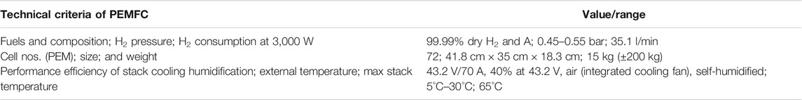
TABLE 1. Technical specifications of PEMFC.
2.2 Metal Hydride Tank
The metal hydride tank was made of Al alloy type EN-AA-6063 (MH_1500, Pragma Industries). It is filled with Ni-based AB5-type absorbent alloy that consisted of rare-earth and transitional metals. The chemical formula of the alloy is (LaCe)Ni5. The specifications of the MH tank are shown in Table 2. Nine kilograms of the alloy was loaded in the MH tank. The particle size of the alloy is 0.1 mm. The total weight of the MH tank is 13.15 kg with 9 kg of alloy, and its hydrogen capacity is 1,500 NL hydrogen. It is a one-chamber tank that used Cu that is connected to a water tube as a heat exchanger. A hydrogen connection tube is built-in for in/out of the hydrogen at the top side of the tank. A pressure gauge measures the charging and discharging pressures of the tank. To avoid contamination of hydrogen gas during the charging and discharging time of metal hydride, a middle layer is used. Charge and discharge flow rates were maintained at 10 slpm. A male quick connector is used to charge and discharge the tank.
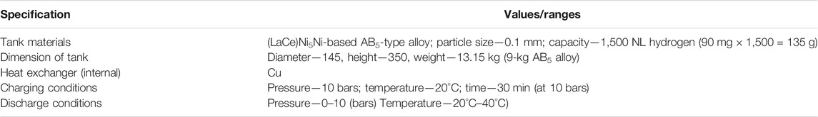
TABLE 2. Technical specifications of the MH tank.
The schematic diagram of the experimental apparatus used for this experiment is shown in Figure 1. The automatic purging valve, dedicated regulator, and ball valves enable the device to move between evacuation, activation, and charging–discharging processes. The lining device was eliminated using air as a carrier of volatiles before performing a hydrating activity.
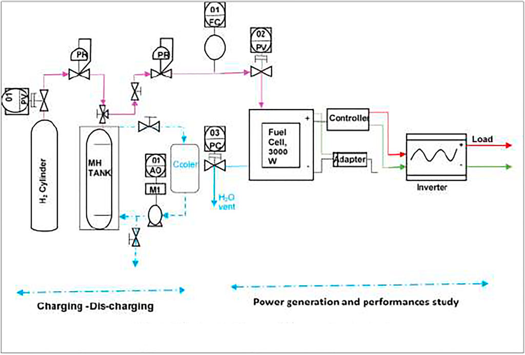
FIGURE 1. Schematic diagram of the experimental setup.
2.3 Method of Charging
MH tanks were charged at water and ice bath conditions. A compressed gas cylinder from Linde, Singapore, with a pressure of 200 bars is used to charge or induce hydride formation in the MH tank. A pressure of 10 bars and 10 slpm is maintained in the whole charging period of half an hour using a flammable regulator, MFC, and two- or three-way valve (according to the technical specification of the MH tank). A water bath (60 cm × 60 cm × 25 cm) with a water-holding capacity of 40 L was used. Charging temperature at water bath (20°C) and ice bath (0°C) was maintained with the help of a chiller. A pressure-regulated gas inlet/outlet passes through a 6-mm tubing. Three MH tanks (tank 1, tank 2, and tank 3/MH_1500) collected from Pragma Industries are used for charging and discharging investigations. All tanks are charged at 10, 8, and 6 bars with similar conditions to check the highest possible hydrogen storage and recorded charging pressure and temperature. Using thermocouple probes and pressure transducers, the temperature, reservoir pressure, and vessel were monitored.
2.4 Method of Discharging
Hydrogen discharge performances of the tank indicate the exact amount of usable hydrogen for the production of power by PEMFC. Discharging of the tanks was carried out at a tank pressure of 0–8 bars and temperature of 25°C–40°C, using a hydrogen process analyzer connected with PEMFC and a regulator to supply hydrogen to PEMFC at 0.5 bar and 10 slpm (according to fuel cell technical specification). All desorption tests followed after charging the MH tank and allowing it to cool to ambient temperature. Discharge or desorption of the tanks was conducted through a 3,000-W PEMFC (FCS-C3000, Horizon), consisting of 72 cells (specifications of PEMFC are tabulated in Table 2). Stack temperature, blowers, hydrogen input, purging, and fuel cell load were controlled by a control unit used in conjunction with an LCD.
Temperature and pressure of the MH tank were measured with a thermocouple and a pressure gauge built-in at the top of the tank. DC produced by PEMFC connected with the closed circuit is used for the load. An inverter is used to convert DC to AC for use through a bulb, fan, monitor, etc. MH tanks were heated by warm water flow (40°C) over the surface of the tank, and its whole desorption time was maintained, allowing to finish dehydration and stop the running of PEMFC.
3 Results and Discussion
3.1 Charging and Discharging Feature of the MH Tank
3.1.1 Charging/Storage Feature of MH Tank
Hydrogen storage capacities of MH tank at ice bath conditions and water bath conditions of 20°C have been investigated. Since hydride formation is an exothermic reaction, it produces heat. Charging at ice bath conditions, the temperature of tanks increases to 25°C in between the first 5 min and continues to increase incrementally to 30°C for the first 10 min. The rapid increase of the temperature of the MH tank is because of the large number of exothermic reactions of hydride formation. The temperature of the MH tank started to decrease at the 10th minute and further demonstrated a decrement to 20°C after another 5 min. A very slow decrement of MH tank temperature is observed for the next 30 min, whereas in the last 15 min, there is no change of temperature. Due to the formation of maximum metals to hydride, the trend of temperature increment is decreased and slowly it becomes saturated. Charging at water bath conditions (at 20°C), the tank temperature increased to 35°C for the first 5 min, as demonstrated in earlier conditions due to frequent hydride formation, and later slowly decreased as shown in Figure 2. Temperature decrement is observed until 30 min. After 30 min, there was no change of temperature for 15 min, and then it remained at 25°C due to the hydrogen saturation.
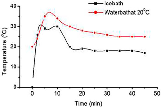
FIGURE 2. Hydrogen charging curves of metal hydride (MH) tank 2 at 0°C (ice bath) and 20°C (water bath) at 10 bars.
The amount of hydrogen stores in MH tanks is measured by the area under the curve. Experiments show a higher amount of hydrogen stores in the water bath conditions than in ice bath conditions. Further experimentation was continued for MH tanks at the water bath conditions due to better performances at 20°C.
Charging Feature of Tanks at 20°C
Three MH tanks (tank 1, tank 2, and tank 3) are charged at two conditions: an ice bath (0°C) and a water bath with a temperature of 20°C, with different pressures of 10, 8, and 6 bars accordingly. Storage capacities of MH tanks are enhanced at water bath conditions and 10-bar pressure. Figure 3 demonstrates the temperature profiles of three MH tanks charging at water bath conditions and 10-bar pressure. The profile shows that at the beginning, the temperature increased sharply due to the exothermic reaction of hydride formation in the initial phase of charging. The hydride formation process quickly discontinues because the equilibrium pressure of absorption increases with temperature increment over the hydrogen supply pressure. As a result, the temperature declined sharply due to the reduction of heat release through less hydride formation. A further sharp decline of temperature was observed after 720 s due to the slow formation of hydride in the second step of the equilibrium curve. Finally, it reached room temperature and remained in this state for a long time, which indicates the saturation of hydrogen and the formation of hydride in the alloy materials of MH tanks stopped. Charging experiments of MH tanks find a similar behavior of three MH tanks, where a sharp increment and two steps of decline in temperature despite having different profiles. It depends on the tank structure, activation conditions, charging conditions, heat exchange pipe properties, etc.
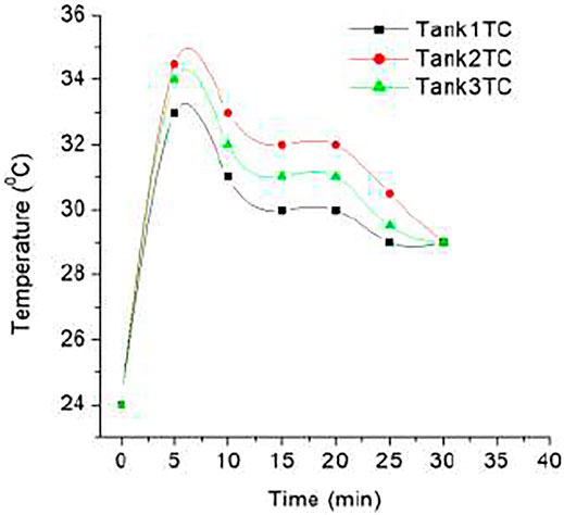
FIGURE 3. Hydrogen charging curves of three MH tanks at 20°C.
3.1.2 Discharge Feature
Three tanks (tanks 1, 2, and 3) were charged at similar conditions as mentioned above (Method of Discharging section). After being charged, the pressure of tanks 2 and 3 became stable at 6 bars, whereas the pressure of tank 1 became stable at 7 bars. Tank 2 discharge pressure sharply increased within 40 min and then dropped to 3 bars. Later, its pressure drops from 3 to 0 bar by 100 min and is maintained at 0 bar for 20 min. The discharging trend of MH tanks 1 and 3 is almost the same as tank 2 due to the similar AB5 material contents in the tanks. The best performance of the tank is because of the moisture-free physical adsorption in AB5-type materials.
Hydrogen storage/charging experiments have been conducted at a pressure 10 bars and 10 slpm flow rates. After charging MH tanks at 10 bars, the pressure of the tank slowly decreases. The stable pressure of charged MH tanks is 6–7 bars. Discharging of MH tank starts from 6 or 7 bars and 10 slpm flow rate, and 40°C temperature is maintained in the whole period (Figure 4). The discharge pressure of tank 2 begins at 6 or 7 bars and decreases slowly. The discharged hydrogen is consumed by PEMFC at 0.5 bar and 10 slpm. The 3-kW cell is connected in line that utilizes the constant volume of hydrogen that comes from dehydrating MH tank and produces electrical power. A constant load (250, 500, 1,000, and 2,000 W) is added with the PEMFC so that a constant consumption can be maintained. The MH tank that was charged at a water bath of 20°C and 10-bar pressure supplies hydrogen for 225 min (3.75 h). It shows pressure drop of 1 bar per 10 min until 5 bars and later took 40 min to reach 4 bars (Figure 5). It takes 95 min more to reach the 0-bar pressure of the tank and hydrogen flow rate drops to 8, 6, 4, 2, 1, and 0 bar. At 0 bar, the tank supplies hydrogen for 25 min more. Physically adsorbed large amounts of hydrogen in the alloy later desorbed slowly.
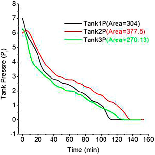
FIGURE 4. Hydrogen discharge curves of MH tanks at 40°C and 500-W load.
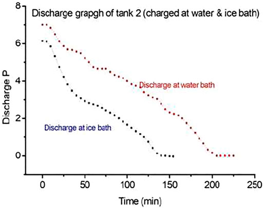
FIGURE 5. Discharge curves of MH tank 2 at 20°C water bath and ice bath.
In the second case, the stable pressure of tank 2 that was charged in an ice bath is 6 bars. It begins discharge with similar conditions, but the discharge feature is different. It only takes the first 10 min to drop the pressure to 5 bars. It gave a fixed amount of hydrogen supply to PEMFC for 35 min more to reach a pressure of 3 bars. It supplies hydrogen for 90 min more to drop the pressure to 0 bar. At 0 bar, the tank supplies hydrogen 19 min more for a similar experimental setup. There was a total of 154 min of continuous hydrogen supply to PEMFC to convert electrical power.
3.2 Absorption–Desorption Mechanism of MH Tank
Metal hydride hydrogen storage tank is loaded with several parts such as alloy powder, heat exchange parts, and gas transport components. The body of the container is generally aluminum alloy or stainless steel. The vessels used in this experiment are based on AB5 [(LaCe)Ni5] metal hydride alloy. The superiority of these vessels is their safe and reliable low-pressure storage, which is advantageous for portable applications and in-house and on-board storage (Hydrogen Storage. Hydroge, 2021).
During absorption, H2 molecules are set apart at the surface of the metal matrix and get inserted into the interstitial sites of the crystal structure (Westerwaal and Haije, 2008). Due to this phenomenon, the lattice of LaNi expands and causes strains and lattice defects. Thus, brittle materials are not a good choice for this process. During desorption, two hydrogen atoms recombine to H2 molecule (Figure 6). LaCeNi5 is particularly promising due to its ability to absorb and desorb hydrogen quickly within the required temperature and pressure ranges and with little hysteresis, which allows for a good life cycle (Schlapbach and Züttel, 2001). When used and stored in good conditions and filled with good-quality hydrogen (>99.99%), this tank has a life span of more than 2,000 cycles of discharge. However, hydrogen in (LaCe)Ni5H6 only has a mass density of 2%, meaning that the vast majority of the system is made up of LaCe and Ni.
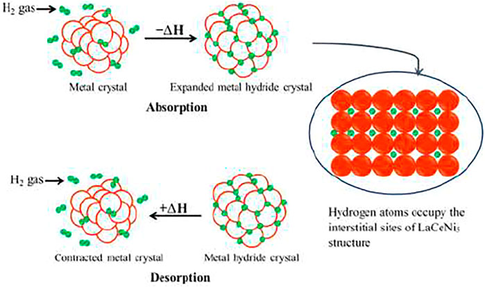
FIGURE 6. Adsorption and desorption mechanism of metal powder in a metal hydride storage tank.
Hydrogen is stored in the form of a metal hydride. Most metals or alloys can react with hydrogen to form new compounds, which are named metal hydrides. The formation of metal hydride is an exothermic process associated with heat releasing. With sufficient heat supply, hydrogen can be released from the as-formed metal hydride. Such a reversible reaction process can be expressed as follows:
Where M is the metal or alloy, MHn is metal hydride, and ΔH is the thermal effect associated with the reaction. When pressure and temperature change, the reaction will take place alternatively and hydrogen will be absorbed or desorbed. In the case of LaNi5-based storage, the reaction is as follows:
3.3 PEMFC Characteristics
The steady-state current vs. voltage curve of PEMFC represents the polarization curve of the cell. The curve defines three regions that are activation, ohmic, and mass transport region. The ideal shape of the polarization curve presents the right testing methods of a specific cell.
PEMFC degradation process is investigated using three V–I curves. Figure 7 depicts that activation loss makes up the most consumption of the PEMFC losses, and mass transport degradation takes the smallest portion among the three losses. The reason is that mass transport loss is mainly due to the impedance of reactant transport to catalyst sites, which causes the loss of gas-phase permeability in the porous layers of PEMFC. Based on the previous studies (Schlapbach and Züttel, 2001; Mehta and Cooper, 2003; Susta et al., 2003; Westerwaal and Haije, 2008; Hsieh et al., 2017a), large mass transport loss is usually associated with poor water management, such as cell flooding at high current density range.
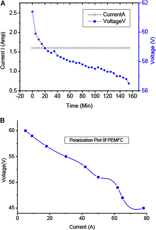
FIGURE 7. (A) Polarization (IV vs. time) curve of hydrogen discharge of MH tanks at 40°C and (B) polarization plot at the loaded period of PEMFC.
PEMFC (3,000 W) was connected with the load as shown in the figure, and hydrogen feed continues from the charged MH tank. MH tank 2 charged at a water bath of 20°C and 10-bar pressure supplies back/discharges hydrogen for 225 min (3.75 h), whereas the MH tank charged at an ice bath and 10-bar conditions supplies back or discharges hydrogen for 2.33 h (140 min) for the similar load and conditions. Charging the MH tank using the first conditions discharges hydrogen for a longer time for the same load. The performances of the MH tank at a water bath of 20°C and 10-bar conditions correspond to the optimum condition of hydrogen storage in the MH tank.
A different interpretation could be made in such a way that the amount of hydrogen consumed is directly proportional to the load demand. The stack consumes hydrogen through purging conditions at a particular interval (10 s or less than 10 s) in which a reaction occurs to produce power and waste hydrogen or steam purges out at the particular time. It is better observed than hydrogen consumption frequency increases for a higher load demand. Since the pressure and flow rate are controlled (fixed flow and pressure), higher consumption of hydrogen demands more frequency of purging hydrogen to the stack that reacts with oxygen to produce more power and to meet the higher load demand.
4 Discharge Characteristics at Different Loads
Figure 8 represents the discharge trend of the MH tank coupled with the 3-kW PEMFC employing different constant powers of i) 250, ii) 500, iii) 1,000, and iv) 2,000 W. A general trend of hydrogen consumption by a PEMFC stack is that the steady-state H2 flow has interfered with periodic purging impulses for the removal of liquid water from the anode side. The pressure drop of the tank is because of the purging of gases and utilizing it in the production of power. The frequency of the purging impulses varies with the fuel cell current that depends on the load. The impulses shorten when the current of the cell increases. The number of endothermic hydrogen desorption requires external heat to desorb efficiently. A standard operation requires a continuous hydrogen flow to the PEMFC. A similar volume of hydrogen MH tank discharges for a long time for the low-power load (250 W), whereas the MH tank sustains lesser time for higher stack power uses (500, 1,000, and 2,000 W) for higher load. The MH tank supplies H2 for 250, 500, 1,000, and 2,000-W load for 240, 160, 135, and 113 min, respectively. The shorter period of hydrogen discharge can be attributed to the high hydrogen flow rates, indicating a higher amount of hydrogen discharges that occurs for higher load. According to the experimental condition, the flow rate was controlled at 10 slpm that depends on the purging period of PEMFC. The consumption of hydrogen only sustains a longer period for low stack power or employed load. The thermal equilibrium of the MH tank bed with the room temperature will occur at the actual operation of the MH tank bed when the PEMFC operates periodically. For prolonged operation, heating the MH tank by ambient airflow is not enough to supply continuous H2 to the PEMFC, and a constant external heating is necessary for stable supply. The MH tank is loaded with 9 kg of hydride forming AB5-type materials that have a theoretical hydrogen storage capacity near 135 kg (1.5%). The discharge amounts of hydrogen for 250, 500, 1,000, and 2,000 W are 75, 72, 73, and 70 g of hydrogen, respectively, that represents an average discharge ratio of 55%.
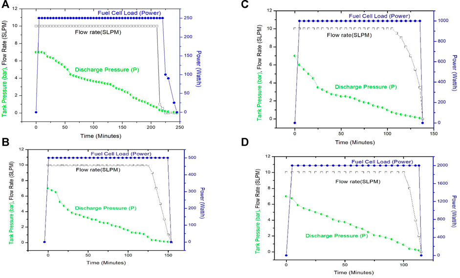
FIGURE 8. Discharge characteristics of MH tank 2 at different loads of (A) 250 W and (B) 500 W.
4.1 Cost of AB5-Type MH Tank
The cost of an MH tank with AB5-type solid metal hydride depends on the design of tank materials and performances of metal hydrides. This includes the packing density of the tank, the overall porosity of the hydride bed, and its thermal conductivity upon hydrogen uptake and release. According to the tank specifications (Table 2), it includes a double-coil-type heat exchanger of 20 m in length and a diameter of 0.5 in. The inner pressure of the tank can be measured by a pressure gauge. Two safety valves were set at the top and bottom. The total cost incurred to build an AB5-type metal hydride-containing tank is approximately $750.
5 Conclusion
The international demand to standardize and diversify the hydrogen fuel infrastructure is compelling many industries and sectors to adopt PEMFC and MH tanks. The enormous sources of hydrogen in Bangladesh are expected to boost the PEMFC and MH tank market shortly. Based on its application and increasing demand, the market of PEMFC and MH tanks is branching into stationary, transport, and so on. The international market share of PEMFC is 73% in 2020, which is very significant and promising. The Bangladesh market has a good potential to adopt and expand quickly. As a result, this combination will replace fossil fuel and reduce pollution that would help to implement a hydrogen economy. The present investigation corresponds that AB5-type (LaCe)Ni5 material-containing MH tank combined with PEMFC is a promising set up to be used in stationary and transportation sectors. A controlled hydrogen flow discharge rate and temperature (40°C) and charging in 20°C water bath with a controlled flow rate of 0.5 bar pressure are optimum conditions of the combined system of 3-kW PEMFC and 9 kg AB5-type MH-containing tank.
Data Availability Statement
The original contributions presented in the study are included in the article/Supplementary Files, and further inquiries can be directed to the corresponding author.
Author Contributions
All authors listed have made a substantial, direct, and intellectual contribution to the work and approved it for publication.
Conflict of Interest
The authors declare that the research was conducted in the absence of any commercial or financial relationships that could be construed as a potential conflict of interest.
Publisher’s Note
All claims expressed in this article are solely those of the authors and do not necessarily represent those of their affiliated organizations or those of the publisher, the editors, and the reviewers. Any product that may be evaluated in this article, or claim that may be made by its manufacturer, is not guaranteed or endorsed by the publisher.
Acknowledgments
The authors would like to gratefully acknowledge the Establishment of Hydrogen Energy Laboratory-Project, Bangladesh Council of Scientific and Industrial Research (BCSIR), Ministry of Science and Technology (MoST), Bangladesh, for laboratory and the financial support.
References
Abdalla, A. M., Hossain, S., Nisfindy, O. B. A. T., Dawood, M., Dawood, M., Azad, A. K., et al. (2018). Hydrogen Production, Storage, Transportation and Key Challenges with Applications: a Review. Energ. Convers. Manage. 165, 602–627. doi:10.1016/j.enconman.2018.03.088
Acres, G. J. K., Frost, J. C., Hards, G. A., Potter, R. J., Ralph, T. R., Thompsett, D., et al. (1997). Electrocatalysts for Fuel Cells. Catal. Today 38, 393–400. doi:10.1016/s0920-5861(97)00050-3
Balat, M. (2008). Potential Importance of Hydrogen as a Future Solution to Environmental and Transportation Problems. Int. J. Hydrogen Energ. 33, 4013–4029. doi:10.1016/j.ijhydene.2008.05.047
Barbir, F., and Gomez, T. (1996). Efficiency and Economics of Proton Exchange Membrane (PEM) Fuel Cellsiency and Economics of Proton Exchange Membrane (PEM) Fuel Cells. Int. J. Hydrogen Energ. 21, 891–901. doi:10.1016/0360-3199(96)00030-4
Barbir, F. (2009). Transition to Renewable Energy Systems with Hydrogen as an Energy Carrier☆. Energy 34, 308–312. doi:10.1016/j.energy.2008.07.007
Barreto, L., Makihira, A., and Riahi, K. (2003). The Hydrogen Economy in the 21st century: a Sustainable Development Scenario. Int. J. Hydrogen Energ. 28, 267–284. doi:10.1016/s0360-3199(02)00074-5
Bostic, E., Sifer, N., Bolton, C., Ritter, U., and Dubois, T. (2004). The US Army Foreign Comparative Test Fuel Cell Program. J. Power Sourc. 137, 76–79. doi:10.1016/j.jpowsour.2004.05.049
Cacciola, G., Antonucci, V., and Freni, S. (2001). Technology up Date and New Strategies on Fuel Cells. J. Power Sourc. 100, 67–79. doi:10.1016/s0378-7753(01)00884-9
Chalk, S. G., Miller, J. F., and Wagner, F. W. (2000). Challenges for Fuel Cells in Transport Applications. J. Power Sourc. 86, 40–51. doi:10.1016/s0378-7753(99)00481-4
Chauhan, A., and Saini, R. P. (2014). A Review on Integrated Renewable Energy System Based Power Generation for Stand-Alone Applications: Configurations, Storage Options, Sizing Methodologies and Control. Renew. Sustain. Energ. Rev. 38, 99–120. doi:10.1016/j.rser.2014.05.079
Chu, D., Jiang, R., Gardner, K., Jacobs, R., Schmidt, J., Quakenbush, T., et al. (2001). Polymer Electrolyte Membrane Fuel Cells for Communication Applications. J. Power Sourc. 96, 174–178. doi:10.1016/s0378-7753(01)00567-5
Costamagna, P., and Srinivasan, S. (2001). Quantum Jumps in the PEMFC Science and Technology from the 1960s to the Year 2000. J. Power Sourc. 102, 253–269. doi:10.1016/s0378-7753(01)00808-4
Costamagna, P., and Srinivasan, S. (2001). Quantum Jumps in the PEMFC Science and Technology from the 1960s to the Year 2000c Aspects. J. Power Sourc. 102, 242–252. doi:10.1016/s0378-7753(01)00807-2
Demirbas, A. (2001). Biomass Resource Facilities and Biomass Conversion Processing for Fuels and Chemicals, 1357–1378.
Docter, A., and Lamm, A. (1999). Gasoline Fuel Cell Systems. J. Power Sourc. 84, 194–200. doi:10.1016/s0378-7753(99)00317-1
Eliezer, D., Eliaz, N., Senkov, O. N., and Froes, F. H. (2000). Positive Effects of Hydrogen in Metals. Mater. Sci. Eng. A 280, 220–224. doi:10.1016/s0921-5093(99)00670-x
Energypedia Energy Scenario Bangladesh 2017-18 (2017). Available at: www.hcu.org.bd
Faur Ghenciu, A. (2002). Review of Fuel Processing Catalysts for Hydrogen Production in PEM Fuel Cell Systems. Curr. Opin. Solid State. Mater. Sci. 6, 389–399. doi:10.1016/s1359-0286(02)00108-0
Gamburzev, S., and Appleby, A. J. (2002). Recent Progress in Performance Improvement of the Proton Exchange Membrane Fuel Cell (PEMFC). J. Power Sourc. 107, 5–12. doi:10.1016/s0378-7753(01)00970-3
Gray, P. G., and Frost, J. C. (1998). Impact of Catalysis on Clean Energy in Road Transportation. Energy Fuels 12, 1121–1129. doi:10.1021/ef980110f
Holladay, J. D., Hu, J., King, D. L., and Wang, Y. (2009). An Overview of Hydrogen Production Technologies. Catal. Today 139, 244–260. doi:10.1016/j.cattod.2008.08.039
Hsieh, C.-Y., Nguyen, X.-V., Weng, F.-B., Kuo, T.-W., Lee, C.-Y., and Su, A. (2017). Developing Hybrid-Power Fuel Cells with a Low-Pressure Hydrogen-Storage System Used in an Electric Forklifts. Int. J. Electrochem. Sci. 12, 6266–6281. doi:10.20964/2017.07.54
Hydrogen Storage. Hydrogen Storage, (2021). Available at: https://www.pragma-industries.com/hydrogen-storage
Jain, I. P. (2009). Hydrogen the Fuel for 21st century. Int. J. Hydrogen Energ. 34 (17), 7368–7378. doi:10.1016/j.ijhydene.2009.05.093
Lattin, W. C., and Utgikar, V. P. (2007). Transition to Hydrogen Economy in the United States: a 2006 Status Report. Int. J. Hydrogen Energ. 32, 3230–3237. doi:10.1016/j.ijhydene.2007.02.004
Li, J., Huang, H., Kobayashi, N., He, Z., and Nagai, Y. (2014). Study on Using Hydrogen and Ammonia as Fuels: Combustion Characteristics and NOx formation. Int. J. Energ. Res. 38, 1214–1223. doi:10.1002/er.3141
Mehta, V., and Cooper, J. S. (2003). Review and Analysis of PEM Fuel Cell Design and Manufacturing. J. Power Sourc. 114 (1), 32–53. doi:10.1016/s0378-7753(02)00542-6
Midilli, A., Ay, M., Dincer, I., and Rosen, M. A. (2005). On Hydrogen and Hydrogen Energy Strategies. Renew. Sustain. Energ. Rev. 9, 255–271. doi:10.1016/j.rser.2004.05.003
Mohsenian, S., Esmaili, M. S., Fathi, J., and Shokri, B. (2016). Hydrogen and Carbon Black Nano-Spheres Production via thermal Plasma Pyrolysis of Polymers. Int. J. Hydrogen Energ. 41, 16656–16663. doi:10.1016/j.ijhydene.2016.05.150
Muellerlanger, F., Tzimas, E., Kaltschmitt, M., and Peteves, S. (2007). Techno-economic Assessment of Hydrogen Production Processes for the Hydrogen Economy for the Short and Medium Term. Int. J. Hydrogen Energ. 32, 3797–3810. doi:10.1016/j.ijhydene.2007.05.027
P Cardoso, D. S., Amaral, L., F Santos, D. M., Sljukic, B., Sequeira, C. A. C., and Maccio, D. (2015). Enhancement of Hydrogen Evolution in Alkaline Water Electrolysis by Using Nickel-Rare Earth Alloys. Int. J. Hydrogen Energ. 34, 231–237. doi:10.1016/j.ijhydene.2015.01.174
Radecka, M., Wnuk, A., T Zajac, A., and Schneider, K. (2015). TiO2/SnO2 Nanotubes for Hydrogen Generation by Photo Electrochemical Water Splitting. Int. J. Hydrogen Energ. doi:10.1016/j.ijhydene.2014.09.154
Ramachandran, R., and K Menon, R. (1998). An Overview of Industrial Uses of Hydrogen. Int. J. Hydrogen Energ. 23, 593–598. doi:10.1016/s0360-3199(97)00112-2
Richards, M., and Shenoy, A. (2007). H2-Mhr Pre-conceptual Design Summary for Hydrogen Production. Nucl. Eng. Tech. 39 (1), 1–8. doi:10.5516/net.2007.39.1.001
Salam, M. A., Ahmed, K., Akter, N., Hossain, T., and Abdullah, B. (2018). A Review of Hydrogen Production via Biomass Gasification and its prospect in Bangladesh. Int. J. Hydrogen Energ. 43 (32), 14944–14973. doi:10.1016/j.ijhydene.2018.06.043
Schlapbach, L., and Züttel, A. (2001). Hydrogen-Storage Materials for Mobile Applications. Nature 414, 353–358. doi:10.1038/35104634
Sobrino, F. H., Monroy, C. R., and Pérez, J. L. H. (2010). Critical Analysis on Hydrogen as an Alternative to Fossil Fuels and Biofuels for Vehicles in Europe. Renew. Sustain. Energ. Rev. 14, 772–780. doi:10.1016/j.rser.2009.10.021
Susta, M. R., Luby, P., and Mat, S. B. (2003). Biomass Energy Utilization & Environment protection Commercial Reality and Outlook Power-Gen Asia.
Veziroğlu, T. N. (2008). 21st Century's Energy: Hydrogen Energy System. Energy Convers Manag 49, 1820–1831.
Krause, P. C., Wasynczuk, O., and Sudhoff, S. D. (2013). Analysis of Electric Machinery and Drive Systems. Hoboken, NJ, United States: John Wiley & Sons.
Wang, L. (2003). A Parametric Study of PEM Fuel Cell Performances. Int. J. Hydrogen Energ. 28 (11), 1263–1272. doi:10.1016/s0360-3199(02)00284-7
Westerwaal, R. J., and Haije, W. G. (2008). Evaluation Solid-State Hydrogen Storage Systems. ECN, Pette. ECN-E-08-043April.
Keywords: proton-exchange membrane fuel cell, metal hydride tank, dehydrogenation, optimum condition, combined system
Citation: Salam MA, Islam T, Ahmed K, Sahab uddin M, Habib S and Abdullah B (2021) Potential Feature of Combined AB5-Type Metal Hydride Tank and PEMFC as a Safer System for Hydrogen Fueling in Bangladesh. Front. Energy Res. 9:766270. doi: 10.3389/fenrg.2021.766270
Received: 28 August 2021; Accepted: 26 October 2021;
Published: 26 November 2021.
Edited by:
Lin Zeng, Southern University of Science and Technology, ChinaReviewed by:
Raman Vedarajan, International Advanced Research Centre for Powder Metallurgy and New Materials, IndiaQian Xu, Jiangsu University, China
Copyright © 2021 Salam, Islam, Ahmed, Sahab uddin, Habib and Abdullah. This is an open-access article distributed under the terms of the Creative Commons Attribution License (CC BY). The use, distribution or reproduction in other forums is permitted, provided the original author(s) and the copyright owner(s) are credited and that the original publication in this journal is cited, in accordance with accepted academic practice. No use, distribution or reproduction is permitted which does not comply with these terms.
*Correspondence: Md Abdus Salam, salam.bcsir1@gmail.com