Flow Conditioning to Control the Effects of Inlet Swirl on Brush Seal Performance in Gas Turbine Engines
 Yuxin Liu
 Wenlei Dong1
  Michael Pekris
- 1Marine Engineering College, Dalian Maritime University, Dalian, China
- 2Naval Architecture and Ocean Engineering College, Dalian Maritime University, Dalian, China
- 3Department of Mechanical Engineering Sciences, University of Surrey, Guildford, United Kingdom
When subject to highly swirling inlet flow, the bristles on the upstream face of a brush seal in gas turbine engines tend to slip circumferentially, which may lead to aeromechanical instability and seal failure. In this article, a new design of the front plate of brush seal, which mitigates this effect, is presented. Angled ribs on the upstream side of the front plate are used to reduce the swirl of the flow impacting on the bristle pack. The effects of the rib geometry, including angle of inclination and height-to-spacing ratio, are investigated using computational fluid dynamics, and a bulk porous medium model of the bristle pack, on a simple seal geometry. Results show that the ribs can effectively regulate the flow upstream of the bristle pack, reducing the swirl and channeling flow radially inward to the sealing section, resulting in decreased circumferential forces on the bristles. Ribs inclined at 20° to the radial direction and with height-to-spacing ratio of 0.4 were selected as the most effective of those investigated for the seal geometry under study. A model of an aeroengine preswirled cooling air chamber was created to give insight into the inlet swirl boundary conditions that a preswirl seal brush seal could be subjected to at a range of leakage flow rates and inlet swirl velocities. The new design and upstream roughness feature substantially reduced inlet swirl velocity incident on the bristle pack. The findings in this work could have a significant impact on brush seal design and, in particular, mitigate a significant operational risk of swirl-induced instability in high-pressure, high-speed shaft seal locations.
Introduction
Brush seals are used for sealing between rotating and stationary components in applications with high-speed rotating shafts such as aeroengines. As reported by Chupp et al. (2002), compared to traditional labyrinth seals (Asok et al., 2008), brush seals improve sealing performance by reducing the leakage rate to 10% to 20% that of the latter. However, other performance factors such as wear, stability, and in-service deterioration have, to date, limited the application of brush seals (Aslanzada et al., 2009). Further research and development are needed to understand and improve these aspects so that brush seals can achieve their full potential.
A basic brush seal design includes a front plate, backing ring, and bristle pack, as shown in Figure 1. In order to reduce the wear between the bristles and the rotor and make it easier for the bristles to adapt to the radial movement of the rotor, the bristles are typically inclined at 30°–60° (ϕ) to the radial direction in planes of constant axial position. In operation, the bristle tips are often in contact or near-contact with the rotor, due to blowdown of the sealing elements, so that a significant proportion of the leakage flow passes through the bristle pack. The tortuous, narrow flow path between the bristles and the small radial clearance with the rotor, if any, provides resistance to the flow, thereby achieving good sealing performance.
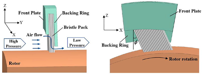
FIGURE 1. Basic brush seal.
The detailed behavior of the bristle pack in a brush seal depends on complex aeromechanical interactions. Even with known aerodynamic forces, calculation of bristle deflections is a challenging problem. For example, Zhao and Stango (2007) reported that the reaction and frictional forces between bristles and rotor, bristles, and backing plate and between adjacent bristles affect the deformations. The frictional forces cause pack stiffness and hysteresis and are particularly challenging to model accurately. A number of approaches to modeling of mechanical aspects have been presented in the literature. Crudgington et al. (2012) established a three-dimensional (3D) mechanical model to estimate the reaction forces and bristle deflection, showing that hysteresis and aerodynamic loading are the dominant factors for the sealing performance. Guardino and Chew (2004) and Lelli et al. (2006) developed 3D computational fluid dynamics (CFD) and 3D bristle bending models for brush seals, demonstrating the potential to investigate bristle pack deformation under aerodynamic loading. Sun et al. (2016) also developed a 3D coupled CFD-mechanical model and used this to investigate the effects of geometric parameters on the leakage characteristic of brush seals.
For less detailed and more computationally efficient modeling of leakage flow and aerodynamic effects, porous medium representations of the bristle pack are often used within CFD models, Bayley and Long (1993), Wei et al. (2015), and Gresham et al. (2016) introduced a leakage based on a linear porous medium model for comparison with their experimental results. Chew et al. (1995) proposed a nonlinear, anisotropic porous treatment and calibrated the viscous and inertial coefficients with experimental data. Chew and Hogg (1997) further explored the choice of coefficients considering leakage data for a wider set of experiments. Dogu and Aksit (2006) and Dogu et al. (2016) also developed the porous medium method and analyzed the effects of different front plate and bristle geometrical parameters and operating conditions on the leakage flow characteristics of brush seals.
A very limited number of studies have considered brush seal behavior in highly swirling environments. Sharatchandra and Rhode (1996) and Helm et al. (2008) found that brush seals could weaken the swirling flow, which can benefit shaft dynamic stability (Ramakrishna and Govardhan, 2008). However, lift forces are generated on the bristles, and this could cause instability of the upstream bristles and deterioration in performance. Considering possible aerodynamic instability and seal failure, Liu et al. (2020) analyzed the effect of inlet swirl on the bristle deflection using the Surrey University Brush Seal Iterative Simulator, a coupled 3D CFD and mechanical model. Results indicated that slip and possible instability of the upstream bristle row can be correlated with inlet swirl dynamic head. A plane front plate exacerbated this effect. As shown in Figure 2, the swirl of the flow entering the pack near the bristle tips increased in the presence of the front plate. It was proposed that introducing roughness elements on the upstream surface of the plate could reduce the swirl of flow impacting on the bristles and thereby improve the stability of the seal.
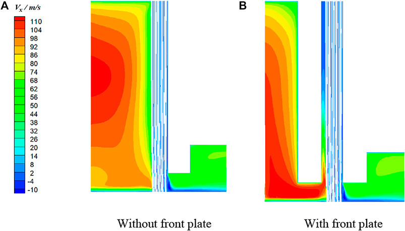
FIGURE 2. Circumferential velocity contours (SV = 150 m/s): (A) without front plate, (B) with front plate.
Based on the conclusions above, this article further explores the use of flow conditioning to mitigate the effects of inlet swirl on seal stability. A porous medium model is adopted for the bristle pack, and a front plate with inclined ribs attached on the upstream face is introduced. The effect of the front plate rib geometry on the velocity field, pressure field, and leakage flow of the brush seal under high swirl conditions is investigated in this study. The optimal rib geometry from the parametric study is then evaluated in a model of a turbine cooling air preswirl chamber.
CFD Modeling
Geometry and CFD Mesh Generation for Parametric Study
A brush seal structure including a front plate equipped with ribs is considered in this article, as presented in Figure 3. The geometric parameters are based on the brush seal considered in reference (Liu et al., 2020) and summarized in Table 1. In the initial parametric study, the curvature of the shaft and the rotation of the rotor are neglected, assuming also that there is a zero clearance between the bristle pack and the shaft. As shown in the Figure 3, X, Y, and Z coordinates represent the circumferential, axial, and radial directions, respectively, in a finite radius seal, and this terminology is used here despite the neglect of curvature. The model assumes periodicity in the circumferential direction.
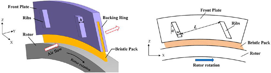
FIGURE 3. Schematic of a brush seal and front plate with ribs.
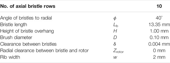
TABLE 1. Brush seal geometry parameters.
The geometric parameters of the ribs include the angle (α), height (h), spacing (L), and width (w), as can be seen in Figure 3. The width and height can be nondimensionalized by dividing by the rib spacing. In this way, the determined geometric parameters of ribs can be considered as angle of inclination, height-to-spacing ratio, and width-to-spacing ratio. The angle of inclination relative to the inlet airflow (swirl) direction and the height-to-spacing ratio are expected to strongly affect the flow deflection and degree of separation in the channels between the ribs. Hence, the discussion of the results will focus on these parameters. The base geometry is for ribs with inclination angle to the radial direction of 20°, height-to-spacing ratio of 0.2 (h = 2 mm, L = 10 mm). The values of the geometric parameters considered are summarized in Table 2.
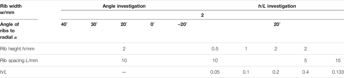
TABLE 2. Rib geometry parameters.
Figure 4 shows the calculation domain and mesh for the brush seal with front plate and ribs. ICEM software was used to generate a hexahedral mesh. The mesh is refined through the seal and around the ribs. Further details of the porous medium model used for the bristle pack and boundary conditions are given below. In order to investigate grid dependency, meshes with approximately 6 million, 8 million, and 10 million cells were considered for the base geometry. The applied boundary conditions for the base case are specified in Numerical Methods and Modeling Assumptions, including an inlet swirl velocity of 150 m/s. To examine the grid dependence, averaged swirl velocity at specific axial planes and leakage flow rates were examined. Figure 5 compares area-averaged swirl velocity for the three meshes. Differences between the meshes are within 3%, and the difference of mass flow rates is less than 0.5%. The 8-million-cell mesh is used for the calculations in the current study.
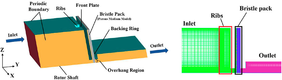
FIGURE 4. CFD domain and mesh for the base geometry.
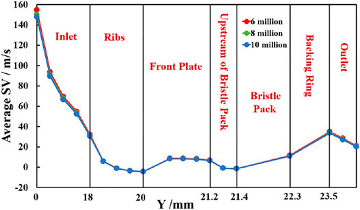
FIGURE 5. Swirl velocity result for three different meshes.
Numerical Methods and Modeling Assumptions
The commercial CFD software FLUENT was used to obtain 3D, steady numerical solutions of the flow and energy equations using the k-ε turbulence model and second-order upwind spatial discretization. The fluid was modeled as an ideal gas representing air, with specific heat and viscosity given as functions of temperature. At the inlet, boundary conditions of 0.5 MPa total pressure, 300 K total temperature, and 150 m/s circumferential (swirl) velocity were applied. A static pressure of 0.1 MPa was specified at the outlet. Periodic boundary conditions were applied in the circumferential direction, and all further boundaries were assumed to be no-slip and adiabatic. Shaft rotation was not considered in the parametric study but was included in the preswirl chamber application described later. Standard wall functions were used when imposing the no-slip condition on walls, and the equations were solved using the SIMPLE algorithm. The values of y+ for the walls are in the range of 20–30. The calculations were considered to be converged when the residuals of the continuity equation, energy equation, and turbulence equations had all decreased to 10−5 and typical parameters, such as pressure, velocity, and flow rate, no longer changed.
Porous Medium Model
The bristle pack is composed of layers of fine bristles, which are densely packed, typically in a hexagonally close packed arrangement. The airflow passes through the fine gaps between the bristles driven by the pressure difference across the seal. As the main interest here is on the condition of the flow approaching the bristles, rather than the detailed flow within the pack, an approximate treatment of seal flow is used. Following previous studies (Chew et al., 1995; Chew and Hogg, 1997; Zhang et al., 2017), a nonlinear porosity model is used to simulate the flow through bristle pack by introducing viscosity and inertia losses into the momentum equation, giving
In Eq. 2, Aij is the matrix of viscous resistance coefficients, and Bij is the matrix of inertial resistance coefficients. Principal coordinates for the matrices are taken to be z, m, and n. These are the axial direction for the brush seal, parallel to the bristles, and perpendicular to the bristles in an axial plane, respectively. Following reference (Pugachev, 2014), the viscous resistance coefficients a and inertial resistance coefficients b are obtained as follows:
Porosity (ε) refers to the ratio of the void volume to the total volume of the bristle pack in the porous medium and is given by
In this equation, N is the number of the bristles per unit circumferential length, D is the diameter of the bristles, wb is the thickness of the bristle pack, and ϕ is the angle between the bristle and the tangential direction. The expressions for resistance coefficients were validated by experiments in reference (Turner et al., 1998). Based on the geometric parameters in Table 1, the porosity of the bristle pack in the current study is 0.192.
Numerical Method Validation
Comparisons of results from the present model with Bayley and Long (1993) and Turner et al. (1998), experimental data and previously published modeling results are plotted in Figure 6. The calculation model and the boundary conditions for validation were consistent with the experiment (Bayley and Long, 1993; Turner et al., 1998). Figure 6A compares the leakage flow for a brush seal with radial clearances c = 0 mm, 0.27 mm between the bristle tip and rotor for pressure ratios (Rp) 1 to 4. The nondimensional pressure variation along the radial backing plate, which is defined as p∗ = (p − poutlet)/(pinlet − poutlet), is shown in Figure 6B. The calculated leakage and pressure distribution are in good agreement with the experimental data and other workers’ numerical results.
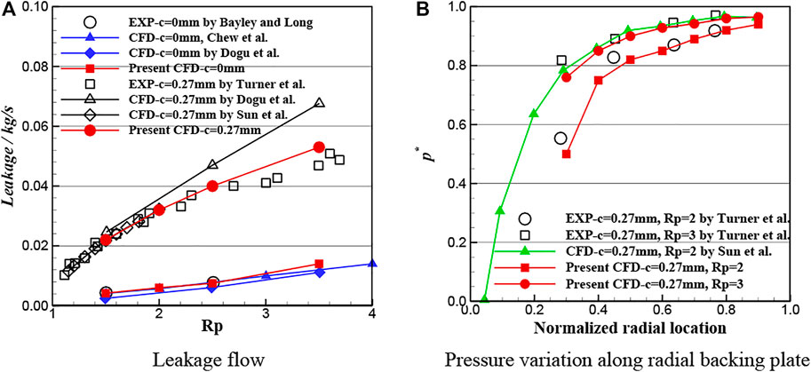
FIGURE 6. Comparisons of present results with previously published data: (A) leakage flow, (B) radial pressure distribution on backing plate.
Parametric Study
The following subsections discuss the effects of ribs including variations in angle and height-to-spacing ratio on inlet swirl. The flow field upstream of the bristle pack is analyzed with particular attention given to the swirl velocity. Predicted leakage flow rates for all cases agreed to be within 1.5%. The four viewing surfaces used to visualize the flow contours and streamlines are shown in Figure 7; they are surfaces cutting through the middle of ribs (surfaces 1–3) and 0.2 mm upstream of the bristle pack (surface 4).
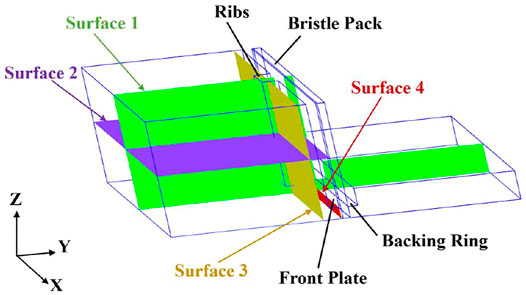
FIGURE 7. Viewing surfaces for flow visualization.
Effect of Ribs for Base Geometry
Figure 8 shows swirl velocity contours on surface 1 for the base geometry with and without ribs. The comparison shows that the ribs have a significant effect upstream of the bristle pack, with the ribs reducing swirl velocities considerably. This is expected as the ribs act as roughness elements exerting drag on the flow. The area averaged swirl velocity on surface 4, just upstream of the bristle pack, is reduced from 50.9 to 6.5 m/s due to the presence of the ribs. Thus, the circumferential aerodynamic forces on the bristles, which scale with swirl dynamic head (Liu et al., 2020), are expected to be reduced by a factor of approximately 60.
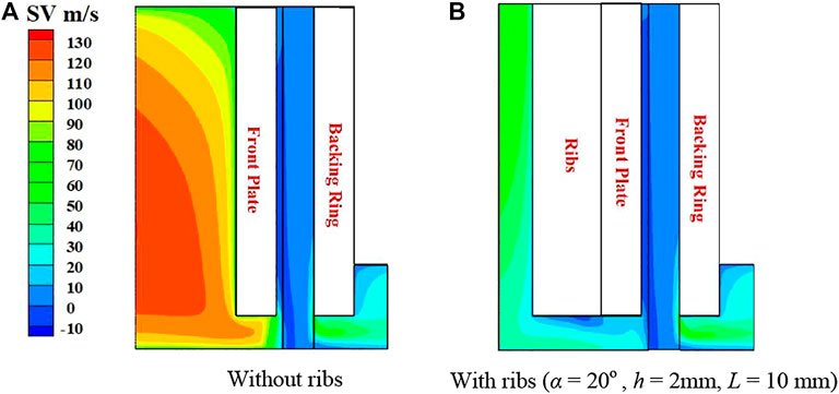
FIGURE 8. Swirl velocity contours for base geometry on surface 1: (A) without ribs, (B) with ribs (α = 20°, h = 2 mm, L = 10 mm).
Effect of the Rib Angle
In order to examine the effect of rib angle on flow, five rib inclination angles (−20°, 0°, 20°, 30°, 40°) were considered. Figure 9 shows the variation of mass-averaged total pressure distribution along the axial direction for the five rib lay angles and the case without ribs. Approaching the seal, total pressure is significantly reduced for the front plate brush seals with ribs. This is due to the spoiling effect of the ribs, leading to dissipation of the flow kinetic energy. The total pressure variation is similar for the five rib lay angles, with the larger angle cases showing the greater departure from the smooth front plate case. This may be due to the larger angle ribs inducing more recirculation in the inlet region. As expected, once the flow enters the pack, the effects of inlet swirl rapidly diminish due to the strong resistance to circumferential flow. It is the ratio of tangential to axial aerodynamic force on the upstream bristles that determines circumferential slip and aeromechanical instability (Liu et al., 2020). Although this ratio might be estimated from the porous model, this has not been attempted here as swirl velocity immediately upstream of the bristles is considered sufficient to indicate the performance of the ribs and of the normal aerodynamic force acting to displace the bristles. As shown in the Figure 9, the pressure drops rapidly through the bristle pack to the downstream pressure.
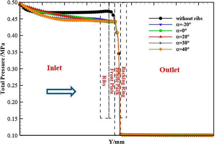
FIGURE 9. Average total pressure variation with rib angle (h = 2 mm, L = 10 mm).
Figure 10 shows streamlines and swirl velocity contours on surface 3 for the five rib angles. The cross-flow due to the inlet swirl (from left to right) creates flow separation and vortices between the ribs. For the negative lay angle of −20°, the ribs deflect the flow radially outward, creating an anticlockwise flow in the axial plane. Below the rib bottom where the bristle pack is exposed, swirl velocity is reduced from that without the ribs in Figure 8, but it is still substantial. For the radial ribs with lay angle 0°, the outward flow is less extensive. The center of the major circulation between the ribs moves outward and creates a second smaller vortex. There is a significant reduction of swirl near the seal inlet. For positive rib angles, the ribs deflect the flow radially inward toward the seal creating a clockwise flow vortex in the plane. The positive rib angles are clearly more effective in reducing swirl near the shaft and seal inlet. As the rib angle increases, the extent of the radially deflected flow region in this plane also increases, and the swirl velocity beneath the rib tip is seen to increase.
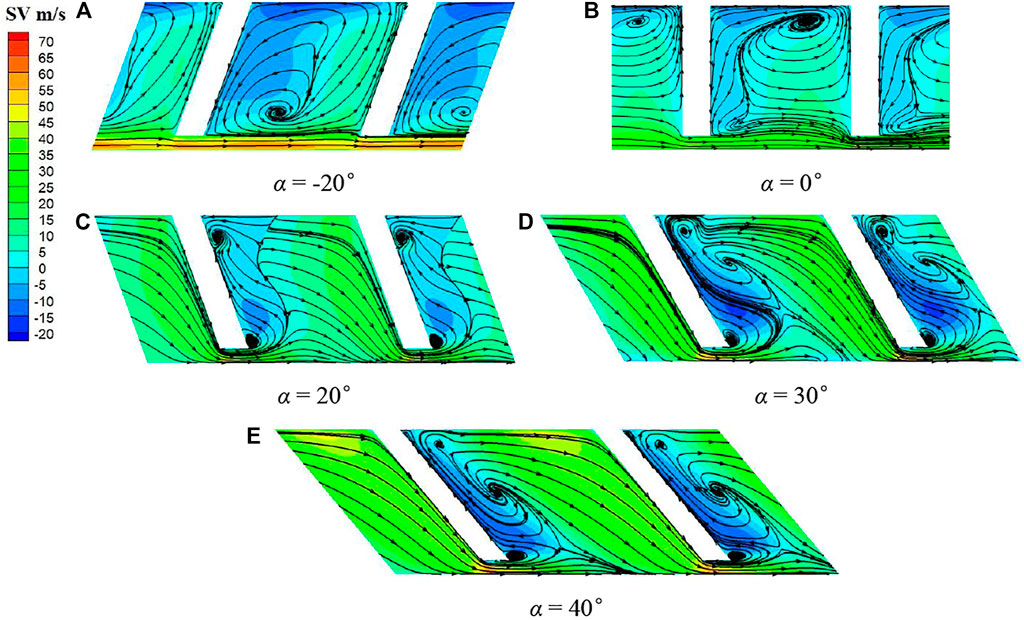
FIGURE 10. Swirl velocity contours and streamlines on surface 3 (h = 2 mm, L = 10 mm): (A) α = −20°, (B) α = 0°, (C) α = 20°, (D) α = 30°, (E) α = 40°.
To further illustrate the effect of ribs, contours of swirl velocity on the portion of surface 1 just upstream of the bristle tips, which aligns with the rib centerline where the peak velocities are observed to occur, are shown in Figure 11. It can be seen that for α = −20°, 30°, and 40°, the circumferential velocity remains high, although Figure 10 shows that away from the rib tips swirl velocities for α = 30° and 40° are low. Note also that the contour scale here differs from that in Figure 8, and the swirl for all ribbed cases is below that for the plane front plate.
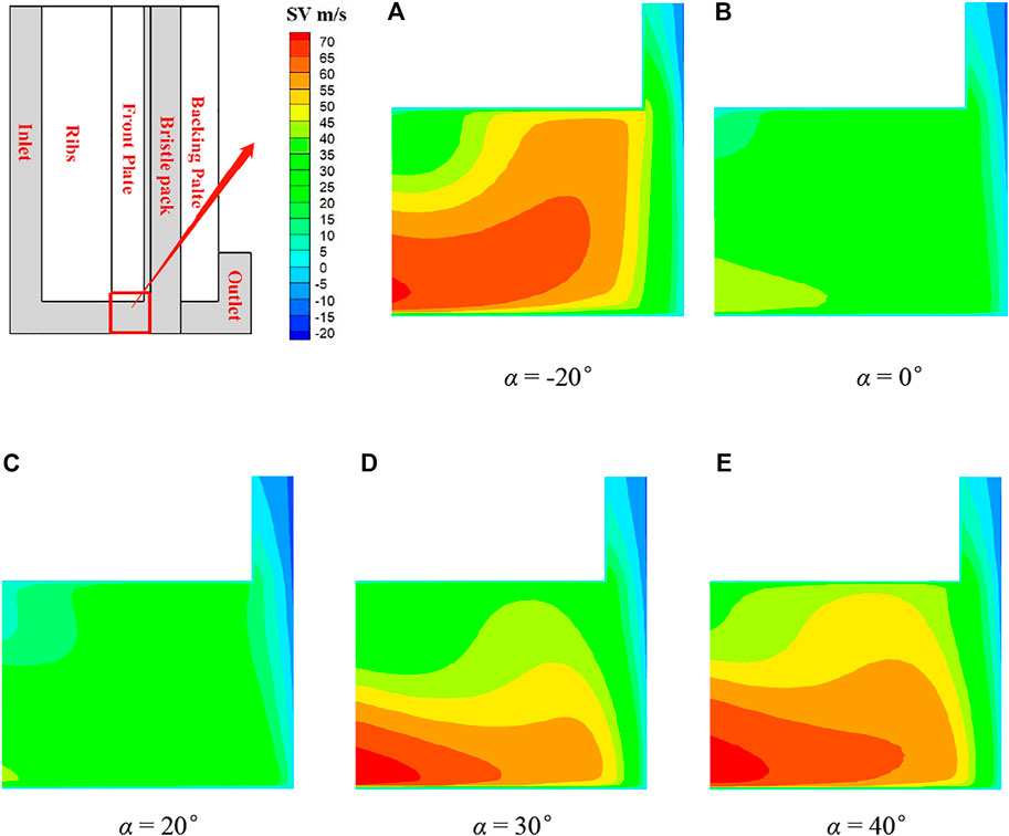
FIGURE 11. Swirl velocity contours on surface 1 (h = 2 mm, L = 10 mm): (A) α = −20°, (B) α = 0°, (C) α = 20°, (D) α = 30°, (E) α = 40°.
The trends observed above are further illustrated in Figure 12 and Table 3. Figure 12 plots the area-averaged swirl velocities on planes of constant axial position for the five rib angles and the plane front plate. Table 3 gives the average and maximum swirl velocities on the plane 0.2 mm upstream of the bristle pack (surface 4). The average and maximum swirls approaching the seal are significantly lower than with the plain front plate for all the ribbed cases. The average swirl velocity changes sharply at the start of the ribbed and front plate axial sections. Once the flow is established downstream of the ribs, the average swirl remains almost constant until the flow enters the bristle pack. The maximum swirl values in Table 3 confirm that the high local values observed in Figure 10 for α = 30° and 40° persist close to the bristle pack. The parametric study shows that the 20° angled ribs are most effective in reducing the swirl of the flow onto the bristle pack.

FIGURE 12. Average swirl velocity variation with rib angle (h = 2 mm, L = 10 mm).
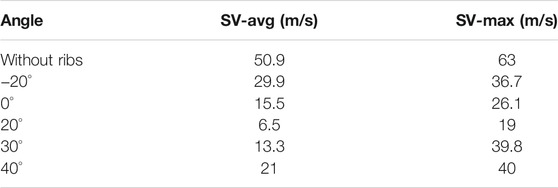
TABLE 3. Variation of swirl velocity on surface 4 with rib angle.
Effect of Rib Height-to-Spacing Ratio
In this section, the rib height-to-spacing ratio was investigated by varying rib height first for the same spacing and then keeping the rib height constant with changing rib spacing. Therefore, the effect of rib height (h = 0.5, 1, 2 mm) on the seal inlet swirl was studied for the rib angle of 20° and rib spacing of 10 mm (h/L = 0.05, 0.1, 0.2). Figure 13 shows the streamlines and swirl velocity contours on surface 2. As expected, the extent of the separated flow region downstream of the ribs increases with rib height. For h = 2 mm (h/L = 0.2), the flow does not fully reattach between the ribs.
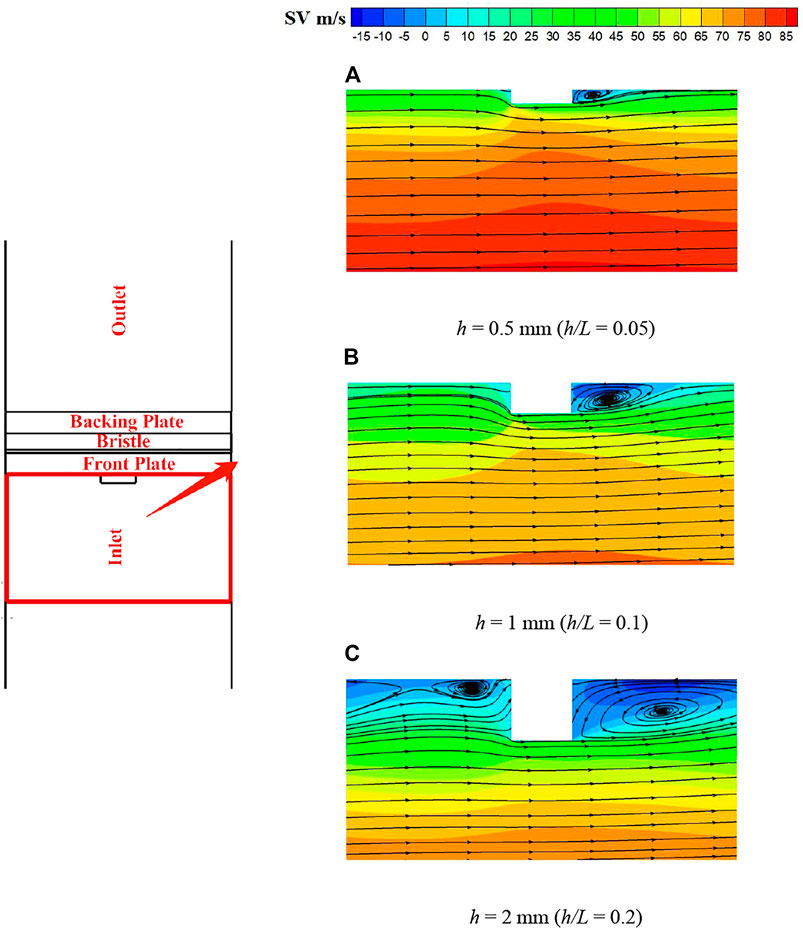
FIGURE 13. Swirl velocity contours and streamlines on surface 2 (α = 20°, L = 10 mm): (A) h = 0.5 mm (h/L = 0.05), (B) h = 1 mm (h/L = 0.1), (C) h = 2 mm (h/L = 0.2).
Figure 14 shows the average swirl velocity with the same overall trends as in Figure 12. The average seal inlet swirl is reduced significantly more for h = 2 mm (h/L = 0.2) than at the lower rib heights. Table 4 gives the average and maximum swirl velocities on the plane 0.2 mm upstream of the bristle pack. Although the effectiveness of the ribs at this angle reduces with decreasing height, the smaller ribs are still as effective in reducing maximum swirl as the 2-mm ribs at higher angles.
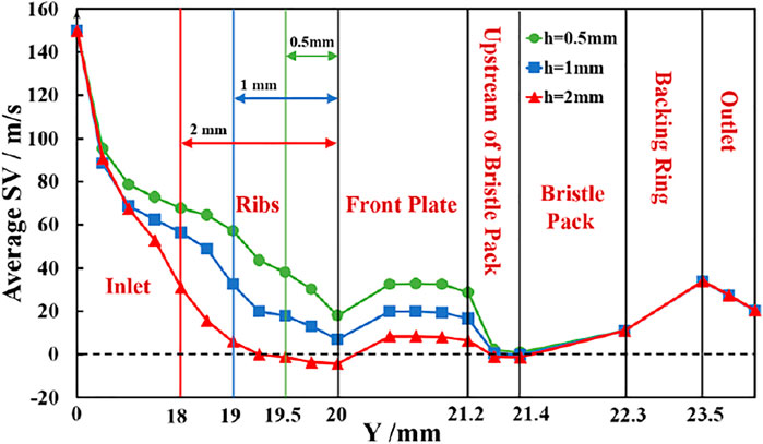
FIGURE 14. Averaged swirl velocity variation with rib height (α = 20°, L = 10 mm).
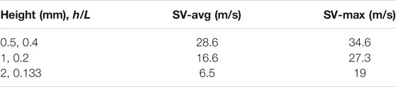
TABLE 4. Variation of swirl velocity on surface 4 with rib height.
Three different rib spacings (L = 5, 10, 15 mm) were considered for ribs with an inclination angle of 20° and a height of 2 mm (h/L = 0.4, 0.2, 0.133). Figure 15 presents the streamlines and swirl velocity contours on surface 3 for the different spacings. As previously shown, flow separation occurs downstream of the ribs, and at the wider spacings, a local maximum in swirl forms between the tip of the rib and the shaft. At a rib spacing of 5 mm (h/L = 0.4), the airflow between the ribs is more uniformly radially inward, and this produces opposing vortices below the rib tip, with reduced swirl compared to the wider spacings.
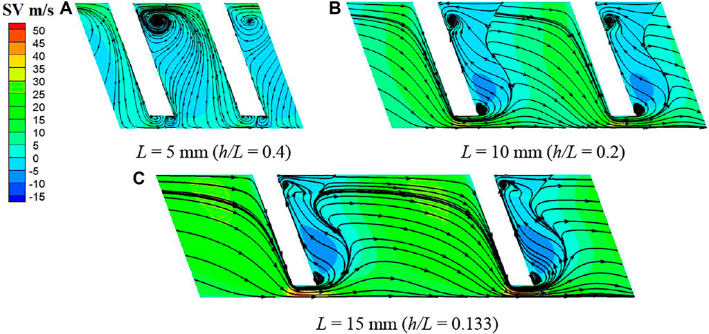
FIGURE 15. Swirl velocity contours and streamlines on surface 3 (α = 20°, h = 2 mm): (A) L = 5 mm (h/L = 0.4), (B) L = 10 mm (h/L = 0.2), (C) L = 15 mm (h/L = 0.133).
Figure 16 shows the average swirl velocity for the three rib spacings. It can be seen that the average swirl in the region between the ribs becomes negative for the rib spacing of 5 mm (h/L = 0.4). This is consistent with the complex flow pattern shown in Figure 15 and the effects of reduced rib spacing. Table 5 gives the average and maximum swirl velocities on the plane 0.2 mm upstream of the bristle pack. Both increase with rib spacing. The spacing of 5 mm (h/L = 0.4) shows the best performance of the configurations considered in this study, almost eliminating swirl completely.

FIGURE 16. Average swirl velocity variation with rib spacing (α = 20°, h = 2 mm).
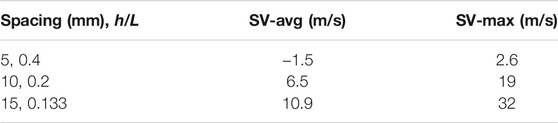
TABLE 5. Variation of swirl velocity on surface 4 with rib spacing.
Based on Tables 4 and 5, the nondimensional averaged and maximum swirl velocity (the ratio of swirl velocity to inlet swirl velocity) on the plane of surface 4 can be plotted against the height-to-spacing ratio h/L of the ribs, as shown in Figures 17 and 18, and for an inlet swirl velocity of 150 m/s. Results show that as well as rib angle, h/L can be identified as a key dimensionless parameter in controlling the flow approaching the seal. The larger the ratio was, the better the reduction of the swirl flow was. In summary, the geometric parameters of the ribs giving the most effective reduction in inlet swirl are α = 20°, h/L = 0.4 (h = 2 mm and L = 5 mm). For this geometry, swirl velocity is significantly reduced or negated as it passes through the separated flow region between the ribs, and a reasonably uniform radial inflow from this region supplies the seal leakage flow.
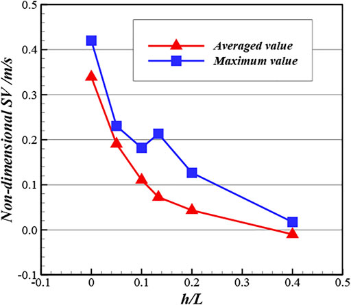
FIGURE 17. Swirl velocity on surface 4 against h/L of ribs.
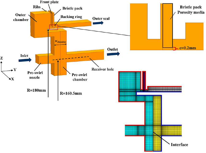
FIGURE 18. CFD domain and mesh for the preswirl chamber.
Preswirl Chamber Application
Computational Model
To further evaluate the use of ribs to reduce swirl velocity, an aeroengine preswirled cooling air delivery chamber was modeled incorporating a brush seal with a ribbed front plate in a modified outer seal position. The model geometry was based on an engine representative preswirl system (Chew et al., 2003; Liu G. et al., 2021; Liu Y. et al., 2021), with the introduction of an outer chamber, and is shown in Figure 18. To accommodate the selected design of ribs, circumferential periodicity was assumed for a 2.371° sector. The preswirl nozzles and receiver holes were modeled as slots, inner seal flow was set to zero, and the outer seal was modeled as a brush seal using the porous model with and without front plate ribs. The mid-radial location of preswirl nozzles and receiver holes is 160.5 mm. The radial extent and the axial width (wchamber) of the chamber are 28 and 8 mm, respectively. The brush seal geometry and initial choice of porosity were the same as those in the parametric study, as given in Table 1. It should be noted that, in this application, the seals are generally designed with a clearance due to the high shaft speeds, to mitigate the risk of heat generation or thermal runaway. Thus, a 0.2-mm radial clearance between rotor and the bristle pack was introduced. The selected front plate design had ribs inclined at 20° to the radial direction, with a height of 2 mm and spacing of 5 mm (h/L = 0.4). The red boundaries in Figure 18 represent stationary walls, and the blue boundaries represent the rotating walls. The stationary and rotating domains were generated separately and connected by an interface boundary. All domains were meshed by structure meshes, and relatively finer mesh was used for the bristle pack as well as the wall adjacent zones. The mesh had 3.5 million cells with near-wall spacing giving y + values in the range 30–80.
The turbulence characteristics of the flow were modeled using the standard k-ε equations with wall functions on the no-slip boundaries. As for the operating conditions, the total pressure 0.8 MPa was imposed on the preswirl nozzle inlet with swirl velocity 150 m/s, which gives a swirl ratio at nozzle exit around unity. The static pressure at the receiver hole outlet and outer seal outlet was 0.4 MPa, and the rotational speed of the rotating walls and rotational domain was 9,000 rpm (170 m/s at the seal radius) for all simulations. Calculations were considered converged when residuals of continuity, energy and turbulence equations reached 10−5, and the representative flow variables did not change with further iterations.
Results Analysis
Figure 19 shows swirl velocity contours on the periodic plane for the preswirl chamber solutions with and without ribs. Here, the most effective rib design from the parametric study is adopted, and the seal has a 0.2-mm clearance between the bristle pack and the rotor. The ribs on the upstream face of the front plate have little influence on the flow in the preswirl cavity and the swirl at the main cooling flow receiver hole, but clearly modify the flow as it approaches the seal. A further interesting point is that, even without the ribs fitted, the introduction of an outer chamber with stationary walls is effective in reducing swirl of the sealing flow. As confirmed by swirl velocity contours and streamlines just upstream of the seal in Figure 20, the ribs substantially reduce the swirl. It can be observed that the flow pattern for the ribbed case is similar to that in Figure 15A but with higher swirl beneath the bristle tips that suppresses the vortices shown in Figure 15. Effects of the shaft rotation, which were neglected in the parametric study, are seen to be confined to a very thin boundary layer. The average swirl velocity at surface 4 (0.2 mm upstream of the bristle pack) is reduced from 85.2 to 5.4 m/s. Therefore, the circumferential aerodynamic forces loading on the bristles, which scale with swirl dynamic head, will be reduced by a factor of approximately 250.
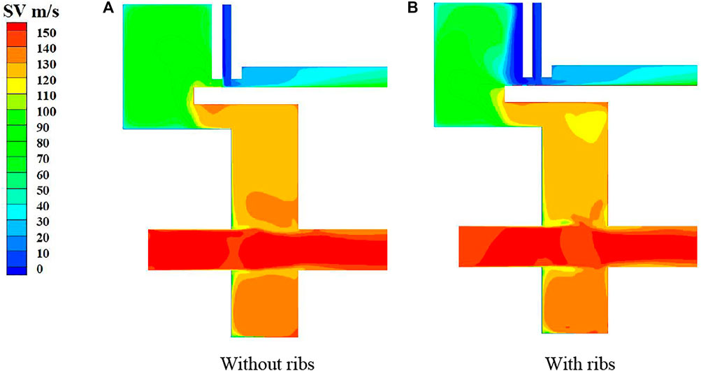
FIGURE 19. Swirl velocity contours on periodic surface for preswirl chamber applications: (A) without ribs, (B) with ribs.
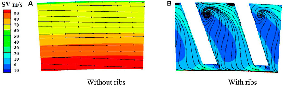
FIGURE 20. Swirl velocity contours and streamlines on surface 3 for preswirl chamber applications: (A) without ribs, (B) with ribs.
Further simulations were carried out for a wide range of leakage flow rates (varying porosity and clearance) and at a higher inlet swirl. The results are summarized in Table 6. This shows that the ribbed design could reduce the swirl significantly when leakage as a percentage of total supplied flow ranges from 0.35% to 5%. With higher inlet swirl velocity (250 m/s), the effect of ribs is still dramatic, reducing the swirl for surface 4 from 158.6 to 3.2 m/s. The data indicate that the effectiveness of the optimized geometry from the parametric study is sensitive to levels of inlet swirl and leakage flow but provides significant swirl reductions in all cases. Thus, inclusion of these parameters in rib optimization studies may give further performance improvements. Considering the maximum swirl velocity at surface 4 for r > 180.02 mm (excluding the velocity in the thin boundary on the rotating wall), it can be seen that reasonably uniform flow upstream the bristle pack is achieved. This is further illustrated by the contour plots in Figure 21.
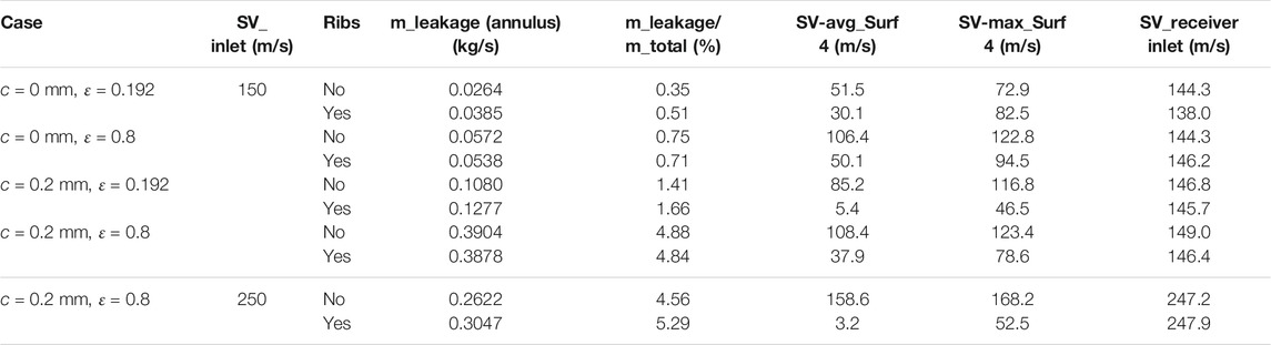
TABLE 6. Summary of results for all the conditions considered for the preswirl chamber.
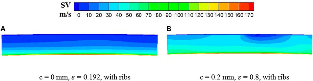
FIGURE 21. Swirl velocity contours approaching the seal for the lowest and highest leakage flow cases with ribbed front plates (SV = 150 m/s): (A) c = 0 mm, ε = 0.192, with ribs, (B) c = 0.2 mm, ε = 0.8, with ribs.
The moments on the rotor and stator and the swirl velocity of the blade cooling flow at the receiver affect the system performance. As might be expected, the ribs generally increase the moments slightly. As shown in Table 6, the effect on the main cooling air is limited so that an overall benefit from the reduced leakage using brush seals can be maintained.
Conclusion
A new design of brush seal front plate has been proposed and analyzed. The plate incorporates ribs that condition the flow entering the bristle pack reducing the flow swirl and hence protect the bristle from destabilizing aerodynamic forces. The main conclusions are summarized as follows.
1. Angled ribs on the upstream side of the front plate can effectively condition the flow upstream of the bristle pack, reducing swirl and deflecting the flow to feed the seal. This will reduce the circumferential forces impacting on the bristle pack, thereby controlling the bristle slip and instability.
2. Positive rib angles with the flow deflected radially inward toward the seal are clearly more effective in reducing swirl near the shaft and seal inlet. As the positive rib angle increases, the swirl velocity beneath the rib tip is seen to also increase. This could lead to destabilizing aerodynamic forces on the bristles in this region, and the best angle for reducing the swirl flow velocity was found to be approximately 20°.
3. The height-to-spacing ratio of the ribs is another key parameter in controlling the flow approaching the seal. At a rib angle of 20°, ratios ranging from 0 (no ribs) to 0.4 were studied, and the larger the ratio was, the better the reduction of the swirl flow and induction of radial inflow was. Ribs inclined at 20° to the radial direction, with height-to-spacing ratio of 0.4 (height of 2 mm and spacing of 5 mm), showed the best performance in reducing swirl and the most uniform flow in the channel between the ribs.
4. Evaluating the selected design in a CFD model of a turbine cooling preswirl chamber confirmed the expected performance. A number of operating conditions were considered to test the design. In these tests, the leakage flow rate varied from 0.35% to 5% of the supplied coolant flow rate, and the inlet swirl ranged from 150 to 250 m/s. The ribs were found to perform well in reducing swirl (which is expected to improve the seal stability), while having little effect on the preswirl delivery air. Considering the observed reduction in inlet swirl due to the introduction of a seal outer chamber and sensitivities to inlet swirl and leakage rates, inlet swirl reduction might be further improved with additional optimization of the rib and cavity geometry. While the preswirl chamber has provided a useful test case, this sealing geometry can be deployed in other high-value sealing positions where inlet swirl immediately incident on the upstream cover plate region could potentially destabilize the bristle pack.
Data Availability Statement
The raw data supporting the conclusion of this article will be made available by the authors, without undue reservation.
Author Contributions
LY, CJ, and PM provide research idea and formal analysis. DW and YB carried out all the calculation work. LY and DW write the original manuscript. CJ, PM, and KX are responsible for the revision of the paper. All authors have read and agreed to the published version of the manuscript.
Funding
This research is supported by the National Natural Science Foundation of China (No. 52106040, No. 52006021), China Postdoctoral Science Foundation (No. 2021M700648, No. 2021M690498), Dalian Science and Technology Innovation Fund (No. 2021JJ12GX030) and Natural Science Foundation of Liaoning Province (No. 2020-BS-069).
Conflict of Interest
The authors declare that the research was conducted in the absence of any commercial or financial relationships that could be construed as a potential conflict of interest.
Publisher’s Note
All claims expressed in this article are solely those of the authors and do not necessarily represent those of their affiliated organizations, or those of the publisher, the editors and the reviewers. Any product that may be evaluated in this article, or claim that may be made by its manufacturer, is not guaranteed or endorsed by the publisher.
References
Aslan-zada, F. E., Mammadov, V. A., and Dohnal, F. (2013). Brush Seals and Labyrinth Seals in Gas Turbine Applications. Proc. Inst. Mech. Eng. A: J. Power Energ. 227 (2), 216–230. doi:10.1177/0957650912464922
Asok, S. P., Sankaranarayanasamy, K., Sundararajan, T., Starwin, P., Kalieswaran, R., and Dinesh, M. (2008). Pressure Drop Characteristics of Water Flow through Static Annular and Triangular Cavity Labyrinth Seals. Eng. Appl. Comput. Fluid Mech. 2 (4), 482–495. doi:10.1080/19942060.2008.11015246
Bayley, F. J., and Long, C. A. (1993). A Combined Experimental and Theoretical Study of Flow and Pressure Distributions in a brush Seal. J. Eng. Gas Turbines Power 115 (2), 404–410. doi:10.1115/1.2906723
Chew, J., Hills, N., and Khalatov, S. (2003). “Measurement and Analysis of Flow in a Pre-swirled Cooling Air Delivery System,” in ASME Turbo Expo 2003: Power for Land, Sea, and Air (Atlanta, GA: ASME), 3. doi:10.1115/gt2003-38084
Chew, J. W., and Hogg, S. I. (1997). Porosity Modeling of brush Seals. J. Tribology 119 (4), 769–775. doi:10.1115/1.2833883
Chew, J. W., Lapworth, B. L., and Millener, P. J. (1995). Mathematical Modeling of brush Seals. Int. J. Heat Fluid Flow 16 (6), 493–500. doi:10.1016/0142-727X(95)00061-T
Chupp, R. E., Ghasripoor, F., Turnquist, N. A., Demiroglu, M., and Aksit, M. F. (2002). Advanced Seals for Industrial Turbine Applications: Dynamic Seal Development. J. Propulsion Power 18 (6), 1260–1266. doi:10.2514/2.6061
Crudgington, P., Bowsher, A., Kirk, T., and Walia, J. (2012). “Brush Seal Hysteresis,” in 48th AIAA/ASME/SAE/ASEE Joint Propulsion Conference & Exhibit (Atlanta: AIAA). doi:10.2514/6.2012-4003
Dogu, Y., and Aksit, M. F. (2006). Effects of Geometry on Brush Seal Pressure and Flow Fields-Part I: Front Plate Configurations. J. Turbomach. 128 (2), 367–378. doi:10.1115/1.2101857
Dogu, Y., Bahar, A. S., and Sertcakan, M. C. (2016). Computational Fluid Dynamics Investigation of brush Seal Leakage Performance Depending on Geometric Dimensions and Operating Conditions. J. Eng. Gas Turbines Power 138 (3), 1–13. doi:10.1115/1.403137010.1115/1.4031370
Gresham, T. G., Weaver, B. K., Wood, H. G., and Untaroiu, A. (2016). “Characterization of Brush Seal Permeability,” in ASME Turbo Expo 2016: Power for Land, Sea, and Air (Seoul, South Korea: ASME), 3. doi:10.1115/GT2016-57910
Guardino, C., and Chew, J. W. (2004). “Numerical Simulation of 3D Bristle Bending in Brush Seals,” in ASME Turbo Expo 2004: Power for Land, Sea, and Air (Vienna, Austria: ASME), 3. doi:10.1115/GT2004-53176
Helm, P., Pugachev, A., and Neef, M. (2008). “Breaking the Swirl with Brush Seals: Numerical Modeling and Experimental Evidence,” in ASME Turbo Expo 2008: Power for Land, Sea, and Air (Berlin, Germany: ASME), 3. doi:10.1115/gt2008-50257
Lelli, D., Chew, J. W., and Cooper, P. (2006). Combined Three-Dimensional Fluid Dynamics and Mechanical Modeling of Brush Seals. J. Turbomach. 128 (1), 188–195. doi:10.1115/1.2103093
Liu, G., Gong, W., Wu, H., and Lin, A. (2021). Experimental and CFD Analysis on the Pressure Ratio and Entropy Increment in a Cover-Plate Pre-swirl System of Gas Turbine Engine. Eng. Appl. Comput. Fluid Mech. 15 (1), 476–489. doi:10.1080/19942060.2021.1884600
Liu, Y., Chew, J. W., Pekris, J., Pekris, M. J., and Kong, X. (2020). The Effect of Inlet Swirl on Brush Seal Bristle Deflections and Stability. J. Eng. Gas Turbines Power 142 (7), 071002. doi:10.1115/1.4046696
Liu, Y., Yue, B., Kong, X., Chen, H., and Lu, H. (2021). Design and Performance Analysis of a Vane Shaped Rotating Receiver Hole in High Radius Pre-swirl Systems for Gas Turbine Cooling. Aerospace Sci. Tech. 115 (2021), 106807. doi:10.1016/j.ast.2021.106807
Pugachev, A. O. (2014). “Aggregation of Experimental and Theoretical Data for brush Seal Leakage Evaluation,” in 50th AIAA/ASME/SAE/ASEE Joint Propulsion Conference (Cleveland, OH: AIAA). doi:10.2514/6.2014-3598
Ramakrishna, P. V., and Govardhan, M. (2009). Aerodynamic Performance of Low Speed Axial Flow Compressor Rotors with Sweep and Tip Clearance. Eng. Appl. Comput. Fluid Mech. 3 (2), 195–206. doi:10.1080/19942060.2009.11015265
Sharatchandra, M. C., and Rhode, D. L. (1996). Computed Effects of Rotor-Induced Swirl on Brush Seal Performance-Part 2: Bristle Force Analysis. J. Tribology 118 (4), 920–926. doi:10.1115/1.2831629
Sun, D., Liu, N.-N., Fei, C.-W., Hu, G.-Y., Ai, Y.-T., and Choy, Y.-S. (2016). Theoretical and Numerical Investigation on the Leakage Characteristics of Brush Seals Based on Fluid-Structure Interaction. Aerospace Sci. Tech. 58, 207–216. doi:10.1016/j.ast.2016.08.023
Turner, M. T., Chew, J. W., and Long, C. A. (1998). Experimental Investigation and Mathematical Modeling of Clearance Brush Seals. J. Eng. Gas Turbines Power 120, 573–579. doi:10.1115/1.2818185
Wei, Y., Chen, Z., and Jiao, Y. (2015). Effects of Geometry on Leakage Flow Characteristics of Brush Seal. J. Harbin Inst. Tech. 22 (002), 1–7. doi:10.11916/j.issn.1005-9113.2015.02.001
Zhang, Y., Yan, J., and Li, J. (2017). Investigations on Leakage Flow Characteristics of Brush Seal with Consideration of Blow Down Effect. Lubrication Eng. 42 (4), 36–42. doi:10.3969/j.issn.0254-0150.2017.04.007
Zhao, H., and Stango, R. J. (2007). Role of Distributed Interbristle Friction Force on Brush Seal Hysteresis. J. Tribology 129 (1), 199–204. doi:10.1115/1.2401218
Nomenclature
a Viscous resistance coefficient
b Inertial resistance coefficient
D Bristle diameter, m
H Height of bristle overhang, m
h Rib height, m
L Rib spacing, m
Lb Bristle length, m
N Density of the bristles, bristles/mm
p* Nondimensional pressure = (p − pout)/(pin − pout)
R Radial location, m
SV Swirl velocity, m/s
w Ribs width, m
wb Thickness of the bristle pack, m
X, Y, Z Circumferential, axial, radial direction, respectively
Zrotor Radial clearance between bristle and rotor, m
α Incline angle of ribs, °
δ Minimum clearance between bristles, m
ε Porosity of the bristle pack
ρ Density of the flow, kg/m3
ϕ Incline angle of bristle pack, °
Subscripts
m Parallel to the bristles
n Perpendicular to the bristles
z Parallel to the rotating shaft
Keywords: brush seal, inlet swirl, front plate, ribs, bristle stability
Citation: Liu Y, Dong W, Chew J, Pekris M, Yue B and Kong X (2022) Flow Conditioning to Control the Effects of Inlet Swirl on Brush Seal Performance in Gas Turbine Engines. Front. Energy Res. 9:815152. doi: 10.3389/fenrg.2021.815152
Received: 15 November 2021; Accepted: 02 December 2021;
Published: 03 February 2022.
Edited by:
Lei Luo, Harbin Institute of Technology, ChinaReviewed by:
Shuang Guo, Dalian University of Technology, ChinaGaowen Liu, Northwestern Polytechnical University, China
Copyright © 2022 Liu, Dong, Chew, Pekris, Yue and Kong. This is an open-access article distributed under the terms of the Creative Commons Attribution License (CC BY). The use, distribution or reproduction in other forums is permitted, provided the original author(s) and the copyright owner(s) are credited and that the original publication in this journal is cited, in accordance with accepted academic practice. No use, distribution or reproduction is permitted which does not comply with these terms.
*Correspondence: Yuxin Liu, yxliu@dlmu.edu.cn