Unified Active and Reactive Power Coordinated Optimization for Unbalanced Distribution Networks in Radial and Looped Topology
 Yuanjing Zeng1*
  Peishuai Li
- 1Industrial Center, Nanjing Institute of Technology, Nanjign, China
- 2Economic Research Institution, State Grid Jiangsu Electric Power Co., Ltd., Nanjign, China
- 3School of Automation, Nanjing University of Science and Technology, Nanjing, China
Facing the high proportion of distributed generations incorporating in a single phase, the active distribution network has become more unbalanced with flexible topology. In this paper, a unified active and reactive power coordinated optimization (ARPCO) method, which is applicable in both radial and looped unbalanced distribution networks, is proposed. Aiming to reduce power losses and restrain undervoltage and overvoltage problems, the ARPCO model which regulates the active and reactive power output of distributed generations coordinately and optimally is constructed. A novel trust region sequential linear programming (SLP) method, which is effective in nonlinear and nonconvex model solving, is developed and employed in APRCO model solution. A multi-scenario case study based on the modified IEEE 123 node distribution system shows that the proposed method is able to reduce the system active power loss and solve undervoltage and overvoltage problems efficiently, at the same time maximizing the utilization of distributed generations.
1 Introduction
With construction of low-carbon energy systems, the penetration of distributed generations (DGs) in distribution networks (DNs) has been growing rapidly (D'Adamo et al., 2009). The large amounts of grid-connected DGs have been changing the voltage level and power flow distribution of the DN (Wu et al., 2017) evidently; especially, the frequent power variation of DGs may cause voltage fluctuation and overvoltage and undervoltage problems, even sacrificing power quality. Under the worst conditions, it may lead up to the DGs out of service and destruction of electric equipment, which is a severe waste of renewable energy and power grid assets (Tonkoski et al., 2012; Eftekharnejad et al., 2013; Gao et al., 2018; Zhang et al., 2019). On the other hand, the integrated inverter-based DGs are excellent active and reactive power supply resources with a fast response speed; thus, it promotes the controllability and optimal operation potential of DN significantly (Li et al., 2018).
Generally, the reasonable reactive power optimization can restrain supply voltage fluctuation introduced by DGs and reduce active power loss of DN. In Chen et al. (2015), a centralized reactive power optimization method designed for low-voltage DN is proposed to reduce power losses. In Daratha et al. (2014) and Wang et al. (2014), volt/var optimization of DN is implemented by comprehensive regulation of on-load tap changers (OLTCs), static var compensators (SVCs), and CBs. In Tonkoski et al. (2011) and Lemkens et al. (2013), the photovoltaic (PV) active power curtailment strategy based on voltage droop is proposed to restrain the overvoltage problem. Although the DN safe operation is ensured, the renewable energy power is wasted. Actually, the typical DGs, for example, PVs, are installed in DN with inverters, of which the active and reactive power can be controlled separately. In addition, in Barr and Majumder (2014), grid voltage feedback is introduced into the reactive power control loop of the DG inverter to limit the voltage rise of point of common coupling (PCC) by real-time adjustment of DG reactive power output. However, voltage is regulated locally by this method and voltage qualification of the whole network cannot be guaranteed. Calderaro et al. (2014) proposes a DN voltage control method with the objective of minimizing the reactive power output of DGs, and the DN voltage is regulated with relatively small occupation of DG capacity. Li et al. (2020) further considers the coordination of PV reactive power output and OLTC. It has been widely known that the remaining capacity of DGs can be high-quality reactive power sources to provide auxiliary services as voltage regulation, power losses, and so forth. In Farivar et al. (2012), a second-order cone programming (SOCP)-based inverter varoptimization model is established to reduce DN active power losses within the bus voltage limitations, and Zheng et al. (2016) develop an alternating direction method of multipliers based on the full distributed algorithm to solve the proposed SOC model.
The above research studies are all based on balanced network assumption; however, the low-voltage DN is always unbalanced due to the fact that the load unbalance, line parameter asymmetry, and open-phase operation are ubiquitous (Omar and Rahim, 2012; Kekatos et al., 2016). Moreover, rooftop PVs and electrical vehicles aggravate unbalance in low-voltage DN (Kamh and Iravani, 2010; Yan and Saha, 2012). Therefore, the three balanced assumptions will introduce large errors in DN operation, and adopting the multi-phase model in the unbalanced system has been widely accepted (Kamh and Iravani, 2010; Wang et al., 2015). In Daratha et al. (2014), a coordinated optimization model is developed for unbalanced DN, which coordinates OLTC, CBs, and reactive output of DGs to control DN bus voltage and reduce active power loss. In addition, Mostafa et al. (2013) proposed a multi-objective optimization method for operating DN co-operating a large number of single-phase solar generators, and the current unbalance and energy loss are minimized via reactive compensation devices and reconfiguration switches. Moreover, both the bus active and reactive power injection impact the bus voltage significantly due to the high R/X ration in DN. It is complex that the active power and reactive power output of DGs are coupled tightly, which may need other measures when the inverter active power is high and the inverter remaining capacity cannot compensate overvoltage adequately. Consequently, Kulmala et al. (2014) present a sensitivity-based active and reactive power coordinated control algorithm. In the case of overvoltage, reactive power control should be carried out preferentially. If the reactive power control method cannot restore the bus voltage, the active power control is implemented, which usually includes DG active power output curtailment. However, in the aforementioned method, the active and reactive powers are controlled individually, which is not consistent with the fact that DG active and reactive powers are highly coupled.
To fill the research gaps shown as above, a unified active and reactive power coordinated optimization (ARPCO) method is proposed for unbalanced DN incorporating distributed grid-connected PV generations. The proposed method coordinates active and reactive output powers of PVs via the constructed optimization model, which could maximize the active power output of PVs as well as minimize active power loss on the premise of supply voltage qualification under various operation statuses of DN. Moreover, the proposed ARPCO is highly applicable in both radial and looped topologies.
The main contributions of this paper are described as follows:
(1) With consideration of high coupling between active and reactive power outputs of DGs, the ARPCO model which is unified in radial and looped topologies is established to maximize the unitization of DGs and minimize active power loss of DN.
(2) A trust region sequential linear programming (SLP) algorithm is proposed to solve the ARPCO model effectively. The proposed SLP is effective in nonconvex and nonlinear model solving, while its accuracy and convergence speed are improved evidently compared with the existing fixed step-size SLP.
The rest of the paper is organized as follows: Section 2 presents the established ARPCO model. In Section 3, the trusted region SLP algorithm is illustrated detailedly in the ARPCO model solution. The multi-scenario case study based on modified IEEE 123 node unbalanced DN is described in Section 4, which validates the proposed method. Section 5 concludes this paper.
2 Coordinated Optimization Model
2.1 Objective Functions
The main objectives of this study are as follows:
— To minimize active power loss of the unbalanced radial and looped DN.
— To maximize active power utilization of the grid-connected DGs.
For an unbalanced DN with N nodes, the active power loss equals the sum of active power injections of all nodes including the slack bus or substation bus
where
The second objective is to maximal utilization of DG’s active power, and all the DGs’ active power output is summed as
where
Whole injection of each node can be described as
where
Combing Eqs 1, 2, the objective function is determined by
where node 1 is the slack bus.
In Eq. 4, load data are given and fixed. Therefore, minimizing
2.2 Constraints
In the coordinated optimization model, the state variable, voltage of each node, and the control variable, active and reactive power output of the grid-connected DGs, must satisfy the following constraints:
where Eq. 6 is the power flow equation for an unbalanced system;
The feasible region of a DG generated by Constraints 8, 9 is shown as the shadow in Figure 1A. In this study, the nonlinear constraint of DG is linearized by approximating arcs

FIGURE 1. Active and reactive power feasible region of DG.
Then, the shadow in Figure 1B, namely, the feasible region of each DG, can be described by four linear constraints:
where
To sum up, the coordinated optimization model is achieved by
3 Trust Region SLP Method
The proposed ARPCO model is a nonlinear and nonconvex program due to the power balance Constraints 7. In recent papers, many heuristic algorithms based on artificial intelligence have been proposed to find good solutions to the optimization problem, such as the genetic algorithm (Moradi and Abedini, 2012), differential evolution (Basu, 2016), particle swarm optimization (Gomez-Gonzalez et al., 2012; Schweickardt et al., 2016), and so forth. Moreover, the effective mathematical methods such as SLP (Olofsson et al., 1995; Mohapatra et al., 2013) and successive quadratic programing (SQP) (Palma-Behnke et al., 2004) are also proposed. However, artificial intelligence heuristic algorithms do not guarantee an optimal solution and are unreliable for practical applications. As for the SLP and SQP, they suffer from choosing an appropriate step size; for example, the small step size usually leads to slow convergence and the large step size decreases the convergence accuracy. Thus, in this paper, a trust region SLP method is proposed to achieve both a fast convergence speed and high accuracy by designing a self-adaptive step size.
3.1 Trust Region Technology
Trust region methods are a class of numerical methods for optimization, which compute a trial step by solving a trust region subproblem (Yuan, 2015). To be more specific, for a general optimization problem
where
At the kth iteration, a trust region algorithm obtains a trial step dk by solving the following trust region subproblem:
where mk(d) is a model function that approximates the objective function f(xk + d) near the current iteration point xk, Xk is an approximation to the feasible set, ||∙||Wk is a norm, and
3.2 Linear Approximation
One of the essential parts of trust region methods is the choice of trust region subproblem. Linear programing (LP) has been proved efficient by many scholars; thus, LP is combined with the trust region algorithm in this paper.
Assuming that (u0, x0) is a certain operation status of unbalanced DN, the linear approximation of the ARPCO model can be described as
where
Therefore, at the kth iteration, the LP-based trust region subproblem of (14) is
where subscript k represents the value of the kth iteration,
3.3 Trust Region Radius
The essential part of the trust region algorithm is to determine an appropriate trust region radius during each iteration. At the kth iteration, let dk be a trial step which solves the trust region subproblem (15). Then, the predicted reduction of the original optimization model (14) is computed by
and the actual reduction of (15) is
The ratio is defined by
Then, the trust region radius of the next iteration is determined by
It is proven in Powell and Yuan, 1990 that the trust region method features global convergence and local superlinear convergence.
The actual implementation of the proposed trust region SLP method is summarized as below:
Step 1 Initialization.
• Set the iteration counter k = 1;
• Initialize error bound err1 and err2, trust region radius
• Initialize control variables
Step 2 Solve the trust region subproblem.
• Generate the LP-based trust region subproblem (17);
• Solve LP (17) and acquire
• Calculate
Step 3 Check convergence.
• Calculate the initial operation point of the next iteration:
• If both
• Solve the power flow Eq.6 with
• Increase the iteration counter by k = k+1, then jump to Step 2.
Step 4 Acquire the optimal solutions.
• Solve the power flow Eq. 6 with
4 Case Study
In order to verify the effectiveness of proposed ARPCO method for unbalanced DN, the case study is implemented on the modified IEEE 123 node unbalanced test feeder (Feeders, 1991) employing the MATLAB software. A Newton–Raphson power flow solver is developed, and the LP-based subproblem is modeled and solved in YALMIP (Lofberg, 2004) by the Cplex solver. The hardware environment is Intel i5 @ 3.3 GHz CPU with 4 GB RAM. The OS is win7 64 bit, the MATLAB version is R2015a, the YALMIP version is 20150204, and the Cplex version is 12.6.
4.1 The Modified IEEE 123 Node Test Feeder
The IEEE 123 node unbalanced distribution test feeder is used and modified by installing several distributed PVs, as is shown in Figure 2.
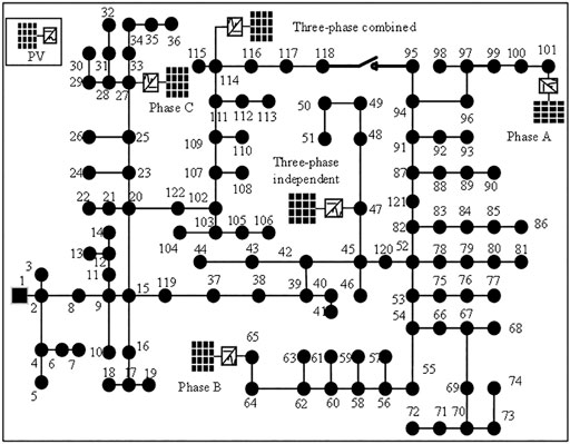
FIGURE 2. Diagram of the modified IEEE 123 nodes test feeder.
The voltage level of the test system is 4.16 kV, and the slack bus (node 1) voltage is set as 1.05 p.u. The total active load is 3,490 kW, while the total reactive load is 1,925 kVar. Due to large load difference up to hundreds of kilowatts among different phases and asymmetric line parameters, the three-phase unbalance is severe in this system. Moreover, it has many zero self-impedance as well as zero mutual-impedance branches and single-phase or two-phase branches; thus, its numerical conditions are very complex.
In the test system, three single-phase PVs whose capacity is 500 kVA are connected to node 27 phase C (PV 27), node 65 phase B (PV 65), and node 101 phase A (PV 101), respectively. Then, two three-phase PVs are installed at node 47 (PV47) and node 114 (PV114), while the capacity of each phase PV is 600 kVA. PV114 is three-phase combined, and the output power of each phase can just be controlled simultaneously. PV47 is three-phase-independent, and the output power of each phase can be controlled independently.
In this study, three typical scenarios are designed with a secure voltage range of all nodes set from 0.95 p.u. to 1.05 p.u. and the reactive power output limitation coefficient α set on 0.5.
4.2 Optimal Reactive Power Allocation for Loss Reduction
In scenario 1, all the PVs operate at the forecasted maximum active power point without the reactive power output before optimization, while all the PVs keep tracking the forecasted maximum active power point with the reactive power output instructed by the proposed strategy after optimization, as is shown in Table 1.
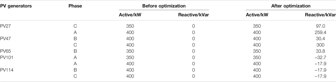
TABLE 1. Comparison of active and reactive power outputs before and after optimization.
Through this study, DGs like PV should undertake more responsibility for the system optimization, such as voltage regulation and loss reduction. Due to three-phase unbalance, the reactive power output differs among three phases, such as PV47, which is more accurate. The active power loss comparison before and after optimization is shown in Table 2.
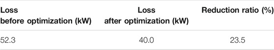
TABLE 2. Comparison of active power losses before and after optimization.
Usually, PV inverters own considerable remaining capability, which can be used as reactive compensators if optimal allocated for loss reduction.
4.3 Voltage Support Under a Heavy Load
In scenario 2, the active power outputs of PVs are set as 0, which shows that the phenomenon occurs during night or cloudy days. The active and reactive load is enlarged by 1.3 times considering load increase in the future. Consequently, severe undervoltage problems would happen. By the ARPCO method, PV inverters are used as reactive compensators to support the system voltage, guaranteeing supply voltage security, as is shown in Figure 3.
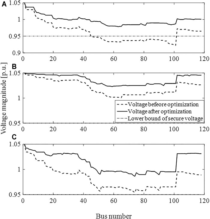
FIGURE 3. Voltage magnitude comparison between before and after optimization: (A) phase A, (B) phase B and (C) phase C.
It can be seen that the voltage magnitude from bus 52 to bus 101 in phase A exceeds the lower voltage secure bound before optimization. In comparison, the voltage magnitude of the whole system is lifted and the voltage of all buses and all phases is kept within the system secure voltage limitation with application of ARPCO. What is more, the voltage rise degree of different phases differs from each other because detailed unbalanced models are adopted and all PVs except PV114 could be controlled in the single phase. As a result, unbalanced reactive power compensation schemes are adopted according to the actual situation of each phase and voltage unbalance is alleviated.
The active power losses are also reduced in this scenario. The relationship between the active power loss and maximum reactive compensation capability of each PV inverter quantified by coefficient α is studied, as is shown in Table 3.
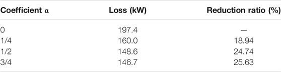
TABLE 3. Relationship between active power loss and maximum reactive compensation capability.
From Table 3, it can be concluded that the bigger reactive compensation capability usually brings bigger active power loss reduction. However, when the system reactive power reserve is adequate, the active power loss improvement is inconspicuous with the increase of reactive power compensation capability. For example, the active power loss decreases only 2.1 kW when the maximum reactive power compensation capability increases from 1/2 of PV capability to 3/4 of PV capability. Therefore, the present load demand, future load increase, and reactive power compensation demand should be taken into comprehensive consideration when determining optimal installation capability of DGs at the planning stage. Also, in this study, reactive power is considered as “free;” thus a more accurate model which quantifies “the price of reactive power” should be included in future work.
4.4 Maximize Active Power Output of DGs When Overvoltage Occurs
In scenario 3, the maximum active power output equals the installation capability for each PV, which generally occurs at noon. If all the PVs keep on the MPPT mode, the inverters retain no reactive power supply and severe overvoltage happens due to voltage rise caused by high power injection of PVs. To keep DN secure, either certain voltage regulators should be installed, such as OLTC, CBs, and SVCs, or the active output of the PVs should be curtailed. By the proposed APRCO, the active power output of the PVs is maximized, that is, PV curtailment is minimized, to limit the voltage magnitude within the allowable range, needless for extra devices.
As is shown in Figure 4, severe overvoltage happens especially in phase B due to PV power injection. Employing the ARPCO, the voltages of all buses are regulated within the allowable range. Moreover, the voltage unbalance is alleviated, while the voltage in phases A and B drops with the voltage in phase C rises slightly. This is because the ARPCO model is constructed with consideration of high coupling between the three phases.
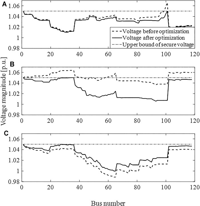
FIGURE 4. Voltage magnitude comparison between before and after optimization: (A) phase A, (B) phase B and (C) phase C.
As the active power and reactive power output of PVs are optimized simultaneously, there is more PV active power absorbed by DN than the active power curtailment method, as shown in Table 4.
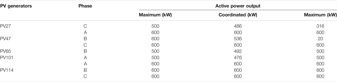
TABLE 4. Active power output comparison among different strategies.
As shown in Table 4, PV27 needs to curtail 14 kW, PV47 needs to curtail 64 kW, PV 65 needs to curtail 8 kW, and PV101 needs to curtail 24 kW by APRCO. In contrast, at least 764 kW needs to be curtailed if only the active power curtailment method is employed. Then, there are about 7 times renewable energy source waste in the traditional active power curtailment method compared to APRCO.
4.5 Computational Performance Analysis
To validate effectiveness of the proposed trust region SLP method, computational analysis is done toward the proposed trust region SLP and two basic SLP methods with fixed step sizes of 0.001 and 0.0002 apparently in the aforementioned three scenarios. The convergence accuracy is set on err1 = 10-6 and err2 = 2 × 10⁻³ apparently. The result is given in Table 5.
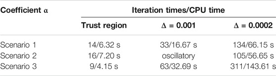
TABLE 5. Relationship between active power loss and maximum reactive compensation capability.
The proposed trust region SLP method performs better in terms of both convergence speed and convergence accuracy. This is because the self-adaptive step size overcomes the conflict between speed and accuracy. When the fixed step size is adopted, either the convergence speed or the convergence accuracy is low. For example, a step size of 0.001 convergences much faster than 0.0002, while it fails to converge in scenario 2. Also, the convergence progress of scenario 2 by different methods is analyzed in Figure 5.
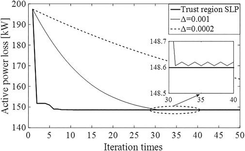
FIGURE 5. Active power loss variation in scenario 2.
It can be inferred from Figure 5 that trust region SLP converges much faster than the two SLPs with a fixed step size. When choosing Δ = 0.0002, it still has not converged after 50 iterations, while it starts to oscillate after about 30 iterations when choosing Δ = 0.001.
5 Conclusion
In order to fulfill the demand of operating radial and looped unbalanced DN with increasing penetration of DGs, a unified ARPCO model is established and a trust region SLP method is proposed to solve the constructed nonlinear and nonconvex models in this paper. The multi-scenario case study based on the modified IEEE 123 node test feeder shows that (1) active power loss could be reduced and overvoltage as well as undervoltage problems could be restrained by coordinated optimization of DGs’ active and reactive power output; thus, it increases the ability of DN absorbing DGs; (2) the proposed trust region SLP method preforms well in both aspects of convergence speed and computational accuracy, superior to the fixed step SLP method. Meanwhile, it can satisfy the online optimization requirement of unbalanced DN incorporating a large amount of DGs.
Data Availability Statement
The original contributions presented in the study are included in the article/supplementary material; further inquiries can be directed to the corresponding author.
Author Contributions
YZ: APRCO model construction, trust region SLP algorithm development, and writing the paper. YW: DG model construction and programming. PL: literature review and APRCO model construction.
Conflict of Interest
Author YW is employed by State Grid Jiangsu Electric Power Co., Ltd.
The remaining authors declare that the research was conducted in the absence of any commercial or financial relationships that could be construed as a potential conflict of interest.
Publisher’s Note
All claims expressed in this article are solely those of the authors and do not necessarily represent those of their affiliated organizations or those of the publisher, the editors, and the reviewers. Any product that may be evaluated in this article or claim that may be made by its manufacturer is not guaranteed or endorsed by the publisher.
References
Barr, J., and Majumder, R. (2014). Integration of Distributed Generation in the Volt/VAR Management System for Active Distribution Networks. IEEE Trans. Smart Grid 6 (2), 274–284. doi:10.1109/TSG.2014.2363051
Basu, M. (2016). Quasi-oppositional Differential Evolution for Optimal Reactive Power Dispatch. Int. J. Electr. Power Energ. Syst. 78, 29–40. doi:10.1016/j.ijepes.2015.11.067
Calderaro, V., Galdi, V., Lamberti, F., and Piccolo, A. (2014). A Smart Strategy for Voltage Control Ancillary Service in Distribution Networks. IEEE Trans. Power Syst. 30 (1), 494–502. doi:10.1109/TPWRS.2014.2326957
Chen, S. X., Foo, Y. S. E., Gooi, H. B., Wang, M. Q., and Lu, S. F. (2015). A Centralized Reactive Power Compensation System for LV Distribution Networks. IEEE Trans. Power Syst. 30 (1), 274–284. doi:10.1109/tpwrs.2014.2326520
D'Adamo, C., Jupe, S., and Abbey, C. (2009). “Global Survey on Planning and Operation of Active Distribution Networks-Update of CIGRE C6. 11 Working Group Activities,” in Proc. 20th Int. Conf. and Exhibition on Electricity Distribution: -Part 1, Prague, Czech, 8-11 June 2009, 1–4. doi:10.1049/cp.2009.0836
Daratha, N., Das, B., and Sharma, J. (2014). Coordination between OLTC and SVC for Voltage Regulation in Unbalanced Distribution System Distributed Generation. IEEE Trans. Power Syst. 29 (1), 289–299. doi:10.1109/tpwrs.2013.2280022
Eftekharnejad, S., Vittal, V., Heydt, G. T., Keel, B., and Loehr, J. (2013). Impact of Increased Penetration of Photovoltaic Generation on Power Systems. IEEE Trans. Power Syst. 28 (2), 893–901. doi:10.1109/tpwrs.2012.2216294
Farivar, M., Neal, R., and Clarke, C. (2012). “Optimal Inverter Var Control in Distribution Systems with High PV Penetration,” in IEEE Power and Energy Society General Meeting, San Diego, CA, USA, 22-26 July 2012, 1–7. doi:10.1109/PESGM.2012.6345736
Feeders, R. (1991). IEEE Distribution Planning Working Group Report. IEEE Trans. Power Syst. 6 (3), 975–985. 10.1109/59.119237.
Gao, H., Liu, J., and Wang, L. (2018). Robust Coordinated Optimization of Active and Reactive Power in Active Distribution Systems. IEEE Trans. Smart Grid 9 (5), 4436–4447. doi:10.1109/tsg.2017.2657782
Gomez-Gonzalez, M., López, A., and Jurado, F. (2012). Optimization of Distributed Generation Systems Using a New Discrete PSO and OPF. Electric Power Syst. Res. 84 (1), 174–180. doi:10.1016/j.epsr.2011.11.016
Kamh, M. Z., and Iravani, R. (2010). Unbalanced Model and Power-Flow Analysis of Microgrids and Active Distribution Systems. IEEE Trans. Power Deliv. 25 (4), 2851–2858. doi:10.1109/tpwrd.2010.2042825
Kekatos, V., Zhang, L., Giannakis, G. B., and Baldick, R. (2016). Voltage Regulation Algorithms for Multiphase Power Distribution Grids. IEEE Trans. Power Syst. 31 (5), 3913–3923. doi:10.1109/tpwrs.2015.2493520
Kulmala, A., Repo, S., and Jarventausta, P. (2014). Coordinated Voltage Control in Distribution Networks Including Several Distributed Energy Resources. IEEE Trans. Smart Grid 5 (4), 2010–2020. doi:10.1109/tsg.2014.2297971
Lemkens, K., Geth, F., Vingerhoets, P., and Deconinck, G. (2013). “Reducing Overvoltage Problems with Active Power Curtailment—Simulation Results,” in IEEE PES ISGT Europe 2013, Lyngby, Denmark, 6-9 Oct. 2013, 1–5. doi:10.1109/ISGTEurope.2013.6695298
Li, P., Wu, Z., Wang, Y., Dou, X., Hu, M., and Hu, J. (2018). Adaptive Robust Optimal Reactive Power Dispatch in Unbalanced Distribution Networks with High Penetration of Distributed Generation. IET Generation, Transm. Distribution 12 (6), 1382–1389. doi:10.1049/iet-gtd.2017.0674
Li, P., Zhang, C., Wu, Z., Xu, Y., Hu, M., and Dong, Z. (2020). Distributed Adaptive Robust Voltage/var Control with Network Partition in Active Distribution Networks. IEEE Trans. Smart Grid 11 (3), 2245–2256. doi:10.1109/tsg.2019.2950120
Lofberg, J. (2004). “YALMIP: 'A Toolbox for Modeling and Optimization in MATLAB',” in IEEE International Symptom Computer Aided Control Systems Design, Taipei, Taiwan, 2-4 Sept. 2004, 284–289. doi:10.1109/cacsd.2004.1393890
Mohapatra, A., Bijwe, P. R., and Panigrahi, B. K. (2013). Efficient Sequential Non‐linear Optimal Power Flow Approach Using Incremental Variables. IET Generation, Transm. Distribution 7 (12), 1473–1480. doi:10.1049/iet-gtd.2012.0750
Moradi, M. H., and Abedini, M. (2012). A Combination of Genetic Algorithm and Particle Swarm Optimization for Optimal DG Location and Sizing in Distribution Systems. Int. J. Electr. Power Energ. Syst. 34 (1), 66–74. doi:10.1016/j.ijepes.2011.08.023
Mostafa, H. A., El-Shatshat, R., and Salama, M. M. A. (2013). Multi-objective Optimization for the Operation of an Electric Distribution System with a Large Number of Single Phase Solar Generators. IEEE Trans. Smart Grid 4 (2), 1038–1047. doi:10.1109/tsg.2013.2239669
Nguyen, H. (1997). Newton-raphson Method in Complex Form Power System Load Flow Analysis. IEEE Trans. Power Syst. 12 (3), 1355–1359. doi:10.1109/59.630481
Olofsson, M., Andersson, G., and Soder, L. (1995). Linear Programming Based Optimal Power Flow Using Second Order Sensitivities. IEEE Trans. Power Syst. 10 (3), 1691–1697. doi:10.1109/59.466472
Omar, R., and Rahim, N. A. (2012). Voltage Unbalanced Compensation Using Dynamic Voltage Restorer Based on Supercapacitor. Int. J. Electr. Power Energ. Syst. 43 (1), 573–581. doi:10.1016/j.ijepes.2012.05.015
Palma-Behnke, R., Vargas, L. S., Perez, J. R., Nunez, J., and Torres, R. A. (2004). OPF with SVC and UPFC Modeling for Longitudinal Systems. IEEE Trans. Power Syst. 19 (4), 1742–1753. doi:10.1109/tpwrs.2004.836260
Powell, M., and Yuan, Y. (1990). A Trust Region Algorithm for equality Constrained Optimization. Math. Programming 49 (1), 189–211. doi:10.1007/bf01588787
Schweickardt, G., Alvarez, J. M. G., and Casanova, C. (2016). Metaheuristics Approaches to Solve Combinatorial Optimization Problems in Distribution Power Systems. An Application to Phase Balancing in Low Voltage Three-phase Networks. Int. J. Electr. Power Energ. Syst. 76, 1–10. doi:10.1016/j.ijepes.2015.09.023
Tonkoski, R., Lopes, L. A. C., and El-Fouly, T. H. M. (2011). Coordinated Active Power Curtailment of Grid Connected PV Inverters for Overvoltage Prevention. IEEE Trans. Sustain. Energ. 2 (2), 139–147. doi:10.1109/tste.2010.2098483
Tonkoski, R., Turcotte, D., and EL-Fouly, T. H. M. (2012). Impact of High PV Penetration on Voltage Profiles in Residential Neighborhoods. IEEE Trans. Sustain. Energ. 3 (3), 518–527. doi:10.1109/tste.2012.2191425
Wang, S., Han, L., and Wu, L. (2015). Uncertainty Tracing of Distributed Generations via Complex Affine Arithmetic Based Unbalanced Three-phase Power Flow. IEEE Trans. Power Syst. 30 (6), 3053–3062. doi:10.1109/tpwrs.2014.2377042
Wang, Z., Chen, H., Wang, J., and Begovic, M. (2014). Inverter-less Hybrid Voltage/var Control for Distribution Circuits with Photovoltaic Generators. IEEE Trans. Smart Grid 5 (6), 2718–2728. doi:10.1109/tsg.2014.2324569
Wu, H., Huang, C., Ding, M., Zhao, B., and Li, P. (2017). Distributed Cooperative Voltage Control Based on Curve-Fitting in Active Distribution Networks. J. Mod. Power Syst. Clean. Energ. Vol. 5 (5), 777–786. doi:10.1007/s40565-016-0236-1
Yan, R., and Saha, T. K. (2012). Voltage Variation Sensitivity Analysis for Unbalanced Distribution Networks Due to Photovoltaic Power Fluctuations. IEEE Trans. Power Syst. 27 (2), 1078–1089. doi:10.1109/tpwrs.2011.2179567
Yuan, Y.-x. (2015). Recent Advances in Trust Region Algorithms. Math. Program 151 (1), 249–281. doi:10.1007/s10107-015-0893-2
Zhang, C., Xu, Y., Dong, Z., and Ravishankar, J. (2019). Three-stage Robust Inverter-Based Voltage/var Control for Distribution Networks with High-Level PV. IEEE Trans. Smart Grid 10 (1), 782–793. doi:10.1109/tsg.2017.2752234
Keywords: distributed energy resources, active and reactive power coordinated optimization, unbalanced distribution network, radial and looped topology, trust region SLP
Citation: Zeng Y, Wang Y and Li P (2022) Unified Active and Reactive Power Coordinated Optimization for Unbalanced Distribution Networks in Radial and Looped Topology. Front. Energy Res. 9:840014. doi: 10.3389/fenrg.2021.840014
Received: 20 December 2021; Accepted: 27 December 2021;
Published: 04 February 2022.
Edited by:
Qinran Hu, Southeast University, ChinaReviewed by:
Ke Meng, University of New South Wales, AustraliaSiqi Bu, Hong Kong Polytechnic University, Hong Kong SAR, China
Sheng Chen, Hohai University, China
Copyright © 2022 Zeng, Wang and Li. This is an open-access article distributed under the terms of the Creative Commons Attribution License (CC BY). The use, distribution or reproduction in other forums is permitted, provided the original author(s) and the copyright owner(s) are credited and that the original publication in this journal is cited, in accordance with accepted academic practice. No use, distribution or reproduction is permitted which does not comply with these terms.
*Correspondence: Yuanjing Zeng, yjzeng@njit.edu.cn