Application of horizontal well discontinuous chemical flooding technology in Bohai oilfield
 Zhang Jian1,2
  Liang Dan
 Wang Liqi
- 1State Key Laboratory of Offshore Oil Efficient Development, Beijing, China
- 2CNOOC Research Institute Co. Ltd, Beijing, China
Discontinuous chemical flooding technology of horizontal wells is a long-term development mechanism of horizontal wells established by combining and applying various oil displacement systems in different stages. Discontinuous chemical flooding not only ensures the injection capacity of chemical flooding stage, but also saves the operation cost of chemical flooding, and maximizes the economic benefits of crude oil production while improving the oil recovery. Based on the reservoir physical properties and fluid physical parameters of Bohai B oilfield, the development scheme of discontinuous chemical flooding in horizontal wells is studied on the basis of laboratory experimental evaluation. According to the optimization results of injection parameters, four types of slugs are set, i.e., front slug, main slug, auxiliary slug and secondary slug. A variety of agent systems such as gel, pre crosslinked particles, polymer and acid solution are used. The slug adjustment timing is determined by the monitoring data and the analysis results of production dynamic characteristics. Under the conditions of 0.07 PV/a injection rate and 0.49 PV slug dosage, the recovery efficiency of discontinuous chemical flooding can be improved by 10.4% compared with water flooding. After the implementation of the field, the daily oil production of typical affected wells has shown a significant upward trend, with the peak increase of 135%–151% and the peak decrease of water cut of 15%. After 2 years and 6 months of implementation, chemical flooding has achieved a cumulative increase of 66,000 m3 compared with basic water flooding, with the oil increase accounting for 41% of the output of the whole stage. The effect of water reduction and oil increase is remarkable. The research results show that discontinuous chemical flooding can be popularized and applied in the oil fields developed by horizontal wells, so as to control the rapid rising trend of water cut in the middle and high water cut stage and further improve the oil recovery.
Introduction
The combination of horizontal well and chemical flooding technology has been applied in Pelican lake, Mooney, Seal, East Bodo oilfield in Canada (Delamaide et al., 2013a; Gao, 2011) and South Oman (Al Azri et al., 2010; Brooks et al., 2010) to conduct field tests of several wells, and the field tests have achieved certain oil increasing effects (Al Azri et al., 2010; Brooks et al., 2010; Gao, 2011; Delamaide et al., 2013a; Delamaide et al., 2013b). There are many horizontal wells in Bohai Oilfield, accounting for about 40% (Shi et al., 2020). The chemical flooding potential of horizontal wells in Bohai Oilfield is huge (Liang et al., 2014; Liang et al., 2018). In general, the chemical flooding injection mode is continuous injection, which, combined with the reservoir heterogeneity and other reasons, is prone to cross flow along the high permeability strip during the development and production process, leading to the decline of oil increase effect and the rapid return of water cut, which can not achieve the desired effect (Azrin Al et al., 2010; Howe et al., 2015; Heesong et al., 2016; Xie et al., 2016; Bao et al., 2017; Erincik et al., 2017; Pal et al., 2018; Xu et al., 2019; Chang et al., 2021; Tan et al., 2021; Zhai et al., 2021). It is found in the study that the continuous chemical flooding of horizontal wells will also face the same problems due to the influence of factors such as toe effect of horizontal wells, large injection volume, thin reservoir and strong heterogeneity along the horizontal section.
Many scholars have done a lot of research work to improve the sweep efficiency of chemical flooding in heterogeneous reservoirs. K.S.Sorbie, PJ. Clifford used numerical simulation method to study the percolation law of polymer in multi-layer heterogeneous porous media, providing a theoretical support for preventing cross flow during polymer flooding (Sorbie and Clifford, 1988). Rego FB, Botechia VE, etc. conducted grid quantitative calculation on the sweep effect of polymer flooding in heterogeneous heavy oil reservoirs, and analyzed the adaptability and accuracy of this algorithm in the process of polymer flooding in heterogeneous reservoirs (Rego et al., 2016). Hussein Hoteit established a dynamic change model of permeability during chemical flooding, which can calculate the resistance coefficient during chemical flooding and the residual resistance coefficient of subsequent water flooding (Hoteit and Chawathe, 2016; Hoteit et al., 2016). Varadarajan Dwarakanath evaluated the impact of polymer solution on injection capacity during polymer flooding, so that the impact of agents on permeability can be quantified (Dwarakanath et al., 2016). Gayani Pinnawala, Bai Baojun and others have studied the oil displacement mechanism of pre crosslinked gel particles and high-performance oil displacement agents, showing the oil displacement mechanism of different types of agents (Bai et al., 2015; Pinnawala et al., 2020). Cao Ruibo, Han Peihui and others studied the mechanism of profile reversal during continuous injection by using the method of indoor core parallel polymer flooding experiment and combining the basic laws of percolation mechanics, proposed that reservoir heterogeneity is the fundamental reason for this phenomenon, and analyzed the influencing factors of profile reversal from two aspects of core properties and fluid properties (Cao et al., 2009). Zhang Yunbao, Lu Xiangguo and others have studied that by injecting polymer slugs of different concentrations, the liquid absorption profile of multi-layer heterogeneous reservoirs can be improved, and the polymer flooding effect can be improved, or the polymer consumption can be reduced under the same oil displacement effect, and the problem of high polymer injection pressure can be alleviated (Zhang et al., 2009; Lu et al., 2021). This can reduce the injection pressure to a certain extent, increase the injection volume, and improve the injection effect.
From the above studies, it is shown that adjusting the injection concentration can improve the injectivity of solution in heterogeneous reservoirs to a certain extent, and adjust the displacement profile of solution in heterogeneous reservoirs, so that the crude oil in the middle and low permeability layers can be affected as much as possible. However, it is not enough to improve the injectivity and sweep ability only through the adjustment of one system. It is necessary to further improve the chemical flooding effect by discontinuous injection of multiple agents. Therefore, on the basis of previous studies, the discontinuous chemical flooding technology is proposed according to the characteristics of long horizontal section and heel toe effect of horizontal wells.
Enhanced oil recovery mechanism of this technology
The horizontal well discontinuous chemical flooding technology integrates the four dimensions of oil displacement system, technology combination, reservoir production and slug size into one by comprehensively considering the influence of many factors such as long horizontal section, reservoir characteristics and development stage. By adjusting the heterogeneity of the horizontal well along the horizontal section and expanding the swept volume, At the same time, the discontinuous injection mode greatly alleviates the problem of injection capacity decline of injection wells in the chemical flooding stage, maintains the injection production balance, ensures the chemical flooding effect, and improves the oil recovery to the maximum extent. The mechanism of discontinuous chemical flooding is shown in Figure 1.
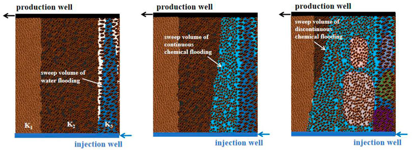
FIGURE 1. Schematic diagram of action mechanism of discontinuous chemical flooding technology (K1<K2<K3).
It can be seen from Figure 1 that various systems such as front slug, main slug, auxiliary slug and secondary slug are organically combined in different stages of discontinuous chemical flooding to achieve the optimal development index. See Table 1 for the design basis of different slugs.
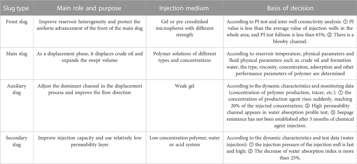
TABLE 1. Design of discontinuous chemical flooding slug.
Technical advantages of this technology
Discontinuous chemical flooding in horizontal wells achieves the purpose of balanced displacement through discontinuous injection mode, which provides ideas and countermeasures for chemical flooding to further improve the utilization rate of chemicals, improve the quality of injection agents, and improve injection efficiency. Compared with conventional single-system chemical flooding, discontinuous chemical flooding in horizontal wells has the following technical advantages.
1) Adjust injection profile and expand sweep volume. Due to the heterogeneity of the reservoir, the diversion rate of the high and low permeability layers is very different, resulting in that the low permeability layer cannot be fully utilized. This phenomenon is particularly obvious in the process of water flooding. Although conventional chemical flooding can alleviate this phenomenon to a certain extent at the initial stage of injection, it will reappear with the advancement of injection, affecting the effect of chemical flooding. Discontinuous chemical flooding can fully adjust the heterogeneity along the horizontal section, expand the swept volume and maximize the reserves between injection and production wells by optimizing the combination of various slugs and discontinuous injection methods, thus ensuring the high speed and high efficiency of the whole process of chemical flooding. Figure 2 shows the diverting rate of each layer of discontinuous system displacement and single system displacement.
2) Increase the contact area with the formation and slow down the increase of injection pressure in the chemical flooding stage. After water flooding is converted to chemical flooding, the injection pressure will increase. Due to the high requirements of offshore safety and environmental protection production, the maximum allowable wellhead pressure is strictly controlled. Compared with directional wells, due to the long horizontal section of horizontal wells and the large contact area with the formation, in the injection stage of chemical flooding, under the condition of completing the same injection volume, the increase of wellhead pressure is relatively small. It can effectively alleviate the problem of injection-production imbalance caused by the fact that the actual injection volume cannot meet the allocated injection volume due to the limitation of wellhead pressure.
3) Remove the pollution near the well and improve the injection capacity. Compared with water flooding, the injection capacity in the chemical flooding stage is decreased, and sometimes the injection pressure is abnormally increased due to near well pollution, well wall scaling and other reasons during the construction process, and the injection volume cannot be reached, which affects the chemical flooding effect. Therefore, the secondary slug with injection increasing effect shall be used to effectively treat the wellbore and near well zone, so as to alleviate the problem of decreasing injection capacity.
4) Improved economy. In the process of discontinuous chemical flooding, the combination of multiple systems at different stages can effectively save operating costs and further improve the economy of chemical flooding.
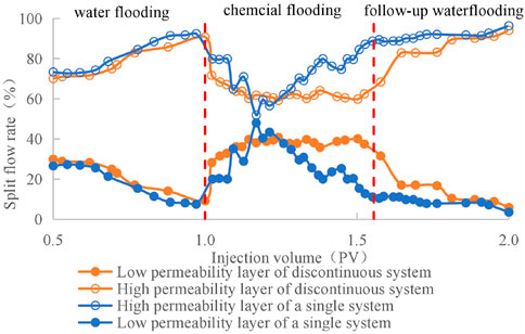
FIGURE 2. Variation curve of split flow rate with injection amount under different injection methods.
Field application example in Bohai B oilfield
Overview of target area
The A sand body of Bohai B oilfield is a shallow water delta front deposit, and the main layer is the Minghuazhen Ⅱ oil group. It is an ultra-high porosity and ultra-high permeability reservoir with an average permeability of 1883mD, a porosity of 30.3%, an effective reservoir thickness of 7m, and a crude oil viscosity of 11.7 mPa·s. In September 2012, it began to develop based on the horizontal well pattern of 3 injection and 4 production. The well location map is shown in Figure 3. The comprehensive water content of the sand body before chemical flooding is 90%. According to the screening principles of chemical flooding in offshore oilfields (Table 2), this sand body is suitable for chemical flooding technology, and the implementation of chemical flooding technology can effectively control the rising trend of water cut and further improve the recovery factor.
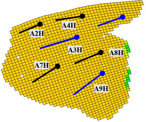
FIGURE 3. Well location map of A sandbody in offshore B oilfield.
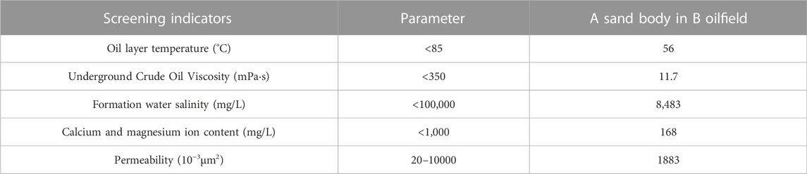
TABLE 2. Screening indicators of chemical flooding reservoirs in offshore oilfields.
The injection wells in this sand body are A3H, A5H, and A9H, and the production wells are A2H, A4H, A7H, and A8H. Based on the analysis of the response relationship between reservoir physical properties and production performance and the understanding of tracer test interpretation results, Well A8H has poor physical properties and poor connectivity with surrounding wells. The injection rate of Well A5H is low, and its main function is to supplement the formation energy. Therefore, the injection wells of the chemical flooding test are selected as A3H and A9H, among which the key effective observation wells for A3H are A2H, A4H and A7H, and the key effective well for A9H is A7H.
Screening and evaluation of injection system
According to the reservoir properties and fluid properties of A sand body, the chemicals used were screened and evaluated. In the selection of the main displacement agent, due to the good quality of the crude oil in the A sand body and the low salinity of the formation water, the main displacement agent is recommended to be a linear polymer based on comprehensive economic considerations. 10 kinds of polymer samples of this type were collected, and the physical and chemical properties and solution properties were tested and evaluated first, and then the reservoir adaptability test was carried out on the reagents with qualified solution properties.
Table 3 shows the test results of 10 samples. It can be seen from the table that the apparent viscosity of PZ1 is not up to the standard, the static adsorption performance of PZ1, PZ9, and PZ10 is unqualified, while the viscosity of PZ1, PZ4, PZ8, PZ9, and PZ10 after thermal stability for 90 days does not meet the evaluation index (more than 12 mPa·s). The reservoir adaptability of the five agents PZ2, PZ3, PZ5, PZ6 and PZ7 all meet the requirements. The fuzzy mathematics method was used to comprehensively score the five qualified chemicals. First, rank the individual properties of polymers according to the experimental results of individual performance evaluation of polymers (Table 3). The score coefficient of the first place is 1.0, the score coefficient of the second place is 0.95, and the score coefficient of the third place is 0.9, and so on. Secondly, the score of single performance of polymer is calculated, which is the score coefficient of ranking multiplied by the weight value of single performance. Finally, the total fraction of the polymer is calculated, that is, the sum of the fractions of each individual property. The final ranking of polymers is based on the total score, and the evaluation result is PZ6>PZ3>PZ2>PZ5>PZ7.
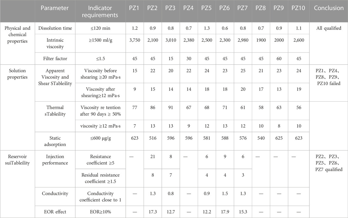
TABLE 3. Performance parameter evaluation results of 10 samples.
On this basis, the concentration of the main oil displacement agent was further optimized. Four groups of experiments with different injection concentrations were set up under the same dosage conditions (Table 4). It can be seen from the experimental results that when the injection concentration is 1,250 mg/L, the magnitude of enhanced oil recovery is the highest. Therefore, the recommended injection concentration of the main flooding agent is 1,250 mg/L.
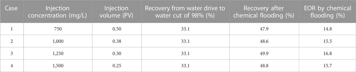
TABLE 4. EOR amplitudes under different injection concentrations.
In the screening of flow direction modifiers, the gel system relies on the evaluated PZ6 polymer as the main agent of the gel system, and evaluates the gelation of the system under different concentrations of polymers, cross-linking agents and additives. Table 5 shows the test results of the gelation time and gelation strength of different gel systems. It can be seen from the table that the gelation time is 2-7 days, and the gelation strength is 1,300–17000 mPa·s. The corresponding strength is formulated according to the production dynamic situation, monitoring data, production concentration and other parameters.
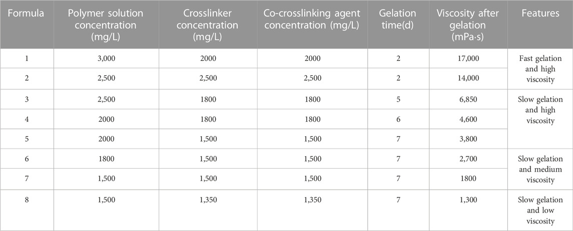
TABLE 5. Gel formulation and post-gelling parameters.
The sand body A is a high-porosity and high-permeability reservoir, and the dispersion system adopts micron-scale pre-crosslinked particles. The index parameters of the dispersion system evaluated by the laboratory experiment are: the solid content is 30%, the initial particle size D50 is 7.5 μm, and the expansion ratio is 3.5 times. The residual drag coefficients at different concentrations were tested (Table 6). It can be seen from the table that the residual resistance coefficient increases with the increase of the concentration, and tends to be stable when it is greater than 0.3%, so the injection concentration is designed to be 0.3%.
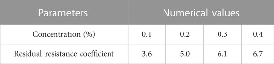
TABLE 6. Residual resistance coefficient corresponding to different concentrations of dispersion system.
The system to increase the injection capacity selects water and acid liquid system and cooperates with the flushing operation. According to the length of the horizontal section, the injection volume of the acid liquid system is designed to be about 250 m (Al Azri et al., 2010).
Design and development scheme
Based on the history matching of the numerical simulation model of A sand body in B oilfield in water drive stage, the reservoir scheme of discontinuous chemical drive was optimized by using CMG numerical simulation software. The model adopts rectangular coordinate system, and the grid of the model is divided into: Nx × Ny × Nz = 64 × 45 × 3.
The principle of production and injection of production wells and injection wells is “determined by production,” and the injection-production ratio is kept at 1.0. The liquid production volume of a single well is determined according to the analysis results of the liquid production capacity in the chemical flooding stage of the production well. The daily production volume of 4 single wells is 150–600 m (Al Azri et al., 2010), and the daily production volume of the whole test area is 1250 m (Al Azri et al., 2010). The daily injection volume of chemical flooding injection wells A3H and A9H is 620 m (Al Azri et al., 2010) and 430 m (Al Azri et al., 2010).
The viscosity-concentration relationship curve of the oil displacement system used in the chemical flooding simulation is mainly based on the laboratory experimental test, and the influence of screen shearing and formation aging on the viscosity loss is also considered. The adsorption curve generally adopts the data of the laboratory experimental test (Figure 4). The other physicochemical parameters required in the numerical simulation are shown in Table 7.

FIGURE 4. The relationship between chemical agent concentration and viscosity and adsorption capacity.
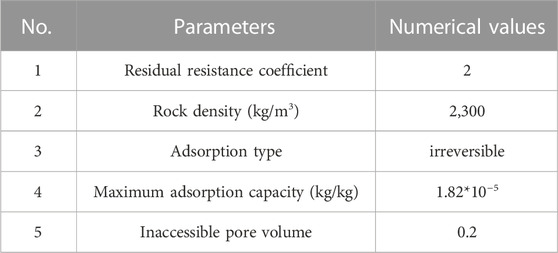
TABLE 7. Values of physical and chemical parameters required for numerical simulation.
Based on the calculation results of injection parameter optimization (Figure 5, Figure 6, Figure 7), it is recommended that the injection rate in the test area is 0.07 PV/a, the cumulative injection slug volume is 0.49 PV, and the injection concentration is 1250 mg/L.Increase oil production per ton of polymer.
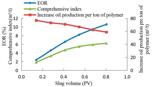
FIGURE 5. Slug volume optimization results

FIGURE 6. Injection concentration optimization results.
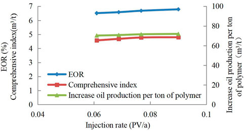
FIGURE 7. Injection rate optimization results.
According to the pressure drop test and calculation results of A3H and A9H (Figure 8), the fullness is 48% and 51%, which is low. It is necessary to adjust the injection profile. Therefore, it is recommended to inject the front slug into the two wells. The injection parameters are shown in Table 8. During the injection process, the auxiliary slug and secondary slug can be injected timely according to the analysis results of monitoring data such as production concentration and tracer test.
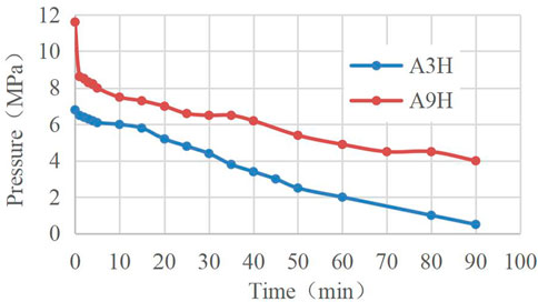
FIGURE 8. Pressure drop test results.
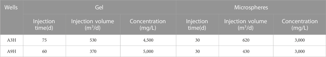
TABLE 8. Injection parameters of pre slug.
Based on the calculation results of the optimization scheme, as of the end of effectiveness, chemical flooding can increase 317,000 m3 of oil compared with water flooding, and improve the oil recovery by 10.4 percentage points compared with basic water flooding, which has good economic efficiency.
Application effect analysis of field test
Wells A3H and A9H started chemical flooding in January and May 2020, respectively. The injection performance curves of the two wells are shown in Figure 9. It can be seen from the figure that during the implementation process, the injection system was adjusted accordingly according to the injection dynamics and the conditions of the corresponding effective wells. The calculation results based on the evaluation indicators such as Hall curve and apparent water absorption index show that the resistance coefficient is established at the injection end, and the injection is effective (Table 9).
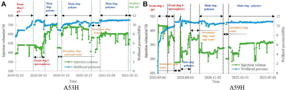
FIGURE 9. Injection performance curve.
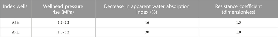
TABLE 9. Injection effectiveness evaluation.
After chemical flooding, the corresponding 4 production wells gradually showed the effect of water cut reduction and oil increase. The single direction effective well A4H at the edge of the reservoir began to take effect on March 4. Compared with water flooding, the daily oil production increased by 89 m (Al Azri et al., 2010)/d at most, with an increase of 151%, and the water cut decreased by 15%. The effective well A7H in both directions began to take effect on May 29. The daily oil production increased by 46 m (Al Azri et al., 2010)/d at the highest, with an increase of 135%, and the water cut decreased by 15%. The production performance curves of the two wells are shown in Figure 10.
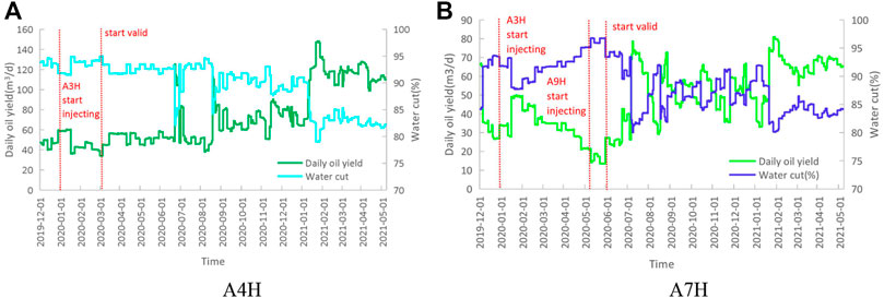
FIGURE 10. Production dynamic curve of production well.
After 2 years and 6 months of chemical flooding in the test area, compared with the basic water flooding, the cumulative oil increase has been 66,000 m3, accounting for 41% of the output of the whole stage. The effect of precipitation oil increase is remarkable. Based on the realized oil price, the calculated input-output ratio is 1:3.7, with good economy. This field test has successfully verified the technical feasibility and economy of the discontinuous chemical flooding technology in horizontal wells. It is recommended to popularize and apply it in horizontal wells in the middle and high water cut period, so as to further improve the injection quality and utilization efficiency of the agent while improving the oil recovery and production rate of the oilfield.
Conclusion
Considering comprehensively the seepage characteristics, heel toe effect and reservoir heterogeneity of horizontal wells, the discontinuous chemical flooding technology for horizontal wells is proposed. According to the production performance, combined with the implementation basis of effective measures, multiple oil displacement systems (polymers of different concentrations, gel of different strengths, microspheres of different sizes and concentrations, acid fluids, and water) are combined and applied at different stages to promote the injection slugs of horizontal wells in a more balanced manner, To reduce the risk of crossflow and profile reversal, so as to achieve the goal of long-term development of horizontal wells.
In the discontinuous chemical flooding technology of horizontal wells, four kinds of slugs are used in combination, namely, front slug, main slug, auxiliary slug and secondary slug, different agents can play a variety of roles in improving mobility ratio, plugging channeling channel, increasing injection, etc. at different positions of the formation, not only adjusting the heterogeneity along the horizontal section but also improving the injection capacity, realizing the balanced displacement of the displacement front edge, and maximizing the reserves between injection and production wells.
The field application of discontinuous chemical flooding technology for horizontal wells has achieved remarkable effect of precipitation and oil increase. After 2 years and 6 months of implementation, the peak growth rate of typical production wells is 151%, and the water cut decreases by 15%. Compared with basic water drive, the cumulative oil increase has been 66,000 m3, and the input-output ratio is 1:3.7. It is expected that 317,000 m3 of cumulative oil increase will be obtained after the entire injection cycle, which will improve the recovery factor by 10.4 percentage points compared with basic water drive, It is suggested to popularize the application in the horizontal wells in the middle and high water cut stage, which is conducive to improving the injection quality and utilization rate of reagents.
Data availability statement
The raw data supporting the conclusion of this article will be made available by the authors, without undue reservation.
Author contributions
ZJ: conceptualization; LD: writing-original draft; WL: data curation; TE: Validation; LX: methodology; ZW: formal analysis.
Conflict of interest
ZJ, LD, WL, TE, LX, ZW were employed by the company China National Offshore Oil Corporation.
Publisher’s note
All claims expressed in this article are solely those of the authors and do not necessarily represent those of their affiliated organizations, or those of the publisher, the editors and the reviewers. Any product that may be evaluated in this article, or claim that may be made by its manufacturer, is not guaranteed or endorsed by the publisher.
References
Al Azri, N., Jamal, E., Murshidi, A., Al Mahrouqi, A., Al Busaidi, L., Kazzaz, A., et al. (2010). “Polymer injection in heavy oil reservoir under strong bottom water drive,” in Presented At The SPE EOR Conference At Oil & Gas West Asia, Muscat, Oman, 11-13 April.
Azrin Al, J., Murshidi, A., Jamal, A., Mahrougi, A., Busaidi, L., Kazzaz, A., et al. (2010). “Polymer injection in heavy oil reservoir under strong bottom water drive,” in Paper Presented At The SPE EOR Conference At Oil & Gas West Asia, Muscat, Oman, 11-13 April 2010.
Bai, B., Zhou, J., and Yin, M. (2015). A comprehensive review of polyacrylamide polymer gels for conformance control[J]. Petroleum Explor. And Dev. 42 (4), 481–487.
Bao, B., Sanders, A., Ren, G., and Haas, T. (2017). Rapid microfluidic analysis of thermal foam stability at 250 degrees celsius[R]. SPE, 188895.
Brooks, A. D., De Zwart, A. H., Bychkov, A., Al-Azri, N., Hern, C. Y., and Mukmin, M. (2010). “Evaluation of EOR techniques for medium-heavy oil reservoirs with A strong bottom aquifer in South Oman,” in Presented At The SPE EOR Conference At Oil & Gas West Asia, Muscat, Oman, 11-13 April.
Cao, R., Han, P., and Hou, W. (2009). Section inversion rules and inversion mechanism of polymer flooding[J]. Acta Pet. Sin. 30 (2), 267–270.
Chang, H., Zhang, L., Jiang, Y., Zhai, S., and Chen, X. (2021). Horizontal well test chart and application under the constraint of shallow water deltaic sedimentation[J]. Oil Gas Explor. And Dev. 39 (1), 74–80.
Delamaide, E., Tabary, R., Zaitoun, A., and Renard, G. (2013). “Pelican Lake field: First successful application of polymer flooding in A heavy oil reservoir SPE-165234-MS,” in SPE Enhanced Oil Recovery Conference, Oklahoma, United States, Apr 25, 2022 - Apr 29, 2022.
Delamaide, E., Zaitoun, A., Renard, G., and Tabary, R. (2013). Pelican Lake field: First successful application of polymer flooding in A heavy oil reservoir. SPE Res Eval Eng 17, 340–354. doi:10.2118/165234-PA
Dwarakanath, V., Dean, R. M., Slaughter, W., Alexis, D., Espinosa, D., Kim, H. N., et al. (2016). “Permeability reduction due to use of liquid polymers and development of remediation options,” in Presented At The SPE Improved Oil Recovery Conference, Tulsa, Oklahoma, USA, 11-13 April. SPE-179657-MS.
Erincik, M. Z., Qi, P., Balhoff, M. T., and Pope, G. A. (2017). “New method to reduce residual oil saturation by polymer flooding", SPE-187230-MS,” in SPE Annual Technical Conference And Exhibition, San Antonio, Texas, USA, 9-11 October.
Gao, C. (2011). Scientific research and field applications of polymer flooding in heavy oil recovery. J. Pet. Explor. Prod. Technol. 1, 65–70. doi:10.1007/S13202-011-0014-6
Heesong, K., Lee, V. B., and Pope, G. A. (2016). “Experimental investigation of the effect of polymers on residual oil saturation, SPE-179683-MS,” in SPE Improved Oil Recovery Conference, Tulsa, Oklahoma, USA, 11-13 April.
Hoteit, H., Alexis, D., Olaoluwa, O., Chawathe, A., et al. (2016). “Numerical and experimental investigation of polymer-induced resistance to flow in reservoirs undergoing A chemical flood,” in Presented At The SPE Annual Technical Conference And Exhibition, Dubai, UAE, 26-28 September. SPE-181720-MS.
Hoteit, H., and Chawathe, A. (2016). Making field-scale chemical enhanced-oil-recovery simulations A practical reality with dynamic gridding. SPE J. 21 (06), 2220–2237. SPE 169688. doi:10.2118/169688-Pa
Howe, A. M. M., Clarke, A., Mitchell, J., Staniland, J., and Hawkes, L. A. (2015). “Visualising surfactant EOR in core plugs and micromodels,” in Paper Presented At The SPE Asia Pacific Enhanced Oil Recovery Conference, Kuala Lumpur, Malaysia, August 2015.
Liang, D., Guozhi, F., Xie, X., and Shi, Y. (2014). Analysis on features and influencing factors of injection production performance during polymer flooding. Special Oil And Gas Reservoirs 21 (5), 75–78.
Liang, D., Kang, X., He, C., Tang, E., and Wang, X. (2018). Water injectivity index prediction model for the well with polymer-flooding in multi-layer heterogeneous reservoir[J]. Special Oil And Gas Reservoirs 25 (5), 109–113.
Lu, X., Cao, B., Xie, K., Cao, W., Liu, Y., Zhang, Y., et al. (2021). EOR mechanisms of polymer flooding in A heterogeneous oil reservoir[J]. Petroleum Explor. And Dev. 48 (1), 148–155.
Pal, S., Mushtaq, M., Banat, F., and Al Sumaiti, A. M. (2018). Review of surfactant-assisted chemical enhanced oil recovery for carbonate reservoirs: Challenges and future perspectives. Pet. Sci. 15 (1), 77–102. doi:10.1007/S12182-017-0198-6
Pinnawala, G., Nizamidin, N., Spilker, K., Linnemeyer, H., Malik, T., and Dwarakanath, V. (2020). “Development of surfactant formulation for harsh environment,” in Presented At The SPE Improved Oil Recovery Conference, Tulsa, OK, USA, 18-22 April. SPE-200394-MS.
Rego, F. B., Botechia, V. E., Correia, M. G., and Schiozer, D. J. (2016). “Quantification of simulation model grid size impact on polymer flooding application in heavy oil heterogeneous reservoir[C],” in SPE Trinidad And Tobago Section Energy Resources Conference, Spain, 13-15 June 2016, 13–15.
Shi, H., He, Y., Sun, Q., Shi, F., and Yue, B. (2020). Research on selective water plugging in offshore fluvial heavy oil reservoir[J]. Nat. Gas And Oil 38 (2), 74–78.
Sorbie, K. S., and Clifford, P. J. (1988). The simulation of polymer flow in heterogeneous porous media[M]. Water-Soluble Polym. Petroleum Recovery 1988, 69–99.
Tan, X., Fan, T., Zhang, L., Liang, X., and Xiao, D. (2021). Impact on remaining oil distribution and well spacing pattern of discontinuous boundary in fluvial reservoir[J]. China Offshore Oil And Gas 33 (2), 123–130.
Xie, X., Kang, X., Zhang, X., Shi, Y., Zeng, Y., and Hou, J. (2016). Chemical flooding potential evaluation method in offshore heavy oilfields and its application[J]. China Offshore Oil And Gas 28 (1), 69–74.
Xu, Y., Shen, M., Zhang, J., Li, X., and Meng, G. (2019). Nanoparticles profile modification technology applied in horizontal well development in offshore reservoir[J]. Energy Chem. Ind. 40 (3), 60–63.
Zhai, S., Sun, G., Chang, H., Chen, X., and Zhang, Y. (2021). New method for evaluating chemical flooding effect of horizontal wells and its oil field application[J]. J. Of Beijing Inst. Of Petrochem. Technol. 29 (2), 30–34.
Keywords: horizontal well, discontinuous, chemical flooding, drug evaluation, scheme design, field application
Citation: Jian Z, Dan L, Liqi W, Engao T, Xianjie L and Wensen Z (2023) Application of horizontal well discontinuous chemical flooding technology in Bohai oilfield. Front. Energy Res. 10:1036835. doi: 10.3389/fenrg.2022.1036835
Received: 05 September 2022; Accepted: 23 November 2022;
Published: 11 January 2023.
Edited by:
Fuyong Wang, China University of Petroleum, Beijing, ChinaReviewed by:
Hussein Hoteit, King Abdullah University of Science and Technology, Saudi ArabiaFalan Srisuriyachai, Chulalongkorn University, Thailand
Copyright © 2023 Jian, Dan, Liqi, Engao, Xianjie and Wensen. This is an open-access article distributed under the terms of the Creative Commons Attribution License (CC BY). The use, distribution or reproduction in other forums is permitted, provided the original author(s) and the copyright owner(s) are credited and that the original publication in this journal is cited, in accordance with accepted academic practice. No use, distribution or reproduction is permitted which does not comply with these terms.
*Correspondence: Liang Dan, liangdan@cnooc.com.cn