Analysis of the Brayton cycle coupled with a small fluoride salt-cooled high-temperature reactor
 Xiuting Liu1
  Yanping Huang
 Minyun Liu
 Luyue Min
- 1Nuclear Power Institute of China (NPIC), Chengdu, China
- 2School of Energy and Power Engineering, Xi’an Jiaotong University, Xi’an, China
Considering the environmental conditions and transportation conditions of remote areas, an inherently safe integrated energy conversion system featuring miniaturization, modularization, and high environmental adaptability is needed. The small fluoride salt-cooled high-temperature reactor (FHR) coupled with the Brayton cycle is a promising design. In this paper, the efficiency, exergy efficiency, and exergy loss of four different configurations of the supercritical carbon dioxide (S-CO2) Brayton cycle coupled with a new small fluoride salt-cooled high-temperature reactor are compared. The S-CO2 recompressor Brayton cycle has the best overall performance. Meanwhile, the effects of the cooling conditions on the thermal efficiency and exergy efficiency of different cycle configurations are discussed. When the core outlet temperature is 700°C, the efficiency of the designed S-CO2 recompressor Brayton cycle is approximately 42–44% when the cycle minimum temperature is 20–40°C. In conclusion, the designed small FHR coupled with the Brayton cycle system offers interesting performances in power generation, mineral mining, industrial steam supply, molten salt energy storage, and high-temperature hydrogen production in remote areas.
1 Introduction
Regarding the fourth-generation nuclear power systems, six candidate reactor types, including the ultrahigh temperature reactor, supercritical water reactor (Pegallapati et al., 2020; Deev et al., 2021), gas-cooled fast reactor (Matozinhos et al., 2022; Lima-Reinaldo and François, 2023), lead-cooled fast reactor (Massone et al., 2022; Lima-Reinaldo and François, 2023), sodium-cooled fast reactor (Tak et al., 2022), and molten salt reactor (Ingersoll et al., 2004; Delpech, 2013), have been proposed. Studies of new reactors and coupled power systems have been a research focus worldwide. Among them, the molten salt reactor (MSR) is a kind of nuclear fission reactor, and its primary coolant is a kind of molten mixed salt. The MSR can maintain a lower pressure when working at high temperatures (higher thermal efficiency can be obtained), thus reducing the mechanical stress and improving the safety.
From 2001 to 2003, the Oak Ridge National Laboratory (ORNL) (Ingersoll and Forsberg, 2006; Forsberg et al., 2013), Sandia National Laboratories (SNL), and the University of California, Berkeley (UCB), jointly developed the concept of a fluoride salt-cooled high-temperature reactor (FHR) (Haubenreich et al., 1964; Scott and Grindell, 1967). In 2007, the UCB carried out simulations of the PB-AHTR (Bardet et al., 2008) by RELAP5-3D and believed that it had a higher power density than the high-temperature helium-cooled reactor.
The ORNL proposed a new FHR concept called the SmAHTR (Greene et al., 2010), which is based on the research on the AHTR in 2006. The SmAHTR adopted the modular design concept with a 125-MW thermal power and a 60-year design life. The core inlet and outlet temperatures are 670°C and 700°C, respectively (Ilas et al., 2014).
Meanwhile, the Shanghai Institute of Applied Physics of the Chinese Academy of Sciences has built platforms for molten salt chemistry experiments and started the construction of a 2-MWt liquid fuel thorium-based molten salt reactor (Ruan Jian, 2017). Xi’an Jiaotong University (Qin Hao, 2018) also built an experimental platform for molten salt flow heat transfer and passive residual heat removal systems and carried out a series of studies in core physical and thermal design, safety analysis, etc.
In conclusion, the development of the FHR is still in the stage of a concept proposal, basic theory, and experimental research. Research on the coupled power conversion system of molten salt reactors is still limited. Compared with the light water reactor, the outlet temperature of the FHR is much higher and is potentially compatible with several highly efficient power conversion technologies. A particularly appealing option for the system is the high-efficiency S-CO2 Brayton cycle. In recent years, with the breakthrough of key technologies such as heat exchangers and turbines, the supercritical carbon dioxide cycle has received extensive attention. However, there are few studies on the cycles coupled with the FHR, which is important for designing an integrated energy conversion system.
In this paper, an innovative and modular advanced nuclear power system, which consists of a small modular FHR and an S-CO2 Brayton cycle, is proposed. Based on the thermal−hydraulic design of the proposed FHR, different configurations of the S-CO2 Brayton cycle are discussed from the perspective of energy analysis and exergy analysis. Considering the probable climate in remote regions, the effects of the cooling conditions are further analyzed.
2 Small modular advanced nuclear power systems
2.1 System layouts
Considering the compact and integrated design requirements of the small modular FHR, helical cruciform fuel made of TRISO was selected. The fuel cladding is made of a special carbon−carbon (C−C) material (Greene et al., 2010), and the moderator is made of graphite (Jiang et al., 2022). A three-dimensional continuous energy Monte Carlo particle transport program was adopted in neutronic analyses. The computational fluid dynamics software Fluent and STAR-CCM+ based on the Euler method were used in the thermal−hydraulic calculations.
The FLiBe (Sehgal, 2012) coolant is heated when flowing through the core, and then, it flows upward along the ascending segment. After leaving the ascending segment, the coolant is deflected at the top and flows downward into the intermediate heat exchanger to release heat. The coolant enters the main pump for pressurization. In the pump outlet, most of the coolant returns to the core along the downcomer, and the other small part returns to the direct heat exchanger (DHE) for waste heat discharge. After meeting with the main coolant from the core, it enters the FLiBe−FLiNaK intermediate heat exchanger again, forming a primary loop. The diagram of the primary loop is shown in Figure 1. The FLiNaK−CO2 intermediate heat exchangers were set between the reactor core coolant and the supercritical carbon dioxide (S-CO2) power cycle system. The FLiNaK−CO2 intermediate heat exchangers transfer the reactor heat to the power conversion cycle and finally realize the conversion of heat energy to electric energy.
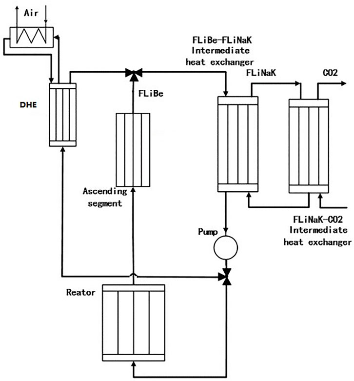
FIGURE 1. Diagram of the primary loop of the FHR.
The advantages and disadvantages of different pellet materials are compared, as shown in Table 1. The comparative analysis results show that UZr fuel and TRISO fuel both have a high thermal conductivity and a small temperature gradient; thus, the temperature of the fuel and cladding can meet the requirements of the temperature limits under normal operation and during accidents (Haynes-International, 2002; Clarno et al., 2007), and both fuels can contain fission gas, thus reducing the possibility of a large-scale release of radioactive materials. It can be used as a candidate material for high-safety fuel schemes. HT9 stainless steel and C−C composites were selected as candidate cladding materials for the high-safety fuel scheme. Between them, HT9 is used as a UZr fuel cladding, and the C−C composite is used as a TRISO-type fuel cladding. After comparing and analyzing the slowing properties of light water, heavy water, graphite, and beryllium and considering the chemical stability, thermal conductivity, and mechanical properties, the two candidate schemes of no slowing and graphite were finally selected. Between them, no slowing was used as the moderator scheme of the UZr fuel, and graphite was used as the moderator scheme of the TRISO fuel. Combined with the chemical stability, flow heat transfer characteristics, and neutron effect, FLiBe with a low viscosity, good thermal conductivity, and better neutron performance was selected as the coolant. The molar ratio of LiF to BeF2 was 2:1, and the Li-7 enrichment was 99.99%. Molten FLiNaK salt is used as the heat transfer medium in the primary loop and the passive residual heat removal system, which has the characteristics of low cost, moderate viscosity, and benefits from natural circulation. The helical cruciform fuel, which is superior to traditional PWR fuel in terms of convective heat transfer, cladding damage, radiation swelling, and other indicators, is finally adopted to determine the helical cruciform fuel, dispersion core material, C−C composite cladding, graphite slowing, and multicomponent compact core designs. Figure 2 shows the single-channel geometric model of the helical cruciform fuel.
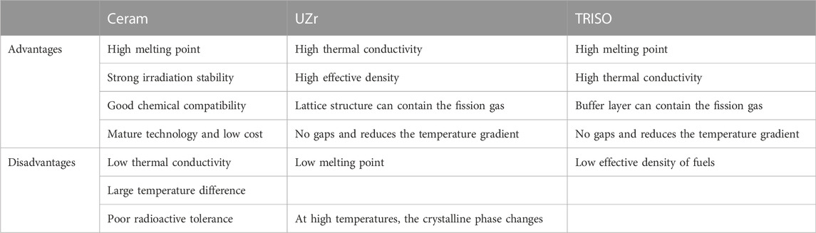
TABLE 1. Advantages and disadvantages of different pellet materials.
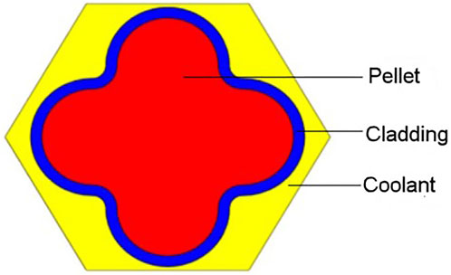
FIGURE 2. Single-channel geometric model.
The non-thermal equilibrium porous medium model of STAR-CCM+ simulating the physical velocity is used to carry out the thermal−hydraulic calculation of the one-sixth core of the FHR reactor. The equation of single-phase incompressible non-thermal equilibrium porous media simulating physical velocity in STAR-CCM+ is as follows:
Figure 3B shows the physical calculation model of a one-sixth core. This calculation model has the same structure size as the calculation model of the whole core; the only difference is that the one-sixth of the whole core is selected, and a reflective boundary is set. The material layout and component number are shown in Figure 3. Figure 4 shows the longitudinal section and cross section of the one-sixth core model of the FHR established by using the MCNP modeling method. Based on the actual fission power distribution of each component calculated by the MCNP, the mass flow distribution of the coolant in each component is calculated as the inlet boundary condition for the CFD calculation. Thermal−hydraulic analyses and calculations are carried out using STAR-CCM+. The geometric model and CFD calculation model are shown in Figure 5. During the CFD calculation, the coolant, fuel, and cladding inside each hexagon assembly are set as the porous media area, the component graphite box and radial graphite reflector are set as the solid, and the turbulence model is the k-SST model. The design parameters of the S-CO2 power cycle system are shown in Table 2.
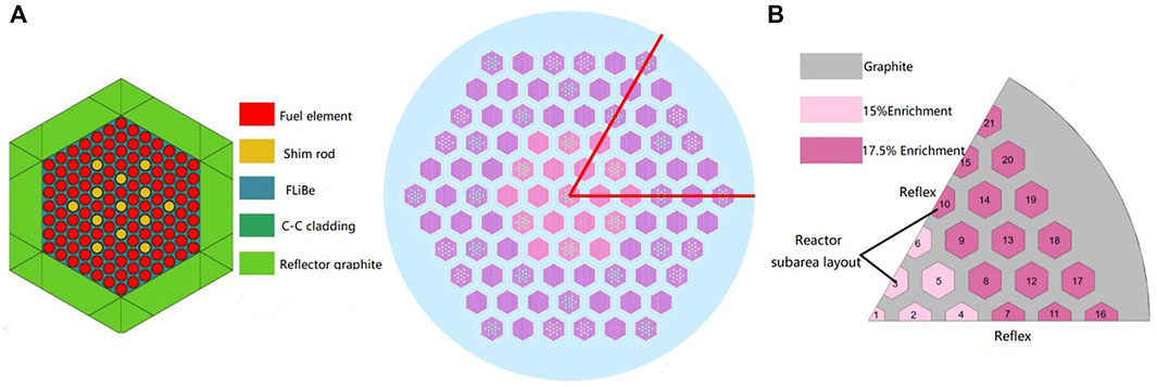
FIGURE 3. FHR core model. (A) Full-core model and (B) 1/6 core model.
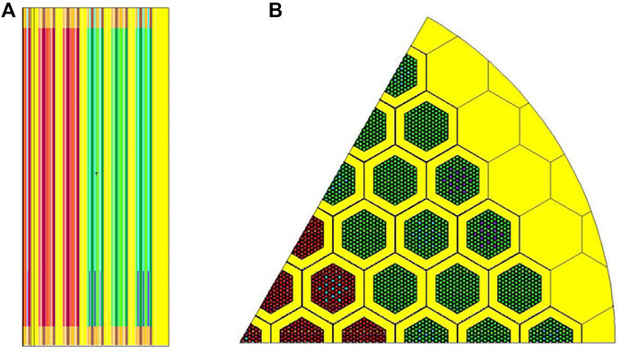
FIGURE 4. Core model in the MCNP. (A) Longitudinal section and (B) cross section.
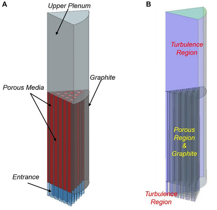
FIGURE 5. Core thermal−hydraulic model. (A) the geometric model (B) the CFD calculation model.
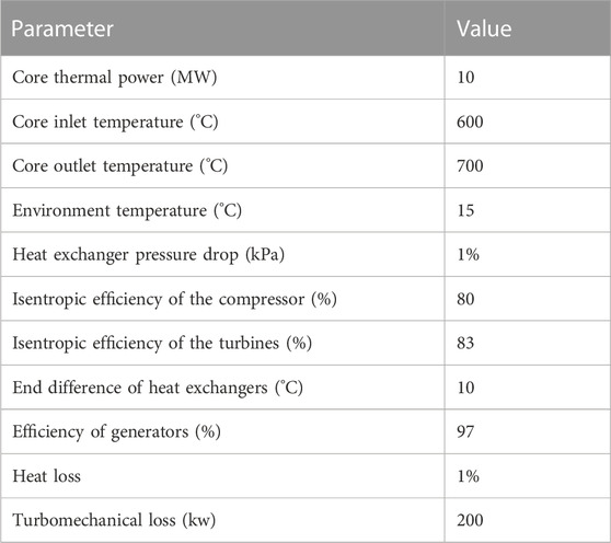
TABLE 2. Cycle parameter settings.
2.2 Thermodynamic analyses
Considering the differences in the cycle configurations, the thermodynamic analysis conclusions, equipment operating parameters, optimal configurations, cycle performance evaluation criteria, and optimization results are different. The following is a comparative analysis of the Brayton cycle configurations to provide theoretical and data references for the preliminary design of small fluoride reactor systems. A small fluoride-cooled high-temperature reactor can be matched with a variety of Brayton cycle configurations. Taking the recompression Brayton cycle as an example, the cycle flow chart is shown in Figure 6.

FIGURE 6. Flow chart of the recompression Brayton cycle.
After heat absorption occurs in the 1−2 processes, the working medium enters the turbine to complete the 3−4 work processes. The exhaust gas after work is discharged through the low-pressure side of the 5−6 high-temperature recuperator and the low-pressure side of the 6−7 low-temperature recuperator. It is divided from the outlet of the low-temperature recuperator. One enters the cooler and the main compressor after the 8−9 heat release process. After the 10−12 pressurization of the main compressor, it enters inlet 14 at the cold side of the low-temperature recuperator; the other enters the recompressor for the 11–13 repressure process directly. The working fluid from the recompressor joins the working fluid passing through the high-pressure side of the low-temperature regenerator, enters the high-pressure side of the high-temperature regenerator to complete the 15–1 heat absorption process, and finally enters the 1−2 intermediate heat exchanger to absorb heat, completing the whole cycle.
To carry out the thermodynamic analysis and analytical modeling of the system (Liu et al., 2020; Yourong, 2020), the initial assumptions are as follows:
1) The system components operate stably under various working conditions without considering the potential energy and the kinetic energy.
2) Ignoring the pressure drop of the pipeline, the pressure drop of the system is only the pressure drop of the heat exchanger.
3) The working process of the turbomachinery is adiabatic but not isentropic. Based on the first law of thermodynamics and the second law of thermodynamics, the energy balance relationship is established. The basic formula of the thermodynamics law can be expressed as follows:
The heat input of the fluorine salt-cooled high-temperature reactor core can be expressed as follows:
The isentropic work of the compressor and turbine can be determined by the following relationships:
The network of the cycle system can be expressed as follows:
The thermoelectric conversion efficiency of the system can be expressed as follows:
Exergy analysis is an effective tool to describe energy quality and reduce irreversibility. It can measure the energy conversion and work carried out by a system or equipment from the perspective of energy availability. Based on thermodynamic exergy analysis, a balance equation of the available energy can be established. The basic equation of physical exergy at a certain point can be expressed as follows:
The efficiency is expressed as follows:
The total loss of each component can be expressed as the total loss of all key components, and the loss of each component can be calculated by Table 1.
3 Small modular advanced nuclear power system
The most typical S-CO2 Brayton cycle is the simple regenerative cycle. In the simple regenerative cycle, the working medium directly enters the turbine for work after heating in the intermediate heat exchanger. The exhaust gas after work flows through the regenerator and the cooler for cooling and finally enters the compressor. After being pressurized by the compressor, the working medium returns to the regenerator, is heated by the working medium on the low-pressure side, and finally enters the intermediate heat exchanger to form a whole cycle.
In the recompression cycle, an additional compressor and an additional regenerator are introduced based on a simple regenerative cycle to split the flow. Based on the recompression cycle, inter-stage cooling is introduced to form an intermediate cooling structure, which is called the recompression intermediate cooling cycle. The reheating structure increases the multi-stage reheating between the turbine stages to increase the turbine output power, which is called the reheating cycle. Figure 6, Figure 7, Figure 8, and Figure 9 show the flow chart of the recompression cycle, simple regenerative cycle, intermediate cooling recompression cycle, and reheat recompression intermediate cooling cycle.
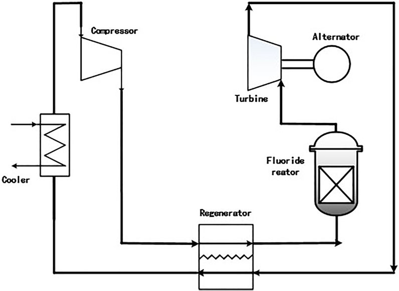
FIGURE 7. Flow chart of the simple regenerative cycle.
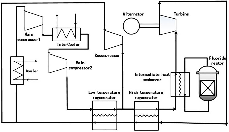
FIGURE 8. Flow chart of the intercooling recompression cycle.
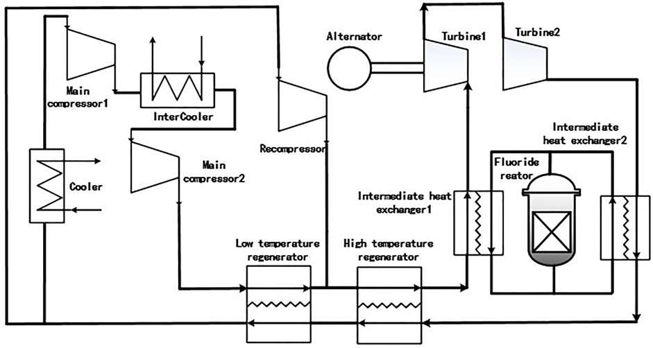
FIGURE 9. Flow chart of the reheat recompression intermediate cooling cycle.
3.1 Analysis of different cycle configurations
To discuss the compatibility with a small fluoride-cooled high-temperature reactor, four typical supercritical carbon dioxide Brayton cycles, including the single-stage regenerative cycle, recompression cycle, main pressure intercooling cycle, and reheat recompression cycle, are selected for comparative analyses. The initial parameters of the selected cycle are listed in Table 2.
The application background of small fluoride-cooled high-temperature reactors is remote areas in western China. Considering the adaptability of the environment, the circulating cooling mode is air-cooling circulation, and the ambient temperature is 25°C.
According to the aforementioned assumptions, the system input parameters, energy balance, and exergy balance are used to calculate the thermoelectric conversion efficiency, exergy efficiency, and exergy loss distribution of the four configurations.
Figure 10 shows that with the introduction of the split flow recompression, and intercooling and reheating structures, the thermoelectric conversion efficiency of the supercritical carbon dioxide Brayton cycle gradually increases. Compared with the simple regenerative cycle, the thermal efficiency of the recompression cycle increases by approximately 5%, while that of the intercooling recompression cycle and the reheating intercooling recompression cycle increases by approximately 0.5%, which is far less than the increase in the efficiency of the recompression cycle compared with the simple regenerative cycle. The cycle efficiency increases gradually with the introduction of the recompression split flow and intercooling structure, while the cycle efficiency decreases slightly with the introduction of the reheat structure. In summary, with the introduction of intercooling and reheating structures, the cycle thermoelectric conversion efficiency has been improved. However, the extent of improvement is limited, and the volume of the system complexity level has gradually increased. In the recompression Brayton cycle, due to the introduction of the additional compressor and the low-temperature regenerator, the energy utilization rate is improved, and the existence of the split flow effectively reduces the heat exchange pinch point problem of the low-temperature regenerator. The introduction of an intercooling structure can play an effective cooling role between the compressor stages and greatly reduce the power consumption of the compressor. The introduction of a reheat structure between turbine stages can increase the output work of the turbine, increase the average heat absorption temperature, and thus improve the thermal efficiency.
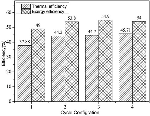
FIGURE 10. Comparison of the thermal efficiency and exergy efficiency of different cycle configurations.
Figure 11A–D shows the loss distribution of four typical supercritical carbon dioxide reprocessing Brayton cycles. It can be seen from the loss distribution that the turbine loss is large in all four configurations. It can be seen from a) that in the simple regenerative Brayton cycle, the loss of the regenerator link is the largest and even exceeds the loss of the turbine. This is because the regenerator may have pinch points, the regeneration is insufficient, and the available energy is reduced. From B−C, the loss of the compressor is greatly reduced when the reheater is introduced into the recompression structure, and the loss of the compressor is reduced after the introduction of the intercooling structure. This also explains the perspective of exergy analysis that the split flow recompression structure can effectively reduce the pinch point of the regenerator and that the introduction of an intercooling structure can reduce the power consumption of the compressor to improve the cycle thermal efficiency and exergy efficiency. It can be seen from D that the total loss of the turbine is still the largest. However, compared with the recompression cycle and the main pressure intercooling recompression cycle, the loss of the intermediate heat exchanger has increased, which also explains why the efficiency of the reheating intercooling recompression cycle is slightly lower than that of the intercooling recompression cycle.
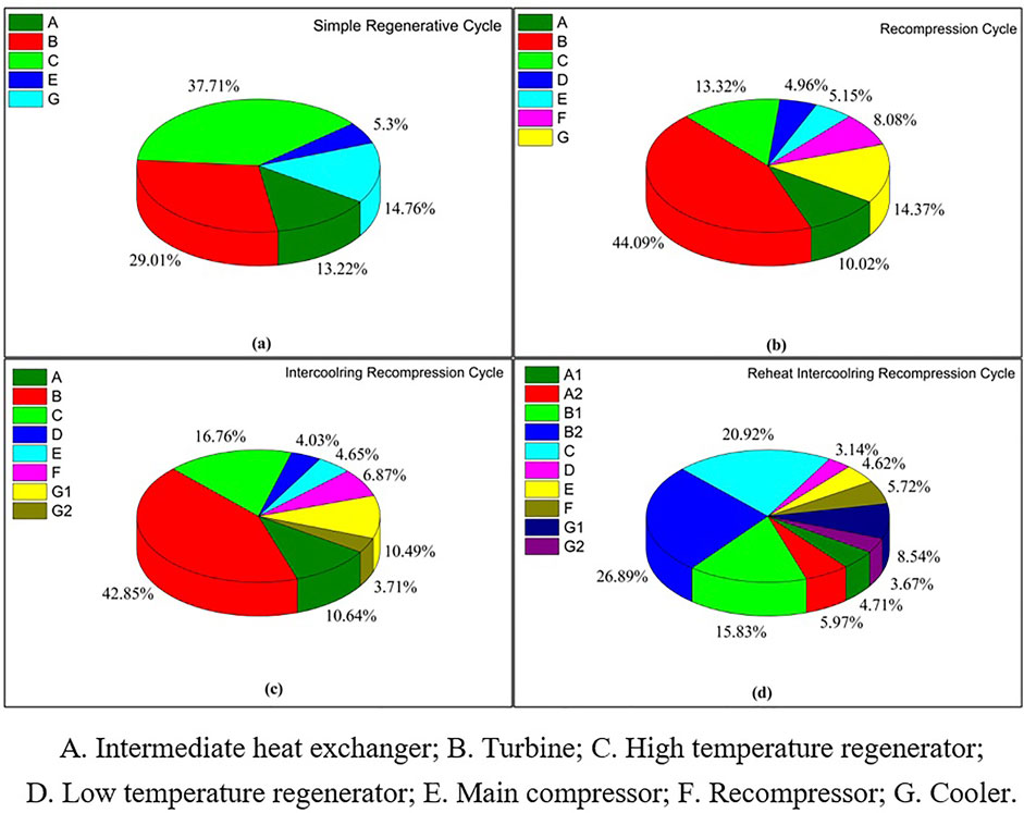
FIGURE 11. Exergy loss distribution of different cycle configurations. (A) Simple Regenerative Cycle (B) Recompression Cycle (C) Intercooling Cycle (D) Reheat Intercooling Recompression Cycle.
3.2 Effects of different cooling conditions
Considering the environmental characteristics of the western region, the air-cooling mode of anhydrous cooling is adopted for the S-CO2 Brayton cycle cooling of a small fluoride-cooled high-temperature reactor. Taking the typical climate data on western China as the input, the influence of the cycle minimum temperature on the thermal efficiency and exergy efficiency of different cycle configurations was discussed. The typical climate data are shown in Table 3. Considering the annual maximum air temperature in the typical areas, the calculation results of different cycle configurations between 32°C and 40°C are analyzed. Figure 12A–Dshows that the ambient temperature is very important to the temperature of the compressor inlet working medium. The higher the regional temperature is, the worse the cooling conditions are (Table 4). The higher the temperature of the compressor inlet working medium is, the worse the effect of the compressor inter-stage cooling is. The greater the power consumption of the compressor, the lower the circulating thermal efficiency and efficiency are. It can be seen from the analysis results that, considering the temperature environment in the western region, the optimal configuration for matching the small fluoride-cooled high-temperature reactor is the cycle without the intercooling structure, and the recommended recompression cycle configuration with high efficiency and compactness is the optimal configuration for matching the supercritical carbon dioxide cycle.
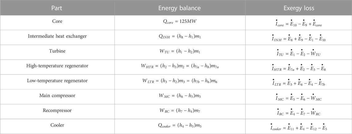
TABLE 3. Energy balance and exergy balance relationship.

FIGURE 12. Efficiency of different configurations at different cycle minimum temperatures.
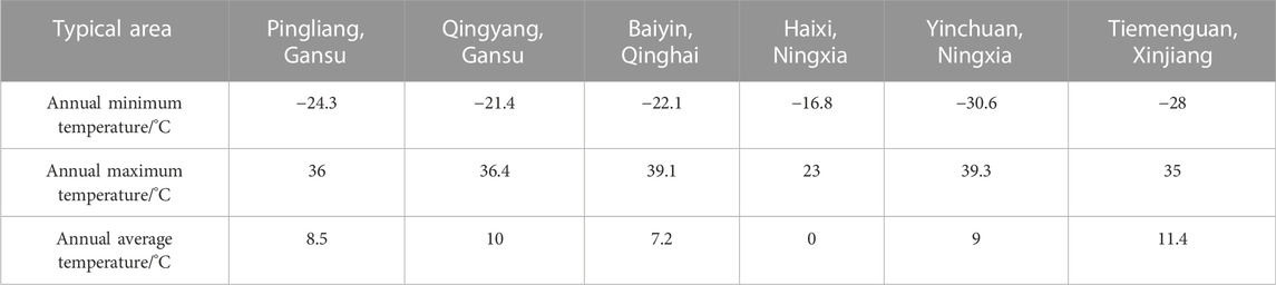
TABLE 4. Typical climate data.
4 Conclusion
Based on the energy demand and utilization in western China, the S-CO2 Brayton thermoelectric conversion system that matches the small fluoride-cooled high-temperature reactor is modeled in this paper. Moreover, the cycle efficiency of four typical configurations, such as a simple regenerative cycle, is compared using the methods of energy analysis and exergy analysis, and the thermoelectric conversion system matching the small fluoride-cooled high-temperature reactor is obtained. The following conclusions are then developed.
The introduction of the split flow recompression structure reduces the loss of the regenerator, thereby improving the circulation efficiency. The introduction of the intercooling structure reduces the power consumption of the compressor, thus improving the cycle thermal efficiency. However, the efficiency is greatly affected by the ambient temperature, especially in air-cooling conditions.
The S-CO2 recompression Brayton cycle has a high compactness and high thermoelectric conversion efficiency. Compared with the indirect cooling cycle, the efficiency of the recompression cycle is less affected by the environmental temperature. Meanwhile, the recompression cycle is much simpler than the reheat cycle, which reduces the cost and control difficulty. Considering the climate factors and transportation conditions in the western region, the supercritical carbon dioxide recompression cycle has the highest adaptability to the small fluoride-cooled high-temperature reactor and is conducive to the realization of future mobile power supplies.
Data availability statement
The raw data supporting the conclusions of this article will be made available by the authors, without undue reservation.
Author contributions
XL: software, methodology, and writing—original draft; ML: methodology and analysis; LM: analysis; XL: analysis; WZ: methodology and supervision; and YH: conceptualization, funding acquisition, and supervision. All authors contributed to the article and approved the submitted version.
Funding
This work was supported by the National Key Research and Development program of China (2020YFB1902000).
Conflict of interest
The authors declare that the research was conducted in the absence of any commercial or financial relationships that could be construed as a potential conflict of interest.
Publisher’s note
All claims expressed in this article are solely those of the authors and do not necessarily represent those of their affiliated organizations, or those of the publisher, the editors, and the reviewers. Any product that may be evaluated in this article, or claim that may be made by its manufacturer, is not guaranteed or endorsed by the publisher.
References
Bardet, P., Blandford, E., Fratoni, M., Niquille, A., Greenspan, E., and Peterson, P. F. (2008). Design, analysis and development of the modular PB-AHTR. Proceedings of the International Conference of Asian Political Parties. Anaheim, CA USA.
Clarno, K., Forsberg, C., Gehin, J., Slater, C., Carbajo, J., Williams, D., et al. (2007). Trade studies for the liquid-salt-cooled very high-temperature reactor: Fiscal year 2006 progress report. ORNL/TM- 140, 35 .
Deev, V., Kharitonov, V., Baisov, A., and Churkin, A. (2021). Hydraulic resistance of supercritical pressure water flowing in channels–A survey of literature. Nucl. Eng. Des. 380, 111313. doi:10.1016/j.nucengdes.2021.111313
Delpech, S. (2013). Molten salts for nuclear applications molten salts chemistry. Elsevier, 497–520. Amsterdam, Netherlands.
Forsberg, C., Hu, L.-W., Peterson, P. F., and Sridharan, K. (2013). Fluoride-salt-cooled high-temperature reactors (FHRs) for base-load and peak electricity, grid stabilization, and process heat. Cambridge, MIT-ANP-: Massachusetts Institute of Technology: Center for Advanced Energy Systems. TR-147.
Greene, S. R., Gehin, J. C., Holcomb, D. E., Carbajo, J. J., Ilas, D., Cisneros, A. T., et al. (2010). Pre-conceptual design of a fluoride-salt-cooled small modular advanced high-temperature reactor (SmAHTR). Oak Ridge National Laboratory. ORNL/TM-2010/199.
Haubenreich, P., Engel, J., Prince, B., and Claiborne, H. (1964). MSRE design and operations report. Part III. Nuclear analysis. Retrieved from.
Ingersoll, D., Forsberg, C., Ott, L., Williams, D., Renier, J., Wilson, D., et al. (2004). Status of preconceptual Design of the advanced high-temperature reactor (AHTR): United States. Department of Energy.
Ingersoll, D., and Forsberg, C. (2006). Overview and status of the advanced high-temperature reactor,” in Proceedings of the international congress on advanced nuclear power plants. Reno, Nevada. Paper presented at theJune 4–8.
Jiang, D., Zhang, D., Li, X., Wang, S., Wang, C., Qin, H., et al. (2022). Fluoride-salt-cooled high-temperature reactors: Review of historical milestones, research status, challenges, and outlook. Renew. Sustain. Energy Rev. 161, 112345. doi:10.1016/j.rser.2022.112345
Lima-Reinaldo, Y., and François, J.-L. (2023). Fuel loading pattern optimization of ALLEGRO fast reactor using genetic algorithms. Ann. Nucl. Energy 180, 109451. doi:10.1016/j.anucene.2022.109451
Liu, X., Zhang, H., Yin, D., Chai, X., and Xiu, Z. (2020). Based on SCO2 Performance analysis of dual-mode nuclear thermal propulsion system of Brayton cycle Nuclear Power Engineering. doi:10.13832/j.jnpe.2020.S2.0102
Massone, M., Abrate, N., Nallo, G. F., Valerio, D., Dulla, S., and Ravetto, P. (2022). Code-to-code SIMMER/FRENETIC comparison for the neutronic simulation of lead-cooled fast reactors. Ann. Nucl. Energy 174, 109124. doi:10.1016/j.anucene.2022.109124
Matozinhos, C. F., Carroll, A. D., Menezes, C., Vaghetto, R., and Hassan, Y. (2022). Experimental measurements of fluid flow in an 84-pin hexagonal rod bundle with spacer grid for a gas-cooled fast modular reactor. Int. J. Heat Fluid Flow 97, 109014. doi:10.1016/j.ijheatfluidflow.2022.109014
Pegallapati, A. S., Banoth, P., and Maddali, R. (2020). Dynamic model of supercritical CO2 based natural circulation loops with fixed charge. Appl. Therm. Eng. 169, 114906. doi:10.1016/j.applthermaleng.2020.114906
Qin Hao, W. C., and Zhang, D. (2018). Numerical study on tritium transport characteristics of fluoride cooled high-temperature reactor. Sci. Technol. Atomic Energy 52 (3), 6.
Ruan Jian, Z. Y., Li, M., Zhou, B., Zhu, G., and Xu, H. (2017). Study on the transient behavior of the air Brayton cycle system for fluoride salt cooled high-temperature reactor. Nucl. Power Eng. 38 (4), 22–26.
Scott, D., and Grindell, A. (1967). Components and systems development for molten-salt breeder reactors. Retrieved from.
Sehgal, B. R. (2012). Chapter 1 - light water reactor safety: A historical review,” in Nuclear safety in light water reactors. Editor B. R. Sehgal (Boston: Academic Press), 1–88.
Tak, N.-i., Sik Lim, H., Hong, J., Yoon, J., Ha Park, B., and Eoh, J. (2022). Improvement of GAMMA+ code for system transient and thermo-fluid safety analysis of sodium-cooled fast reactors. Nucl. Eng. Des. 399, 112002. doi:10.1016/j.nucengdes.2022.112002
Glossary
Nomenclature
m mass flow
p pressure
T temperature
h enthalpy
s entropy
W work
Q thermal power
ηth thermoelectric conversion efficiency
ηth exergy efficiency
U velocity
Us apparent velocity
χ porosity
Pv viscosity tensor
Pi inertia tensor
q heat flux;
HTR heat transfer convection coefficient
a interface density
Subscripts
in inlet
out outlet;
net net work
core reactor core
env environment
T turbine
C compressor
MC main compressor
RC recompressor
Keywords: fluoride salt-cooled reactor, Brayton cycle, supercritical carbon dioxide, exergy, efficiency
Citation: Liu X, Huang Y, Liu M, Min L, Zhang T, Li X and Zhuo W (2023) Analysis of the Brayton cycle coupled with a small fluoride salt-cooled high-temperature reactor. Front. Energy Res. 10:1097023. doi: 10.3389/fenrg.2022.1097023
Received: 13 November 2022; Accepted: 25 November 2022;
Published: 26 January 2023.
Edited by:
Shanfang Huang, Tsinghua University, ChinaReviewed by:
Yuan Zhou, Sichuan University, ChinaHaochun Zhang, Harbin Institute of Technology, China
Copyright © 2023 Liu, Huang, Liu, Min, Zhang, Li and Zhuo. This is an open-access article distributed under the terms of the Creative Commons Attribution License (CC BY). The use, distribution or reproduction in other forums is permitted, provided the original author(s) and the copyright owner(s) are credited and that the original publication in this journal is cited, in accordance with accepted academic practice. No use, distribution or reproduction is permitted which does not comply with these terms.
*Correspondence: Yanping Huang, hyanping007@163.com