Study on the effect of waveform film holes on film cooling efficiency
 Cheng Qian
 Mingwei Wang2
 - 1College of Energy and Power Engineering, Nanjing University of Aeronautics and Astronautics, Nanjing, China
- 2College of Information Science and Engineering, East China University of Science and Technology, Shanghai, China
In order to improve the film cooling efficiency of the cooling gas on the hot side wall of the plate, the flow field, temperature field and the average film cooling efficiency of the cylindrical hole, rectangular hole and waveform hole near the wall were compared and analyzed by numerical calculation method. Compared with cylindrical holes, the average spanwise film cooling efficiency of rectangular hole is improved by 100%, and the average spanwise film cooling efficiency of waveform hole is improved by 130%. In addition, the effects of the amplitude A of the waveform hole and the initial phase ϕ on the cooling efficiency are compared and analyzed. The results show that: Within the scope of this study, when the blowing ratio M = 1, lifting the initial phase ϕ of the waveform hole can effectively improve the film cooling efficiency of the cooling gas on the wall. When the amplitude A of the waveform hole is raised, the film cooling efficiency of the cooling gas on the wall will first increase and then decrease, reaching the maximum at the amplitude A = 0.4D. At low blowing ratio, the geometric structure of waveform hole has little influence on the cooling effect of wall surface. Under high blowing ratio, when the geometric structure of waveform hole is changed, the influence of secondary flow on the average spanwise cooling efficiency of wall surface is great.
1 Introduction
With the improvement of the performance requirements of aeroengine, the inlet temperature of hot end components also gradually increases. At present, the gas temperature of advanced aeroengine has far exceeded the temperature resistance limit of materials. In order to ensure the service life of the structure, appropriate cooling methods must be adopted. Air film cooling is a kind of cooling method with high efficiency and wide application range. It is the main external cooling method at present and has been widely used in engine cooling design so far in the researches of Han et al. (2012), Bunker (2017), Baldauf et al. (2002), Miller and Crawford (1984). Many scholars at home and abroad have studied the effect of air film orifice pattern on cooling efficiency. Compared with the traditional cylindrical holes, the special-shaped holes can effectively reduce the adverse effects of renal vortex in the researches of Okita and Nishiura (2007), Walters and Leylek (2000). Gritsch demonstrated through experiments that the film cooling effect of the simplestspecial-shaped hole is obviously better than that of the cylindrical hole in the research of Gritsch et al. (2000). Baheri compared and analyzed the cooling effects of circular gas film holes, expanded gas film holes, circular gas film holes with shallow grooves and expanded gas film holes with shallow grooves. The results showed that the shape of holes can significantly affect the formation of gas film in the research of Baheri et al. (2008). Yang’s research shows that at low blow air ratio, the film cooling efficiency ratio of the special-shaped hole has little change compared with that of the cylindrical hole, but at high blow air ratio, the reverse pair vortex generated by the special-shaped hole helps to improve the film cooling efficiency in the research of Yang et al. (2015). Colban discussed the influence of geometric parameters of sector air film holes on cooling efficiency and gave an empirical formula for predicting the average spanwise cooling efficiency of sector air film holes downstream in the research of Colban et al. (2008). Karsten proposed the nekomimi-shaped film hole, and carried out preliminary experimental and numerical simulation studies. The results show that the nekomimi-shaped film hole inhibits the formation of CRVP, and the wall effect of the jet is improved, thus improving the film cooling efficiency in the research of Kusterer et al. (2012). SCHMIDT D L compared the round hole with the compound angle hole, and the results showed that the compound angle hole has better cooling performance in the research of Schmidt et al. (1996). Shengchang Zhang concluded that the structure can significantly improve the uniformity and effect of air film cooling through the numerical simulation of a cat’s ear shaped air film hole in the research of Zhang et al. (2021). In addition, R.S. Boker, Yu.G. Gorelova, KUSTERER K and others have also proposed the optimal design of a variety of gas film pore structures and carried out relevant analysis and discussion in the researches of Bunker (2011), Gorelov and Tyul’kov (2018), Kusterer et al. (2013). Although a large number of studies have been carried out at home and abroad on the influence of different shapes of air film holes on the cooling efficiency of air film, few scholars have explored the influence of geometric structure of corrugated holes on the cooling efficiency of air film on hot side wall, and the flow heat transfer mechanism of waveform holes is still unclear. Therefore, the commercial software Fluent 2020 was used in this paper for numerical calculation to analyze the influence of the amplitude and phase angle of waveform holes on the cooling efficiency of the air film on the flat wall, and to compare the cooling effect with that of rectangular holes and cylindrical holes.
2 Numerical solution method and mesh generation
2.1 Geometric model
Figure 1 shows the geometric model of the computational domain, which is divided into the cooling air cavity and the mainstream channel. The secondary flow enters the mainstream through the film hole structure in the cooling air cavity. The diameter of the cylindrical hole is D, and the secondary flow inlet, the mainstream inlet and the outlet are set. Considering that the structure has a spanwise periodic flow, the hole spacing (3D) is taken as the periodic length, and one of the holes is taken as the calculation object.
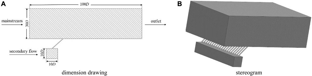
FIGURE 1. Geometry model.
Figure 2 shows the geometric size of the waveform hole, which is the minimum positive period of the cosine function in the spanwise direction (T = 2D). In order to ensure that the opening area of a single waveform hole is equal to that of a standard cylindrical hole, the width of the waveform hole along the flow direction is specified to be 0.4D. In order to facilitate the research, the corresponding phase angle of the trigonometric function at the edge is defined as the initial phase φ, the maximum distance from the equilibrium position in the spanwise direction is the amplitude A, the farthest point away from the equilibrium position along the flow direction is the peak, and the other extreme point is the trough.
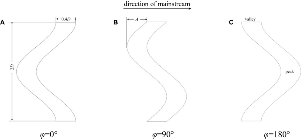
FIGURE 2. Geometric dimensions of waveform hole.
2.2 Parameter definition
Blowing ratio:
In the formula: ρc is the secondary flow density, kg/m3; ρg is the mainstream density, kg/m3; uc is the secondary flow velocity, m/s; ug is the mainstream speed, m/s.
Temperature ratio:
In the formula: Tc is the secondary flow temperature, K; while Tg is the mainstream temperature, K.
Adiabatic cooling efficiency:
In the formula: Tc is the secondary flow temperature, K; Tg is the mainstream temperature, K; Taw is adiabatic wall temperature, K.
Average spanwise cooling efficiency:
In the formula, ηi is the cooling efficiency of the spanwise ith grid, and n is the number of spanwise grids.
2.3 Mesh subdivision
The computational domain uses the commercial software ICEM CFD 2020 to divide the structured grid and set the boundary layer and periodic surface, while ensuring that the y + < 3 near the wall, and the grid near the intersection of the secondary flow. In addition, through the verification of grid independence, the numerical calculation is carried out for different numbers of grids under the same working conditions, and the number of grids is finally determined to be 1.2 million. At this time, the calculation error with the number of grids of 2.4 million and 4.8 million is within 3%, indicating that the number of grids used has high accuracy, as shown in Figure 3, where X is the distance between the measurement position and the center of the waveform hole.
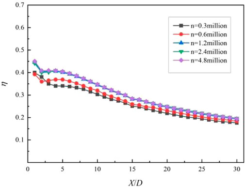
FIGURE 3. Comparison of film cooling efficiency with different mesh numbers.
2.4 Mesh subdivision
The mathematical model of steady-state flow and heat transfer between solid structures and hot or cold fluids is as follows:
Continuity equation:
Momentum equation:
Energy equation:
In the formula, ρ is density, U is speed, p is pressure, τ is shear stress, kf is the thermal conductivity of the fluid, and T is temperature.
2.5 Boundary conditions
The selection of turbulence model is an important factor affecting the numerical results. For the flow separation and heat transfer details, the boundary layer needs to be solved with high precision. To ensure the accuracy of the solution, the SST k-ω turbulence model is selected in this paper. Both the main inlet and the secondary inlet are velocity inlets, and the outlet is pressure outlet. Specific parameters are shown in Table 1. The fluid domain material is incompressible ideal gas, the turbulence degree is 3%, and the others are adiabatic boundaries without heat exchange with the outside world. The coupled algorithm is used to solve the coupling of pressure and velocity, and convergence is based on the residual value less than 10−6.
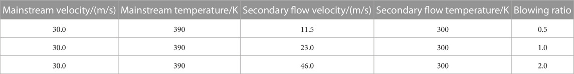
TABLE 1. Boundary conditions.
3 Calculation results and analysis
3.1 Feasibility analysis of calculation
In order to verify the feasibility of the calculation method, the numerical calculation is carried out according to Yhenc’s experiment, and the experimental data are compared with the numerical simulation data in the research of Yuen and Martinez-Botas (2003). Figure 4 shows the comparison of the spanwise average cooling efficiency at the downstream of the standard cylindrical hole when the blowing ratio M = 1 and the incident angle of the cooling air flow is 30°. The error between the experimental data and the simulation results is within 5%, indicating that the adopted calculation method is feasible.
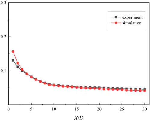
FIGURE 4. Comparison between experimental data and numerical simulation data.
3.2 Comparison of cooling efficiency of different types of film holes
Figure 5 shows that when the blowing ratio M = 1, the temperature ratio K = 1.3 and the opening angle θ = 45°, the shape of the film hole is the velocity vector and temperature distribution of the cylindrical hole, the rectangular hole and the waveform hole at the downstream X/D = 5, respectively. The diameter of the cylindrical hole is D, the length of the rectangular hole is 2D, the width is 0.4D, the initial phase of the waveform hole is 180°, the amplitude is 0.2D, and the width is 0.4D. It can be seen from the figure that kidney-shaped vortices are formed downstream of the film hole center. At this position, the kidney-shaped vortex downstream of the cylindrical hole is the largest, the spanwise cooling airflow coverage is the smallest, the kidney-shaped vortex downstream of the waveform hole is the smallest, the spanwise cooling airflow coverage is the largest, and the downstream of the rectangular hole is between the two.
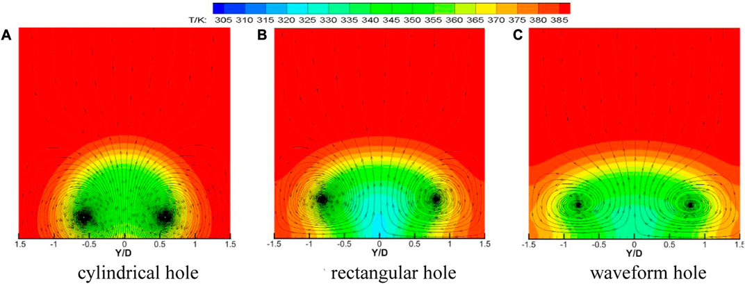
FIGURE 5. Velocity vector and temperature distribution of film holes with three shapes at X/D = 5.
Figure 6 shows the comparison of film cooling efficiency of three different shapes of film holes at different positions along the flow direction when the blowing ratio M = 1, the temperature ratio K = 1.3 and the opening angle θ = 45°. It can be seen from the diagram that the cooling effect of the film hole with cylindrical hole structure in the spanwise direction is poor, and the cooling air fails to diffuse effectively in the spanwise direction under the suppression of the mainstream, and the adhesion effect is poor. Compared with the rectangular hole, the waveform hole structure weakens the energy of the kidney vortex, and the cooling airflow diffuses more evenly in the spanwise direction, and the cooling effect is more significant.
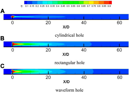
FIGURE 6. Comparison of cooling efficiency of three shapes of film holes along the flow direction.
As shown in Figure 7, when the blowing ratio M = 1, the temperature ratio K = 1.3, and the opening angle θ = 45°, the shape of the film hole is the comparison of the spanwise average cooling efficiency of the cylindrical hole, the rectangular hole and the waveform hole at different downstream positions. It can be seen from the figure that compared with the cylindrical hole, the spanwise average cooling efficiency of the rectangular hole and the waveform hole at the same measurement position is greatly improved. The spanwise average film cooling efficiency of the rectangular hole structure is increased by about 100%, and the spanwise average film cooling efficiency of the waveform hole structure is increased by about 130%. Compared with the rectangular hole, the waveform hole structure has a better spanwise cooling effect downstream of the film hole, especially when 5 < X/D < 15, the cooling effect of the waveform hole structure is more significant.
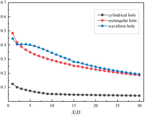
FIGURE 7. Comparison of cooling efficiency of three shapes of film holes.
3.3 The influence of the initial phase of the waveform hole on the cooling efficiency
Figure 8 shows the velocity vector and temperature distribution of waveform holes with different initial phases at downstream X/D = 5 when blowing ratio M = 1, temperature ratio K = 1.3, opening angle θ = 45°, and amplitude A = 0.2D. It can be seen from the figure that a kidney-shaped vortex is formed downstream of the film hole outlet. When the initial phase ϕ = 0°, the trough is at the center of the film hole, the kidney vortex generated at the convergence of the secondary flow and the mainstream reaches the maximum, and the coverage of the cooling air flow in the spanwise direction is the smallest. When the initial phase ϕ = 90°, the peak and trough are at Y/D = ±0.5. It can be seen that the vortex at the downstream of the trough is significantly larger than that at the downstream of the peak. The cooling effect of the cooling air flow at Y/D > 0 is better than that at Y/D < 0. When the initial phase ϕ = 180°, the kidney vortex generated at the convergence of the secondary flow and the mainstream is the smallest, and the coverage of the cooling air flow in the spanwise direction reaches the maximum.
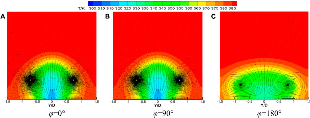
FIGURE 8. Velocity vector and temperature distribution at X/D = 5 for waveform holes with different initial phases.
Figure 9 shows the comparison of film cooling efficiency at different positions along the flow direction of the wavy holes with different initial phases when the blowing ratio M = 1, the temperature ratio K = 1.3, the opening angle θ = 45°, and the amplitude A = 0.2D. It can be seen from the figure that when the initial phase ϕ = 0°, the cooling air flow is unevenly distributed in the spanwise direction, and the cooling effect is the worst. When the initial phase ϕ = 90°, due to the peaks and troughs on both sides of the center of the film hole, the spanwise pressure difference is uneven, which makes the secondary flow spread faster to the downstream side of the trough. When the initial phase ϕ = 180°, the distribution of the cooling airflow in the spanwise direction is more uniform, and the cooling effect is the best.
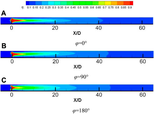
FIGURE 9. Comparison of cooling efficiency along the flow direction of waveform holes with different initial phases.
Figure 10 shows that when the blowing ratio M = 1, the temperature ratio K = 1.3, the opening angle θ = 45°, and the amplitude A = 0.2D, the mass flow rate at the outlet of the waveform hole with different initial phases is compared. It can be seen from the figure that with the increase of the initial phase ϕ, the flow rate of the cooling gas flowing from the trough gradually decreases, and the flow rate of the cooling gas flowing from the peak gradually increases. This is mainly due to the friction and viscosity between the wall surface of the film hole and the cooling gas, resulting in a slow flow rate of the fluid near the hole wall.
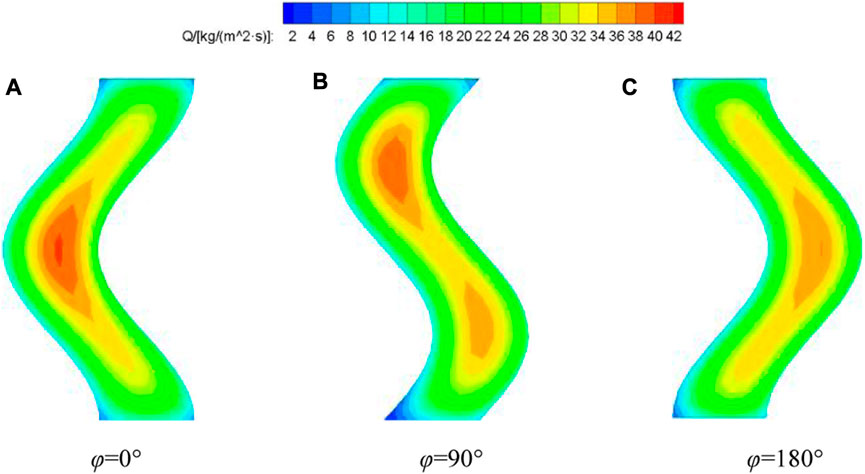
FIGURE 10. Comparison of mass flow at the outlet of waveform holes with different initial phases.
Figure 11 shows the comparison of the spanwise average cooling efficiency of the waveform holes with different initial phases at different downstream positions when the blowing ratio M = 1, the temperature ratio K = 1.3, the opening angle θ = 45°, and the amplitude A = 0.2D. When 0 < X/D < 3 near the wall, the cooling efficiency of the cooling air flow on the hot side wall increases with the increase of the initial phase. This is mainly because the trough is farther away from the same measuring point on the hot side wall surface than other positions on the waveform hole, so the cooling gas flowing from the trough has more sufficient time and distance to be fully adhered to the wall after being suppressed by the mainstream. Due to the existence of viscosity, the average flow rate of the secondary flow flowing from the central area of the film hole is larger. Therefore, when the trough is at the most central position of the waveform hole (ϕ = 0°), the mainstream can suppress more flow of cooling gas in the area of 0 < X/D < 3 downstream of the film hole outlet, and the cooling efficiency in this area will be higher. Similarly, when the trough is at the most marginal position of the waveform hole (ϕ = 180°), the average flow rate of cooling gas from the trough is the smallest, and the cooling efficiency is the lowest in the region of 0 < X/D < 3 downstream of the film hole outlet. When near the wall X/D > 3, the cooling efficiency of the cooling air flow on the hot side wall decreases with the increase of the initial phase. This is mainly because the cooling gas flowing from the trough is first suppressed by the mainstream to the near wall and diffuses in the spanwise direction. Therefore, when the trough is at the most central position of the waveform hole (ϕ = 0°), the cooling gas dissipates too much at the near wall 0 < X/D < 3, resulting in lower cooling efficiency at the near wall X/D > 3. In the same way, when the trough is at the most edge position of the waveform hole (ϕ = 180°), the cooling gas dissipates the least at the near wall 0 < X/D < 3, resulting in the highest cooling efficiency at the near wall X/D > 3.
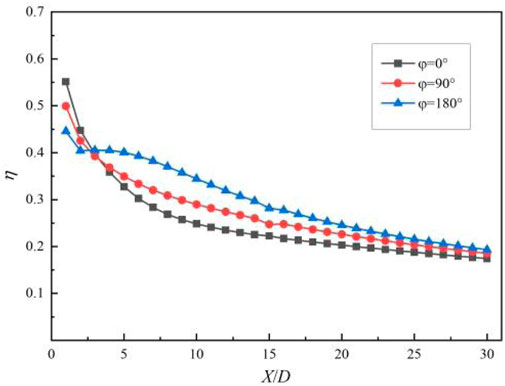
FIGURE 11. Comparison of cooling efficiency of waveform holes with different initial phases.
Figure 12 shows the comparison of the spanwise average cooling efficiency of the waveform holes with different initial phases at different downstream positions when the temperature ratio K = 1.3, the opening angle θ = 45°, the amplitude A = 0.2D, and the blowing ratio M is 0.5, 1, and 2, respectively. It can be seen from the figure that when the blowing ratio M = 0.5, the change of the initial phase of the waveform hole has little effect on the spanwise average cooling efficiency of each measured position on the downstream wall of the film hole outlet, but the overall cooling efficiency increases with the increase of the initial phase ϕ. When the blowing ratio M ≥ 1, the initial phase ϕ of the waveform hole has a great influence on the spanwise average cooling efficiency of the downstream wall of the film hole outlet, and the difference is more obvious when the blowing ratio M = 2.
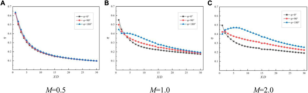
FIGURE 12. Comparison of cooling efficiency of waveform holes at different initial phases under different blowing ratios.
3.4 The influence of the amplitude of the waveform hole on the cooling efficiency
Figure 13 shows the velocity vector and temperature distribution of the waveform holes with different amplitudes at the downstream X/D = 5 when the blowing ratio M = 1, the temperature ratio K = 1.3, the opening angle θ = 45°, and the initial phase ϕ = 180°. It can be seen from the figure that the kidney-shaped vortex formed downstream of the center of the waveform hole gradually flattened with the increase of amplitude A, which effectively inhibited the mixing of mainstream gas and cooling gas. In addition, when the amplitude A is 0.6D, two symmetrical vortices are formed on both sides of the kidney-shaped vortex, which weakens the area of the kidney-shaped vortex. In the temperature distribution, when the amplitude A increases from 0.1D to 0.4D, the distribution of the cooling airflow in the spanwise direction gradually tends to be uniform, and the full coverage of the cooling airflow is achieved when A = 0.4D. When the amplitude A increases from 0.4D to 0.6D, although the cooling air flow is fully covered in the spanwise direction, when the amplitude A = 0.6D, two symmetrical vortices at Y/D = ±1.25D aggravate the mixing of the mainstream and the secondary flow, which makes the cooling effect near the wall worse.
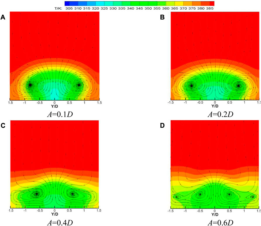
FIGURE 13. Comparison of cooling efficiency of waveform holes at different initial phases under different blowing ratios.
Figure 14 shows the comparison of film cooling efficiency at different positions along the flow direction of the wavy holes with different amplitudes when the blowing ratio M = 1, the temperature ratio K = 1.3, the opening angle θ = 45°, and the initial phase ϕ = 180°. It can be seen from the figure that when 0 < X/D < 5, the smaller the amplitude A, the better the cooling effect of the cooling air flow on the hot side wall. When X/D > 5, as the amplitude A increases, the cooling air flow cools the hot side wall more evenly. However, when the amplitude A increases from 0.4D to 0.6D, although the cooling air flow cools the hot side wall more evenly, at the same measurement position, the spanwise film cooling efficiency is the highest when the amplitude A = 0.4D.
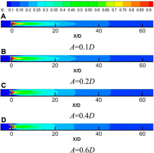
FIGURE 14. Comparison of cooling efficiency of waveform holes with different amplitudes along the flow direction.
Figure 15 shows the comparison of the spanwise average cooling efficiency of the waveform holes with different amplitudes at different downstream positions when the blowing ratio M = 1, the temperature ratio K = 1.3, the opening angle θ = 45°, and the initial phase ϕ = 180°. It can be seen from the diagram that when the amplitude A increases from 0.1D to 0.4D, the cooling efficiency of the secondary flow to the wall surface gradually increases. This is mainly because as the amplitude A increases, the relative distance between the peak and trough of the waveform hole also increases. Therefore, the velocity difference of the cooling gas flowing from the peak and trough to the same position near the wall surface gradually increases, so the diffusion speed of the cooling gas flowing from the peak in the spanwise direction also increases, which can cool the hot side wall faster and more evenly. When the amplitude A increases from 0.4D to 0.6D, the cooling efficiency of the secondary flow on the wall surface gradually decreases. Although the increase of the amplitude A will accelerate the diffusion of the cooling air flow in the spanwise direction, it also widens the distance between the trough and the hot side wall surface, so that the cooling air flow from the vicinity of the trough has lost too much when it reaches each measurement position, and the acceleration of the cooling air diffusion speed in the spanwise direction cannot compensate for this loss. In the scope of this study, when the amplitude A = 0.4D, the waveform hole structure has the best cooling effect on the hot side wall.
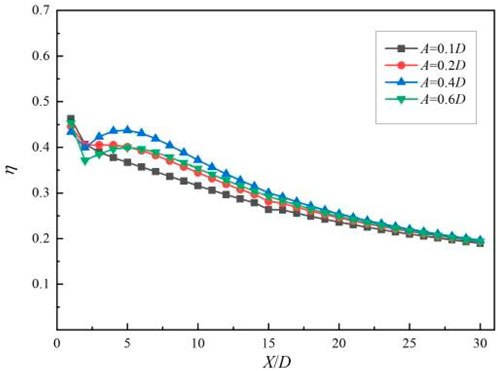
FIGURE 15. Comparison of cooling efficiency of waveform holes with different amplitudes.
4 Conclusion
Through the numerical simulation results and analysis of the flow and heat transfer under the waveform holes with different geometric structures, the following conclusions can be drawn within the scope of this study:
1. At the same blowing ratio M = 1, compared with the cylindrical hole, the average spanwise cooling efficiency of the rectangular hole and the waveform hole at the same measurement position is greatly improved. The average spanwise film cooling efficiency of the rectangular hole structure is increased by about 100%, and the average spanwise film cooling efficiency of the waveform hole structure is about 130%.
2. At the same blowing ratio M = 1, due to the fluctuation of the waveform hole in the spanwise direction, the cooling gas flowing from the trough is first suppressed by the mainstream, and because of the friction and viscosity between the wall surface of the film hole and the cooling gas, the cooling efficiency decreases with the increase of the initial phase ϕ in the region of 0 < X/D < 3 near the wall surface downstream of the film hole. In the region of X/D > 3, the cooling efficiency increases with the increase of the initial phase ϕ.
3. At a small blowing ratio, the geometric structure of the waveform hole has little effect on the cooling effect of the wall. When the geometric structure of the waveform hole is changed, the wall cooling effect will change greatly at a large blowing ratio.
4. At the same blowing ratio M = 1, with the increase of the amplitude A, the relative distance between the peak and the trough also increases, and the velocity difference at the same measurement position downstream of the film hole will also increase, and the diffusion speed of the cooling gas in the spanwise direction will be accelerated. However, when the amplitude A increases from 0.4D to 0.6D, the cooling gas flowing from the trough dissipates too much, and the acceleration of the cooling gas diffusion rate cannot compensate for this loss. The spanwise average cooling efficiency of the cooling gas near the wall reaches the maximum at A = 0.4D.
Data availability statement
The original contributions presented in the study are included in the article/supplementary material, further inquiries can be directed to the corresponding author.
Author contributions
CQ contributed to conception and design of the study, the database and the statistical analysis. MW wrote the first draft of the manuscript. WY wrote sections of the manuscript. YL helped typeset the manuscript, and BZ provided the topic selection ideas. All authors contributed to the article and approved the submitted version.
Conflict of interest
The authors declare that the research was conducted in the absence of any commercial or financial relationships that could be construed as a potential conflict of interest.
Publisher’s note
All claims expressed in this article are solely those of the authors and do not necessarily represent those of their affiliated organizations, or those of the publisher, the editors and the reviewers. Any product that may be evaluated in this article, or claim that may be made by its manufacturer, is not guaranteed or endorsed by the publisher.
References
Baheri, S., Tabrizi, S. A., and Jubran, B. (2008). Film cooling effectiveness from trenched shaped and compound holes. Heat mass Transf. 44, 989–998. doi:10.1007/s00231-007-0341-9
Baldauf, S. A., Scheurlen, M., Schulz, A., and Wittig, S. (2002). Correlation of film cooling effectiveness from thermographic measurements at engine like conditions. Turbo Expo Power Land, Sea, Air 36088, 149–162. doi:10.1115/1.1504443
Bunker, R. (2011). A study of mesh-fed slot film cooling. J. Turbomach. 133, 011022. doi:10.1115/1.4000548
Bunker, R. S. (2017). “Evolution of turbine cooling,” in Turbo expo: Power for land, sea, and air (American Society of Mechanical Engineers), 50770, V001T51A001.
Colban, W. F., Thole, K. A., and Bogard, D. (2008). A film-cooling correlation for shaped holes on a flat-plate surface. Turbo Expo Power Land, Sea, Air 43147, 65–79. doi:10.1115/1.4002064
Gorelov, Y. G., and Tyul’kov, K. (2018). The 3d computational investigation of film cooling effectiveness for turbine nozzle vanes with “meridian constriction” and shaped film-cooling holes. Russ. Aeronaut. 61, 49–55. doi:10.3103/s1068799818010087
Gritsch, M., Schulz, A., and Wittig, S. (2000). Film-cooling holes with expanded exits: near-hole heat transfer coefficients. Int. J. Heat Fluid Flow 21, 146–155. doi:10.1016/s0142-727x(99)00076-4
Han, J.-C., Dutta, S., and Ekkad, S. (2012). Gas turbine heat transfer and cooling technology. CRC Press.
Kusterer, K., Tekin, N., Bohn, D., Sugimoto, T., Tanaka, R., and Kazari, M. (2012). “Experimental and numerical investigations of the nekomimi film cooling technology,” in Turbo expo: Power for land, sea, and air (American Society of Mechanical Engineers), 44700, 1299–1310.
Kusterer, K., Tekin, N., Reiners, F., Bohn, D., Sugimoto, T., Tanaka, R., et al. (2013). “Highest-efficient film cooling by improved nekomimi film cooling holes: part 1—ambient air flow conditions,” in Turbo expo: Power for land, sea, and air (American Society of Mechanical Engineers), 55157, V03BT-13A040.
Miller, K. L., and Crawford, M. E. (1984). “Numerical simulation of single, double, and multiple row film cooling effectiveness and heat transfer,” in Turbo expo: Power for land, sea, and air (American Society of Mechanical Engineers), 79498, V004T09A008.
Okita, Y., and Nishiura, M. (2007). Film effectiveness performance of an arrowhead-shaped film-cooling hole geometry. J. Turbomach. 129, 331–339. doi:10.1115/1.2437781
Schmidt, D. L., Sen, B., and Bogard, D. G. (1996). Film cooling with compound angle holes: adiabatic effectiveness. J. Turbomach. 118, 807–813. doi:10.1115/1.2840938
Walters, D. K., and Leylek, J. H. (2000). A detailed analysis of film-cooling physics: part i—streamwise injection with cylindrical holes. J. Turbomach. 122, 102–112. doi:10.1115/1.555433
Yang, X., Liu, Z., and Feng, Z. (2015). Numerical evaluation of novel shaped holes for enhancing film cooling performance. J. Heat Transf. 137, 071701. doi:10.1115/1.4029817
Yuen, C., and Martinez-Botas, R. (2003). Film cooling characteristics of a single round hole at various streamwise angles in a crossflow: part i effectiveness. Int. J. Heat Mass Transf. 46, 221–235. doi:10.1016/s0017-9310(02)00274-0
Keywords: waveform hole, amplitude, initial phase, film cooling efficiency, blowing ratio
Citation: Qian C, Wang M, Yang W, Liu Y and Zhang B (2023) Study on the effect of waveform film holes on film cooling efficiency. Front. Energy Res. 11:1249759. doi: 10.3389/fenrg.2023.1249759
Received: 04 July 2023; Accepted: 06 September 2023;
Published: 04 October 2023.
Edited by:
Yakubu Ibrahim Seini, University for Development Studies, GhanaCopyright © 2023 Qian, Wang, Yang, Liu and Zhang. This is an open-access article distributed under the terms of the Creative Commons Attribution License (CC BY). The use, distribution or reproduction in other forums is permitted, provided the original author(s) and the copyright owner(s) are credited and that the original publication in this journal is cited, in accordance with accepted academic practice. No use, distribution or reproduction is permitted which does not comply with these terms.
*Correspondence: Weihua Yang, yangwh@nuaa.edu.cn